Table of Contents
Advertisement
Quick Links
Advertisement
Table of Contents

Related Manuals for Air Lift Liad CONTROLLER I 25655


Summary of Contents for Air Lift Liad CONTROLLER I 25655
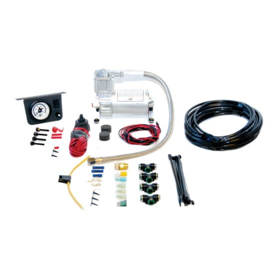
- Page 1 Kit 25655 ™ Single Gauge Controller Cover image may not depict actual kit. InstallatIon GuIde For maximum effectiveness and safety, please read these instructions completely before proceeding with installation. Failure to read these instructions can result in an incorrect installation.
-
Page 3: Table Of Contents
taBle oF Contents Introduction . . . . . . . . . . . . . . . . . . . . . . . . . . . . . . . . . . . 2 Important Safety Notice . -
Page 4: Introduction
Air Lift Company reserves the right to make changes and improvements to its products and publications at any time. For the latest version of this manual, contact Air Lift Company at (800) 248-0892 or visit our website at www.airliftcompany.com. -
Page 5: Installation Diagram
(Already (Already installed) installed) Fuse Adapter #3 Bellows * Uses 3/16 (smaller) Female Push On Connector (Already installed) Inset A fig. 1 Missing or damaged parts? Call Air Lift customer STOP! service at (800) 248-0892 for a replacement part. MN-342... -
Page 6: Installing The Loadcontroller I System
LoadController I Installing the loadController I system RECOMMENDED COMPRESSOR LOCATIONS Important LOCATE COMPRESSOR IN DRY, PROTECTED AREA ON VEHICLE. DIRECT SPLASH OR ExCESSIVE MOISTURE CAN DAMAGE THE COMPRESSOR AND CAUSE SYSTEM FAILURE. Disclaimer: If you choose to mount the compressor outside the vehicle please keep in mind the compressor body must be shielded from direct splash and the intake should be snorkeled inside the vehicle. -
Page 7: Mounting The Dash Panel
LoadController I fig. 3 6. Install the fitting into the pressure port side of the leader hose (Figure 4). Push-To- Connect Fitting Hose fig. 4 MOuNTING ThE DASh PANEL 1. Select a convenient, sturdy mounting location for the gauge panel. 2. -
Page 8: Installing The Air Line
LoadController I your thumb against the front side of the switch, push the connector onto the remaining terminal on the back of the ON/OFF switch on the gauge panel. 6. Route the white wire for the illuminated gauge to an accessory power source. Attach the black wire to an adequate ground. -
Page 9: Inflation Control
LoadController I INFLATION CONTROL 1. Your vehicle is equipped with rear air springs. The following procedure is a ìguideî to assist you in leveling your vehicle to provide the best possible ride and handling. 2. Fill the air springs to maximum recommended pressure. The pressure can be increased from the dash control or the inflation valves located just ahead of the rear wheels. -
Page 10: Warranty And Returns Policy
Air Lift 1000 ....Lifetime Limited LoadController/Dual ..2 Year Limited RideControl . -
Page 11: Replacement Information
LoadController I Replacement Information If you need replacement parts, contact the local dealer or call Air Lift customer service at (800) 248-0892. Most parts are immediately available and can be shipped the same day. Contact Air Lift Company customer service at (800) 248-0892 first if: •... - Page 12 Thank you for purchasing Air Lift products — the professional installer’s choice! Air Lift Company • 2727 Snow Road • Lansing, MI 48917 or PO Box 80167 • Lansing, MI 48908-0167 Toll Free (800) 248-0892 • Local (517) 322-2144 • Fax (517) 322-0240 • www.airliftcompany.com...
Need help?
Do you have a question about the Liad CONTROLLER I 25655 and is the answer not in the manual?
Questions and answers