
Subscribe to Our Youtube Channel
Related Manuals for Fass FA F15 220G


Summary of Contents for Fass FA F15 220G
- Page 1 INSTALLATION MANUAL APPLICATION: FA F15 220G (220GPH @ 55psi) Ford Powerstroke 7.3L/6.0L *bypassing the factory Lift Pump* Standard Pickup Truck 1999-2007 Revision Date: 10/12/2015...
- Page 2 Building extremely “High-Quality” fuel products is our business. We concentrate all of our efforts in this arena. No one else is as specialized as FASS in what we do! This is one of the ingre- dients to insure you are running with the “Highest-Quality” fuel system in the world! We have im- plemented very rigorous testing procedures to provide the “Highest Quality”...
- Page 3 Keep debris from entering the internals of the system during installation. Getting debris in the “T” port can lock up the motor. If the motor does lock up from debris call FASS for technical assistance. Be sure to utilize the inline fuel filter included in this kit, or the equivalent, to prevent a ...
- Page 4 4. For best results in accuracy and efficiency (due to training, communication, and our relationship with our dealer network), we recommend a ViP FASS dealer for the in- stallation. They are prepared to install the FASS fuel pumps with the most efficien- cy.
-
Page 5: Installation
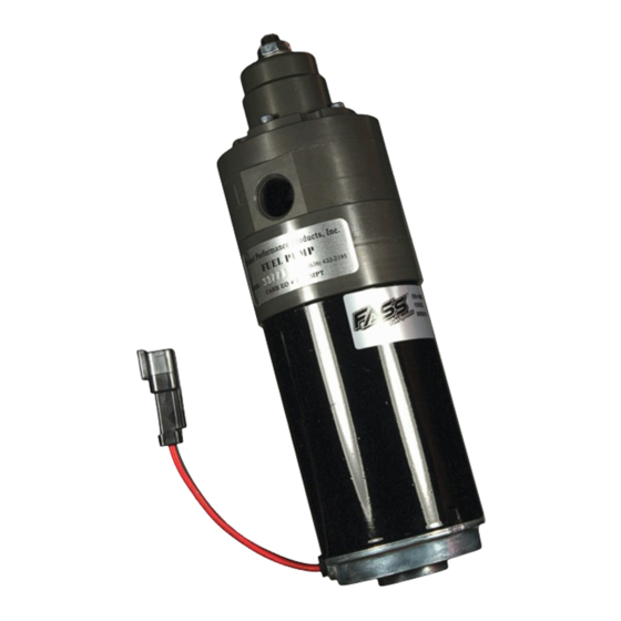
Adjustable Fuel Pump Series 220 GPH 55 PSI (Approximately) A fuel pressure gauge is highly recommended to identify fuel filter life and to prevent engine damage! Adjustment Lock Nut Set screw Boost Compensation Port ‘T’ Fuel Inlet Port “E” To Engine Fuel Pressure Port Installation Step 1:... - Page 6 Contents THB-1001 BHB-1001 FF-3248 MP-9049 FPB-2005 PFB-2001C WH-1005 FL-1002 x14’...
- Page 7 Mounting Package Contents *WE-1001* RS-1002 BHF-1002 PLB-12516 10-300 *Cable Ties* PL-1005 Butt Splice Ring Terminal 1/2” Plug PLB-1238 PL-1004 HC-1001 OR-223 ST-1005Px16” BHN-1001 LW-1001 1/2” Washers 1 Hex Bolt 1/2” -20 x 1 1/2” 1/4” Nut 1/4” washer RS-2001 1/4 - 20x1.5” 1/4 - 20x1.75”...
- Page 8 The installation of the electrical harness is done first, allowing power to be applied to the pump for lubrication purposes later in the installation. Disconnect battery before beginning installation. Using ring terminals, attach red wire of the WH-1005 to the positive battery terminal. The use of corrosion preventative spray is recommended.
- Page 9 Some of the photo’s are of a different application, procedures are the same. NOTE: Before installing fittings make sure to inspect for burs or flare imperfections. When cutting fuel line make sure to blow out line to keep debris from moving forward. Very Important: Before removing the fuel tank, identify “ALL”...
-
Page 10: Very Important
Before drilling marked location, clean area of debris. Using the photo double check area selected for any interference including the fuel level arm. Drill a 1 3/8” hole, catching all debris. De-bur hole and remove any missed debris in the fuel tank. VERY IMPORTANT: Support fuel tank on both ends allowing the natural formation of the tank to take place. - Page 11 Some of the photo’s are of a different application, procedures are the same. Insert PFB-2001C in to bed channel align the nut with the opening on the channel. Secure PFB-2002 and RS-2001 with (1) hex bolt 1/2” -20 x 1 1/2” and (1) 1/2” washer to FPB-2005 Secure THB-1001 to bolt on bracket with the RS-1002 and the (5)-1/4-20x1 bolts, 1/4 washers, and 1/4 nuts.
- Page 12 FASS pump. Reconnect the battery. Turn key to the “On” position. With the FASS pump on, squirt a liberal amount of WD-40 or other lubricant into the “T” port. This procedure will “wet” the Gerotor and allow for better suction during Note: Do Not Put Thread Tape on Flare of Fitting initial priming.
- Page 13 Butt Splice to the factory power lead and the WE-1001. Shrink blue cover with an appropriate heat source. Route FASS wire harness/wire extension along the frame rail to factory lift pump. Remove the power plug from the factory lift pump.
- Page 14 The factory return line on the 7.3L does not require any modification. Route the fuel line from the “E” port of the FASS to the engines fuel feed line quick disconnect and cut to length. Insert the PLB-12516 into FASS fuel line using oil.
- Page 15 Route the fuel line from the “E” port of the FASS to the engines fuel feed line quick disconnect and cut to length. Insert the PLB-1238 into FASS fuel line using oil. Slide the PLB-1238 into the factory quick disconnect until you hear a click.
- Page 16 Electrical harness and fuel lines secured and properly tightened? Reconnect the battery. Has the system been primed? 1. Turn key to the ignition position, turning on the FASS pump for 15 sec.. 2. Crank engine and allow to run for at least 1 minute. Check for leaks. ...
- Page 17 Disclaimer: To help insure you receive the proper system and customer support at the local level, FASS has a VIP and Authorized Dealer network representing FASS products. This is one reason you must purchase through a dealer to comply with our warranty policies.
Need help?
Do you have a question about the FA F15 220G and is the answer not in the manual?
Questions and answers