Table of Contents
Advertisement
Quick Links
INTRODUCTION
Information contained herein is current at date of publication. As a result of improvements,
some numerical values and illustrations contained in this publication may not correspond to the
factual specification of the machine supplied to the user. The manufacturer reserves the right to
introduce design changes in machines produced that facilitate operation and improve the quality
of their work, without making minor amendments to this Operator's Manual.
This Operator's Manual is an integral part of the machine's documentation. Before using the
machine, the user must carefully read
recommendations. This guarantees safe operation and ensures failure-free work of the
machine. The machine is designed to meet obligatory standards, documents and legal
regulations currently in force.
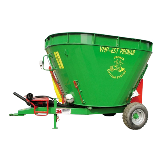
The manual describes the basic safety rules and operation of the Pronar VMP-5ST and Pronar
VMP-6ST mixer-feeders.
If the information contained in the Operator's Manual needs clarification then the user should
refer for assistance to the sale point where the machine was purchased or to the Manufacturer.
MANUFACTURER'S ADDRESS:
CONTACT TELEPHONES
PRONAR Sp. z o.o.
ul. Mickiewicza 101A
17-210 Narew
+48 085 681 63 29
+48 085 681 63 81
this Operator's Manual and observe
+48 085 681 64 29
+48 085 681 63 82
all
Advertisement
Table of Contents

Related Manuals for PRONAR VMP-5ST


Summary of Contents for PRONAR VMP-5ST
- Page 1 The machine is designed to meet obligatory standards, documents and legal regulations currently in force. The manual describes the basic safety rules and operation of the Pronar VMP-5ST and Pronar VMP-6ST mixer-feeders. If the information contained in the Operator's Manual needs clarification then the user should refer for assistance to the sale point where the machine was purchased or to the Manufacturer.
- Page 2 SYMBOLS APPEARING IN THIS OPERATOR'S MANUAL Information, descriptions of danger and precautions and also recommendations and prohibitions associated with user safety instructions are marked: and also preceded by the word "DANGER”. Failure to observe the instructions may endanger the machine operator's or other person's health or life. Particularly important information and instructions, the observance of which is essential, are distinguished in the text by the sign: and also preceded by the word "ATTENTION".
- Page 3 DIRECTIONS USED IN THIS OPERATOR'S MANUAL Left side – side to the left hand of the operator facing in the direction of machine's forward travel. Right side – side to the right hand of the operator facing in the direction of machine's forward travel.
-
Page 5: Table Of Contents
TABLE OF CONTENTS 1 BASIC INFORMATION IDENTIFICATION 1.1.1 IDENTIFICATION OF MIXER FEEDER 1.1.2 AXLE IDENTIFICATION 1.1.3 LIST OF SERIAL NUMBERS PROPER USE EQUIPMENT WARRANTY TERMS TRANSPORT 1.5.1 TRANSPORT ON VEHICLE 1.10 1.5.2 INDEPENDENT TRANSPORT BY THE USER 1.11 ENVIRONMENTAL HAZARDS 1.11 WITHDRAWAL FROM USE 1.12... - Page 6 3 DESIGN AND OPERATION TECHNICAL SPECIFICATION DESIGN OF MIXER FEEDER 3.2.1 CHASSIS 3.2.2 TANK 3.2.3 DRIVE TRANSMISSION 3.2.4 HYDRAULIC SYSTEM OF THE SLIDE GATES 3.2.5 TRANSMISSION LUBRICATION SYSTEM 3.2.6 WEIGHING SYSTEM 3.10 4 CORRECT USE PREPARING THE MIXER FEEDER FOR NORMAL USE 4.1.1 PRELIMINARY INFORMATION 4.1.2 HAND-OVER AND INSPECTION OF THE MACHINE AFTER DELIVERY...
- Page 7 5.2.2 CHECKING WHEEL AXLE BEARINGS FOR SLACKNESS 5.2.3 ADJUSTMENT OF AXLE BEARING SLACKNESS 5.2.4 MOUNTING AND DISMOUNTING WHEEL, INSPECTION OF WHEEL NUT TIGHTENING 5.2.5 CHECKING AIR PRESSURE IN TYRES, EVALUATING TECHNICAL CONDITION OF TYRES AND STEEL WHEELS HYDRAULIC SYSTEM MAINTENANCE 5.3.1 PRELIMINARY INFORMATION 5.3.2 CHECKING HYDRAULIC SYSTEM TIGHTNESS 5.10...
-
Page 9: Basic Information
SECTION BASIC INFORMATION... -
Page 10: Identification
Pronar VMP-5ST | Pronar VMP6-ST SECTION 1 1.1 IDENTIFICATION 1.1.1 IDENTIFICATION OF MIXER FEEDER FIGURE 1.1 Location of the data plate and serial number (1) data plate, (2) example of serial number... -
Page 11: Axle Identification
SECTION 1 Pronar VMP-5ST | Pronar VMP6-ST Pronar VMP-5ST and VMP-6ST mixer feeders are marked with the data plate (1) and the serial number (2) located on a gold painted rectangle. The serial number and the data plate are located on the right longitudinal member of the frame - figure (1.1). When buying the machine check that the serial numbers on the machine agree with the number written in the WARRANTY BOOKand in the sales documents. -
Page 12: List Of Serial Numbers
Pronar VMP-5ST | Pronar VMP6-ST SECTION 1 FIGURE 1.2 Location of the axle data plate (1) data plate, (2) wheel axle, 1.1.3 LIST OF SERIAL NUMBERS In the event of ordering a replacement part or in the case of the appearance of problems... -
Page 13: Proper Use
AXLE SERIAL NUMBER 1.2 PROPER USE VMP-5ST and VMP-6ST mixer feeders are designed specially for modern cattle breeding farms. The machines are designed for preparing feed in the animal feeding systems of TMR type (Total Mixed Ration), PMR type (Partially Mixed Ration) or similar systems. Feed ingredients are batched to the mixer feeder tank where they are disintegrated and thoroughly mixed. - Page 14 Pronar VMP-5ST | Pronar VMP6-ST SECTION 1 Using it as intended also involves all actions connected with the safe and proper operation and maintenance of the machine. Due to the above, the user is obliged to: • carefully read the OPERATOR'S MANUAL of the mixer feeder, WARRANTY...
-
Page 15: Equipment
SECTION 1 Pronar VMP-5ST | Pronar VMP6-ST CONTENTS UNIT REQUIREMENTS Tractor hitches Minimum lifting capacity of the hitching system VMP-5ST VMP-6ST Other requirements Minimum tractor power demand VMP-5ST kW / hp 40.4 / 55 VMP-6ST kW / hp 44.1 / 60... -
Page 16: Warranty Terms
Information on tyres is provided at the end of this publication in ANNEX A. 1.4 WARRANTY TERMS PRONAR Sp. z o.o., Narew guarantees the reliable operation of the machine when it is used according to its intended purpose as described in the OPERATOR'S MANUAL. The repair period is specified in the WARRANTY BOOK. -
Page 17: Transport
SECTION 1 Pronar VMP-5ST | Pronar VMP6-ST • bearings, • cutting blades. The warranty service only applies to such cases as: mechanical damage which is not the user's fault, factory defects of parts, etc. In the event of damage arising from: •... -
Page 18: Transport On Vehicle
Pronar VMP-5ST | Pronar VMP6-ST SECTION 1 1.5.1 TRANSPORT ON VEHICLE Loading and unloading of mixer feeder from vehicle shall be conducted using loading ramp with the aid of agricultural tractor, overhead crane or hoisting crane. During work, adhere to the general principles of occupational health and safety (OHS) applicable to reloading work. -
Page 19: Independent Transport By The User
SECTION 1 Pronar VMP-5ST | Pronar VMP6-ST in order to immobilise the machine. If necessary, cover the sharp edges of the mixer feeder in order to protect the securing straps from breaking during transport. DANGER Incorrect use of securing measures may cause an accident. -
Page 20: Withdrawal From Use
Pronar VMP-5ST | Pronar VMP6-ST SECTION 1 DANGER Used hydraulic or gear oil or gathered remains mixed with absorbent material should be stored in a precisely marked container. Do not use food packaging for this purpose. While carrying out maintenance and repair work, which involves the risk of an oil leak, this work should take place on an oil resistant floor or surface. - Page 21 SECTION 1 Pronar VMP-5ST | Pronar VMP6-ST DANGER During dismantling, use the appropriate tools, equipment (overhead travelling crane, crane or hoist etc.) and use personal protection equipment, i.e. protective clothing, footwear, gloves and eye protection etc. Avoid contact of skin with oil. Do not allow used hydraulic oil to spill.
- Page 22 Pronar VMP-5ST | Pronar VMP6-ST SECTION 1 1.14...
-
Page 23: Safety Advice
SECTION SAFETY ADVICE... -
Page 24: Basic Safety Rules
Pronar VMP-5ST | Pronar VMP-6ST SECTION 2 2.1 BASIC SAFETY RULES 2.1.1 BASIC SAFETY RULES • Before using the mixer feeder, the user must carefully read this Operator's Manual and the Operator's Manual of the PTO shaft. During use all the recommendations laid down in this Operator's Manual should be observed. -
Page 25: Hitching And Unhitching From Tractor
SECTION 2 Pronar VMP-5ST | Pronar VMP-6ST • Before using the machine always check its technical condition, and in particular: technical condition of the drawbar, hydraulic system, safety guards and air pressure in tyres. • The user is obliged to acquaint himself with the principles of safe operation, adjustment methods and inspection points of the mixer feeder and with the risks resulting from operation and maintenance of the machine. -
Page 26: Loading The Mixer Feeder And Feed Mixing
Pronar VMP-5ST | Pronar VMP-6ST SECTION 2 • The machine unhitched from the tractor must be positioned on a level ground, supported by the parking stand and secured against rolling using wheel chocks. Terminals of hydraulic and electrical conduits should be protected against contamination. -
Page 27: Hydraulic System
SECTION 2 Pronar VMP-5ST | Pronar VMP-6ST • Maintain constant auger rotation speed while mixing the feed. • Do not exceed the maximum rotational speed of drive shaft. • During manual loading, do NOT stand on a silo or hay stack located above the mixer feeder tank edge. - Page 28 Pronar VMP-5ST | Pronar VMP-6ST SECTION 2 the safety guards are in good condition and in place. Damaged or incomplete sub-assemblies must be exchanged for original new ones. • After connecting shaft ensure that it is correctly and safely connected to the tractor and to the machine.
-
Page 29: Cleaning, Maintenance And Adjustment
SECTION 2 Pronar VMP-5ST | Pronar VMP-6ST • Disconnect the drive shaft each time when it is not necessary to drive the machine, or when the tractor and mixer feeder are at an unsuitable angle to each other. 2.1.6 CLEANING, MAINTENANCE AND ADJUSTMENT •... - Page 30 Pronar VMP-5ST | Pronar VMP-6ST SECTION 2 • Welding works may be performed only by persons having appropriate authorisations for this type of works. • Before welding or electrical work, the mixer feeder should be disconnected from the power supply, if the machine is connected to the tractor (disconnect the tractor negative battery cable (-), disconnect connection lead).
- Page 31 SECTION 2 Pronar VMP-5ST | Pronar VMP-6ST • Regularly check technical condition and mounting of all guards and protective elements. • Should it be necessary to change individual parts, use only original parts or those indicated by the Manufacturer. Non-adherence to these requirements may put the user and other people's health and life at risk, and also damage the machine.
- Page 32 Pronar VMP-5ST | Pronar VMP-6ST SECTION 2 • Since the cutting blades are very sharp, exercise due caution when mounting, dismounting or adjusting the blades or when being inside the tank. • Remove the remains of feed from the mixer feeder each time after finished work.
-
Page 33: Safe Driving
SECTION 2 Pronar VMP-5ST | Pronar VMP-6ST 2.1.7 SAFE DRIVING FIGURE 2.1 Method of placing chocks (1) chock, (2) chock bracket • Driving on public roads is forbidden. The mixer feeder may be used only at the farm and possibly on non-public access roads. -
Page 34: Tyres
Pronar VMP-5ST | Pronar VMP-6ST SECTION 2 and/or tractor and may limit braking efficiency of the tractor-mixer feeder combination. • Before moving check that the mixer feeder is correctly hitched to the tractor (in particular check security of hitching pin). -
Page 35: Description Of Residual Risk
Pronar VMP-5ST | Pronar VMP-6ST 2.1.9 DESCRIPTION OF RESIDUAL RISK Pronar Sp. z o. o. in Narew has made every effort to eliminate the risk of accidents. There is, however, a certain residual risk, which could lead to an accident, and this is connected mainly with the actions described below: •... -
Page 36: Information And Warning Decals
In the event of their destruction, they must be replaced with new ones. Safety decals are available from your PRONAR dealer or directly from PRONAR customer service. New assemblies, changed during repair, must be labelled once again with the appropriate safety signs. While cleaning the mixer feeder, do not use solvents which may damage the coating of information labels and do not subject them to strong water jets. - Page 37 SECTION 2 Pronar VMP-5ST | Pronar VMP-6ST ITEM SAFETY SYMBOL DESCRIPTION Danger of crushing hands or fingers. Do NOT touch the machine components until all machine assemblies have come to a standstill. Before climbing the ladder in order to perform maintenance or repair inside the tank, turn off engine and remove key from ignition.
- Page 38 Pronar VMP-5ST | Pronar VMP-6ST SECTION 2 ITEM SAFETY SYMBOL DESCRIPTION Regularly check if the nuts and bolts fixing the wheels and other components are properly tightened. The maximum design speed of the mixer feeder. Caution! Danger of entrapment of the body parts or the whole body by rotating components of the mixer feeder.
- Page 39 SECTION 2 Pronar VMP-5ST | Pronar VMP-6ST FIGURE 2.2 Locations of information and warning decals 2.17...
- Page 40 Pronar VMP-5ST | Pronar VMP-6ST SECTION 2 FIGURE 2.3 Locations of information and warning decals 2.18...
-
Page 41: Design And Operation
SECTION DESIGN AND OPERATION... -
Page 42: Technical Specification
Pronar VMP-5ST | Pronar VMP-6ST SECTION 3 3.1 TECHNICAL SPECIFICATION TABLE 3.1 Basic technical specification CONTENTS UNIT VMP-5ST VMP-6ST Dimensions Total length 3 880 3 850 Total width 2 190 2 190 Total height 2 130 2 380 Tank dimensions:... -
Page 43: Design Of Mixer Feeder
SECTION 3 Pronar VMP-5ST | Pronar VMP-6ST 3.2 DESIGN OF MIXER FEEDER 3.2.1 CHASSIS FIGURE 3.1 Chassis (1) lower frame, (2) drawbar hitching eye, (3) platform, (4) scales load cell, (5) support, (6) wheel axle The mixer feeder chassis consists of the subassemblies indicated in figure (3.1). Lower frame (1) is a structure welded from steel sections. - Page 44 Pronar VMP-5ST | Pronar VMP-6ST SECTION 3 FIGURE 3.2 Mixer feeder tank (1) tank, (2) auger mixer, (3) front dispensing window – right, (4) rear dispensing window, (5) wedge, (6) set of front shields, right, (7) set of rear shields, (8) 250 mm wall extension (VMP-...
- Page 45 SECTION 3 Pronar VMP-5ST | Pronar VMP-6ST FIGURE 3.3 Front dispensing window - right (1) chute – lower shield, (2) upper shield, (3) front shield, (4) slide gate Chock handles (5) – figure (3.2), transmission lubricating oil tank and bleed conduit are attached to the tank wall.
- Page 46 Movable ring (9) is attached to the tank top edge (VMP-5ST) or to the wall extension (8) (VMP-6ST) in order to prevent spillage of mixed feed to the outside of the tank. Counter blades (11), used in the feed preparation process, are installed on the opposite sides of the tank.
-
Page 47: Drive Transmission
SECTION 3 Pronar VMP-5ST | Pronar VMP-6ST 3.2.3 DRIVE TRANSMISSION The power driving the auger mixer is transmitted from the tractor through the PTO shaft (6) connecting the mixer feeder with the tractor and the intermediate shaft (2) with friction overload clutch to the reduction planetary gear (1). - Page 48 Pronar VMP-5ST | Pronar VMP-6ST SECTION 3 FIGURE 3.6 Diagram and design of the slide gate's hydraulic system (1) hydraulic cylinder, (2) slide gate, (3) chute, (4) rigid hydraulic conduits, (5) flexible hydraulic conduits, (6) hydraulic connections...
-
Page 49: Transmission Lubrication System
SECTION 3 Pronar VMP-5ST | Pronar VMP-6ST Feed batching speed depends on the auger mixer speed and the degree of opening of the slide gate. While parking the mixer feeder, the quick coupler terminals should be protected against contamination by placing them in special sockets on the platform. Design and diagram of the hydraulic system is shown in figure (3.6). -
Page 50: Weighing System
Pronar VMP-5ST | Pronar VMP-6ST SECTION 3 3.2.6 WEIGHING SYSTEM FIGURE 3.8 Arrangement of electrical system components (1) scales display, (2) scales load cell, (3) connection box, (4) alarm, (5) 3-pole plug, (6) socket, (7) connection lead, (8) power lead, (9) signal lead The mixer feeder's weighing system is designed for 24 V DC power supply. - Page 51 SECTION 3 Pronar VMP-5ST | Pronar VMP-6ST ATTENTION Electric welding of the mixer feeder components may damage the load cells. Therefore, remove these elements before commencing this type of work. 3.11...
- Page 52 Pronar VMP-5ST | Pronar VMP-6ST SECTION 3 3.12...
-
Page 53: Correct Use
SECTION CORRECT USE... -
Page 54: Preparing The Mixer Feeder For Normal Use
Pronar VMP-5ST | Pronar VMP-6ST SECTION 4 4.1 PREPARING THE MIXER FEEDER FOR NORMAL USE 4.1.1 PRELIMINARY INFORMATION The mixer feeder is supplied to the user completely assembled and does not require additional assembling of the machine sub-assemblies. The manufacturer guarantees that the machine is fully operational and has been checked according to quality control procedures and is ready for use. -
Page 55: Preparing The Mixer Feeder For The First Use, Test
SECTION 4 Pronar VMP-5ST | Pronar VMP-6ST Ensure that the attached PTO shaft may be connected to the tractor, check rotation direction of tractor PTO. If non-conformities are found, do not attach and start the mixer feeder. Discovered defects should be notified directly to the seller in order to remove them. -
Page 56: Preparing The Mixer Feeder For Normal Use
Pronar VMP-5ST | Pronar VMP-6ST SECTION 4 Test start Make sure there are no objects or living animals in the mixer feeder tank. Start the tractor's engine, close the dispensing window, start PTO drive. Stop the PTO drive after 3 minutes. -
Page 57: Hitching And Unhitching The Mixer Feeder
SECTION 4 Pronar VMP-5ST | Pronar VMP-6ST DANGER Do NOT use the mixer feeder without performing daily inspection of its technical condition. Careless and incorrect use and operation of the mixer feeder and non-compliance with the recommendations given in this Operator's Manual is dangerous to your health. - Page 58 Pronar VMP-5ST | Pronar VMP-6ST SECTION 4 FIGURE 4.1 Support operation (1) support, (A) lowering the support foot, (B) rising the support foot Turn off tractor engine. Ensure that unauthorised persons do not have access to the tractor cab. Connect conduits of the hydraulic control system of the slide gates to the tractor.
- Page 59 SECTION 4 Pronar VMP-5ST | Pronar VMP-6ST ATTENTION Do NOT use out of order mixer feeder. When turning, the connection conduits must hang loosely and not become tangled with moving elements of the mixer feeder and tractor. During travel and operation of the mixer feeder, the support foot must be raised.
-
Page 60: Filling The Tank And Feed Preparation
Pronar VMP-5ST | Pronar VMP-6ST SECTION 4 Place quick couplers in special sockets in the rear section of the platform and protect conduit ends with caps. Disconnect the scales' electric lead. Unlock tractor hitch, disconnect the mixer feeder's drawbar eye from tractor hitch. - Page 61 SECTION 4 Pronar VMP-5ST | Pronar VMP-6ST Before loading, hitch the mixer feeder to the tractor and position the machines on a level and stable surface. Immobilise tractor with parking brake. Adjust the position of counter blades. Start the tractor's engine and PTO drive at a speed not higher than 200 – 300 rpm, turn on the power supply of the tractor's 3-pole socket and start the mixer feeder's scales.
- Page 62 Pronar VMP-5ST | Pronar VMP-6ST SECTION 4 First load the feed ingredients that must be thoroughly disintegrated (straw, hay, fresh grass). During loading, use the scales in order to determine proper amount of added ingredients. Hay or straw may rotate together with the auger. Adjust the counter blades in a proper manner to ensure correct mixing and cutting.
-
Page 63: Analysis Of Feed Mixture
SECTION 4 Pronar VMP-5ST | Pronar VMP-6ST 4.4 ANALYSIS OF FEED MIXTURE Proper degree of mixing and disintegrating should be checked each time before adding a next ingredient. The mixer feeder operator should take several feed samples and visually inspect the feed mixture consistency. If individual samples are similar, the fed ingredients are properly cut and mixed. - Page 64 Pronar VMP-5ST | Pronar VMP-6ST SECTION 4 mixture may stick to the auger surface. To prevent it, increase PTO speed to 540 rpm in order to remove as much feed mixture as possible from the tank. The parameters of the auger drive system are so selected that the power demand at the PTO speed of 540 rpm is the minimum to ensure proper mixing of feed ingredients.
-
Page 65: Adjustment Of Counter Blades
SECTION 4 Pronar VMP-5ST | Pronar VMP-6ST 4.6 ADJUSTMENT OF COUNTER BLADES Counter blades (1) must be slid into the tank in order to disintegrate light and dry materials - figure (4.3). Otherwise, the feed charge will rotate with the same speed as the auger. The counter blades are installed on the opposite sides of the tank. -
Page 66: Cleaning
Pronar VMP-5ST | Pronar VMP-6ST SECTION 4 depends also on the material mixed in the tank - its size, humidity, etc. The counter blades do not require sharpening. ATTENTION The counter blades may be adjusted only when the auger mixer is not rotating. - Page 67 SECTION 4 Pronar VMP-5ST | Pronar VMP-6ST • Inspect tightness of nuts after the first use of the mixer feeder, after the first day of work under load and then every 6 months of use. The inspection should be repeated individually if a mixer feeder wheel has been removed from the wheel axle.
- Page 68 Pronar VMP-5ST | Pronar VMP-6ST SECTION 4 4.16...
-
Page 69: Maintenance
SECTION MAINTENANCE... -
Page 70: Preliminary Information
Pronar VMP-5ST | Pronar VMP-6ST SECTION 5 PRELIMINARY INFORMATION When using the mixer feeder, regular inspections of its technical condition and the performance of maintenance procedures are essential, which keep the machine in good technical condition. In connection with this the user of the mixer feeder is obliged to perform all the maintenance and adjustment procedures defined by the Manufacturer. -
Page 71: Checking Wheel Axle Bearings For Slackness
SECTION 5 Pronar VMP-5ST | Pronar VMP-6ST 5.2.2 CHECKING WHEEL AXLE BEARINGS FOR SLACKNESS FIGURE 5.1 Lifting jack support point (1) wheel axle, (2) axle fastening plate Preparation procedures Hitch the mixer feeder to tractor, immobilize tractor with parking brake. - Page 72 Pronar VMP-5ST | Pronar VMP-6ST SECTION 5 Checking wheel axle bearings for slackness Turning the wheel slowly in both directions check that movement is smooth and that the wheel rotates without excessive resistance. Turn the wheel so that it rotates very quickly, check that the bearing does not make any unusual sounds.
-
Page 73: Adjustment Of Axle Bearing Slackness
SECTION 5 Pronar VMP-5ST | Pronar VMP-6ST Checking wheel axle bearings for slackness: • after the first month of use, • every 6 months of use. Check condition of hub cover, if necessary replace with a new cover. Inspection of bearing slackness may only be conducted when the mixer feeder is hitched to tractor. -
Page 74: Mounting And Dismounting Wheel, Inspection Of
Pronar VMP-5ST | Pronar VMP-6ST SECTION 5 must excessively tightened. Do apply excessive pressure because working conditions of the bearings may deteriorate. Secure castellated nut with cotter pin and mount the hub cap. Delicately tap the hub cap with rubber or wooden mallet. - Page 75 SECTION 5 Pronar VMP-5ST | Pronar VMP-6ST Lower the mixer feeder, tighten nuts according to recommended torque and given sequence. Tightening nuts FIGURE 5.4 Sequence of nut tightening (1) - (6) sequence of nut tightening, (L) spanner length, (F) user weight Nuts should be tightened gradually diagonally, (in several stages, until obtaining the required tightening torque) using a torque spanner.
-
Page 76: Checking Air Pressure In Tyres, Evaluating
Pronar VMP-5ST | Pronar VMP-6ST SECTION 5 Checking the wheel nut tightening: • after first use of the mixer feeder, • after first travel with load, • every 6 months of use. The above actions should be repeated individually if a wheel has been removed from the wheel axle. -
Page 77: Hydraulic System Maintenance
SECTION 5 Pronar VMP-5ST | Pronar VMP-6ST Tyre pressure values are specified in information decal, placed on wheel or on the frame above machine wheel. DANGER Damaged tyres or wheels may be the cause of a serious accident. While checking pressure pay attention to technical condition of wheels and tyres. Look carefully at tyre sides and check the condition of tread. -
Page 78: Checking Hydraulic System Tightness
Pronar VMP-5ST | Pronar VMP-6ST SECTION 5 Bleeding of the hydraulic system is not required during normal operation of the mixer feeder. The duties of the operator connected with the hydraulic system maintenance include: • checking tightness and visual inspection of the system, •... -
Page 79: Replacement Of Hydraulic Conduits
SECTION 5 Pronar VMP-5ST | Pronar VMP-6ST systems of the tractor and mixer feeder are sensitive to the presence of permanent contamination, which may cause damage to precision system components. Inspection of hydraulic couplers and sockets: • each time before hitching the mixer feeder to tractor. - Page 80 Pronar VMP-5ST | Pronar VMP-6ST SECTION 5 TABLE 5.2 Mixer feeder lubrication schedule ITEM LUBRICATION POINT Hub bearing Drawbar eye Multi-splined transmission shaft Multi-splined shaft of PTO connector Chute guides Eyes of slide gate opening hydraulic cylinders Rotating drawbar eye Support screw lubrication periods –...
- Page 81 SECTION 5 Pronar VMP-5ST | Pronar VMP-6ST FIGURE 5.5 Mixer feeder's lubrication points 5.13...
-
Page 82: Consumables
Pronar VMP-5ST | Pronar VMP-6ST SECTION 5 TABLE 5.3 Recommended lubricants MARKING ACCORDING DESCRIPTION TO TAB. (5.3) machine general-purpose grease (lithium, calcium grease), permanent grease for heavily loaded elements with addition of MOS graphite biodegradable oil When using the mixer feeder, lubricate also the PTO shafts according to the instructions of their manufacturers. -
Page 83: Lubricants
SECTION 5 Pronar VMP-5ST | Pronar VMP-6ST different oil types may cause damage to mixer feeder or tractor. In a new machine, the hydraulic system is filled with L HL32 Lotos hydraulic oil. If it is necessary to change hydraulic oil for another oil, check the recommendations of the oil Manufacturer very carefully. -
Page 84: Transmission Maintenance
Pronar VMP-5ST | Pronar VMP-6ST SECTION 5 TRANSMISSION MAINTENANCE Maintenance of the reduction gear is conducted during general inspection, change or topping up gear oil. In the event of damage to the reducer, contact authorised service point in order perform repairs. - Page 85 SECTION 5 Pronar VMP-5ST | Pronar VMP-6ST FIGURE 5.6 Oil change (1) bleed plug, (2) expansion tank nut, (3) transmission drain plug, (4) bleed conduit, (5) supply conduit, (6) expansion tank, (A) oil level in expansion tank Remove the bleed conduit (5) and place it below the tank bottom in such a manner as to ensure that all oil can freely flow out of the conduit.
-
Page 86: Disassembly And Installation Of Cutting Blades
Pronar VMP-5ST | Pronar VMP-6ST SECTION 5 Tighten the oil expansion tank plug (2) and bleed plug (1). When changing the oil, also change the washers under the plugs. The transmission holds 12.5 litres of oil. TABLE 5.5 Requirements for transmission lube oil VISCOSITY CLASSES ACC. - Page 87 SECTION 5 Pronar VMP-5ST | Pronar VMP-6ST mixture causes several times faster blade wear. The worn blades may be reused provided that they are properly regenerated. The person disassembling or installing the cutting blades must enter the mixer feeder tank.
-
Page 88: Sharpening The Cutting Blades
Pronar VMP-5ST | Pronar VMP-6ST SECTION 5 Unscrew bolt and nut connection of blade II (2) and dismount blade II. Installation should be done in reverse order using new nuts. Bolt and nut connection should be tightened using proper tightening torque. -
Page 89: Entering The Tank
SECTION 5 Pronar VMP-5ST | Pronar VMP-6ST FIGURE 5.8 Blade sharpening principle (1) cutting blade I, (2) cutting blade II, (A) upper blade surface When sharpening the blades, pay special attention to the sharp edge of the cutting element. During this activity, use sufficiently thick gloves and safety goggles. - Page 90 Pronar VMP-5ST | Pronar VMP-6ST SECTION 5 place securing chocks under the mixer feeder wheel, open the dispensing slide gate, turn off the tractor engine and remove the key from the ignition, secure tractor against unauthorised access, disconnect the slide gate hydraulic system conduits, disconnect PTO shaft...
-
Page 91: Cleaning The Mixer Feeder
SECTION 5 Pronar VMP-5ST | Pronar VMP-6ST 5.10 CLEANING THE MIXER FEEDER The mixer feeder tank together with the auger mixer and chute shields must be cleaned after each use and longer (several days) standstill of the mixer feeder. Other components should be cleaned as needed. -
Page 92: Storage
Pronar VMP-5ST | Pronar VMP-6ST SECTION 5 • Detergents should be kept in original containers, optionally in replacement containers, but very clearly marked. Preparations may not be stored in food and drink containers. DANGER Carefully read the instructions for application of detergents and maintenance preparations. -
Page 93: Tightening Torque For Nut And Bolt
SECTION 5 Pronar VMP-5ST | Pronar VMP-6ST • Wheel rims and tyres should be carefully washed and dried. During a longer storage of unused mixer feeder, it is recommended that every 2 to 3 weeks the machine should be moved a bit so that the place of contact of tyres with ground is changed. -
Page 94: Troubleshooting
Pronar VMP-5ST | Pronar VMP-6ST SECTION 5 FIGURE 5.9 Bolt with metric thread (1) strength class, (d) thread diameter Hydraulic conduits should be tightened using torque of 50 – 70 Nm. 5.13 TROUBLESHOOTING TABLE 5.7 Troubleshooting FAULT CAUSE REMEDY Excessive bearing... - Page 95 SECTION 5 Pronar VMP-5ST | Pronar VMP-6ST FAULT CAUSE REMEDY Insufficient tractor hydraulic pump output, damaged Check tractor hydraulic pump. tractor hydraulic pump. Check cylinder piston rod (bending, corrosion), check Damaged or contaminated cylinder for tightness (cylinder cylinder piston rod seal), if necessary, repair or replace the cylinder.
- Page 96 Pronar VMP-5ST | Pronar VMP-6ST SECTION 5 FAULT CAUSE REMEDY Damaged planetary gear or Repair the gear. two-speed reduction gear Wrong setting of the two- Check the position of the speed reduction gear speed transmission speed change lever 5.28...
- Page 97 NOTES …………………………………………………………………………………………………………… …………………………………………………………………………………………………………… …………………………………………………………………………………………………………… …………………………………………………………………………………………………………… …………………………………………………………………………………………………………… …………………………………………………………………………………………………………… …………………………………………………………………………………………………………… …………………………………………………………………………………………………………… …………………………………………………………………………………………………………… …………………………………………………………………………………………………………… …………………………………………………………………………………………………………… …………………………………………………………………………………………………………… …………………………………………………………………………………………………………… …………………………………………………………………………………………………………… …………………………………………………………………………………………………………… …………………………………………………………………………………………………………… …………………………………………………………………………………………………………… …………………………………………………………………………………………………………… …………………………………………………………………………………………………………… …………………………………………………………………………………………………………… …………………………………………………………………………………………………………… …………………………………………………………………………………………………………… …………………………………………………………………………………………………………… ……………………………………………………………………………………………………………...
- Page 98 …………………………………………………………………………………………………………… …………………………………………………………………………………………………………… …………………………………………………………………………………………………………… …………………………………………………………………………………………………………… …………………………………………………………………………………………………………… …………………………………………………………………………………………………………… …………………………………………………………………………………………………………… …………………………………………………………………………………………………………… …………………………………………………………………………………………………………… …………………………………………………………………………………………………………… …………………………………………………………………………………………………………… …………………………………………………………………………………………………………… …………………………………………………………………………………………………………… …………………………………………………………………………………………………………… …………………………………………………………………………………………………………… …………………………………………………………………………………………………………… …………………………………………………………………………………………………………… …………………………………………………………………………………………………………… …………………………………………………………………………………………………………… …………………………………………………………………………………………………………… …………………………………………………………………………………………………………… …………………………………………………………………………………………………………… …………………………………………………………………………………………………………… …………………………………………………………………………………………………………… …………………………………………………………………………………………………………… …………………………………………………………………………………………………………… ……………………………………………………………………………………………………………...
- Page 99 ANNEX A TYRES WHEEL RIM 10.0/75-15.3 10PR 9.00x15.3’’...
Need help?
Do you have a question about the VMP-5ST and is the answer not in the manual?
Questions and answers