Table of Contents
Advertisement
Quick Links
Advertisement
Table of Contents

Subscribe to Our Youtube Channel
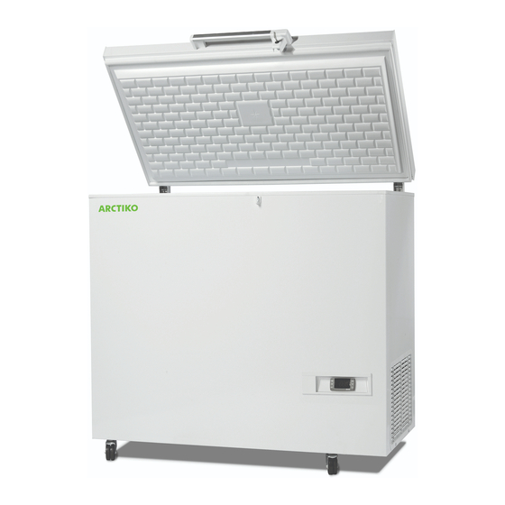
Summary of Contents for Arctiko LTFE 140
- Page 1 OPERATING INSTRUCTIONS LTFE 140 / 290 / 370 / 515...
-
Page 2: Table Of Contents
INDEX PAGE Low Temperature Freezing Box ..........3 Operating Instructions . -
Page 3: Low Temperature Freezing Box
Low Temperature Freezing Box For safety reasons, these operating instructions should be read before the freezer is commissioned. The operating instructions should always be available to and accessible for the personnel! The drawings and symbols in these operating instructions are for safety purposes when commissioning and using the freezer. -
Page 4: Operating Instructions
Operating Instructions The freezer should be connected by an authorised electrician, or by the company which sold the freezer! Incorrect installation may damage the freezer. Place the freezer on a flat floor which can take the weight of the freezer. The electrical installation should be earthed. -
Page 5: Installing The Freezer
Installing the Freezer Connect the plug from the unit to power. If the electrical connection (the plug) has to be changed, always let an authorised electrician install the freezer (read the operation instructions). The freezer should be located in a dry, cool place, out of direct sunlight. The freezer gives off a great deal of heat when in operation. -
Page 6: Control Panel
CONTROL PANEL (Dixell XR30CX Controller) To display target set point; in programming mode it selects a parameter or confirm an operation. (DEF) To start a manual defrost Figure 1 (UP) To see the max. stored temperature; in programming mode it browses the parameter codes or increases the displayed value. (DOWN) To see the min stored temperature;... -
Page 7: Main Functions
HOW TO RESET THE MAX AND MIN TEMPERATURE RECORDED 1. Hold press the SET key for more than 3s, while the max. or min temperature is displayed. (rSt message will be displayed) 2. To confirm the operation the “rSt” message starts blinking and the normal temperature will be displayed. MAIN FUNCTIONS HOW TO SEE THE SETPOINT 1. - Page 8 3. Select the required parameter. 4. Press the “SET ” key to display its value. 5. Use to change its value. 6. Press “SET” to store the new value and move to the following parameter. To exit: Press SET + wait 15s without pressing a key.
-
Page 9: Parameters
PARAMETERS REGULATION Differential: (0,1 ÷ 25,5°C / 1÷255 °F) Intervention differential for set point. Compressor Cut IN is Set Point + differential (Hy). Compressor Cut OUT is when the temperature reaches the set point. Minimum set point: (-100°C ÷ SET; [-148F ÷ SET): Sets the minimum value for the set point. Maximum set point: (SET÷150°C/ SET÷302°F). -
Page 10: Alarms
ALARMS ALC Temperature alarms configuration: (Ab; rE) Ab= absolute temperature: alarm temperature is given by the ALL or ALU values. rE = temperature alarms are referred to the set point. Temperature alarm is enabled when the temperature exceeds the “SET+ALU” or “SET-ALL” values. ALU MAXIMUM temperature alarm: (SET÷150°C;... - Page 11 nPS Pressure switch number : (0 ÷15) Number of activation of the pressure switch, during the “did” interval, before signalling the alarm event (I2F= PAL). If the nPS activation in the did time is reached, switch off and on the instrument to restart normal regulation.
- Page 12 START DEFROST (i1F = dFr) It starts a defrost if there are the right conditions. After the defrost is finished, the normal regulation will restart only if the digital input is disabled otherwise the instrument will wait until the “MdF” safety time is expired.
-
Page 13: Connections
CONNECTIONS XR30CX: 20A COMPRESSOR 12Vac/dc supply: connect to the terminals 7 and 8. 24Vac/dc supply: connect to the terminals 7 and 8. 120Vac supply: connect to the terminals 7 and 8. -
Page 15: Cleaning And Maintenance Of The Freezer
Cleaning and Maintenance of the Freezer Ice on the inside of the box should be removed as required, as it reduces the cooling capacity! Take the contents out of the freezer. Pull out the plug and leave the lid open until the ice can be removed. (Remember safety gloves). -
Page 16: Relocating Or Moving The Freezer
Relocating or Moving the Freezer Never leave the freezer to others without instructing these people in its use and the safety regulations described in the operating instructions. Always let an authorised electrician install the freezer. (Remember to wait for one hour before restarting it). If the freezer and its electrical parts are reconstructed, the guarantee and safety regulations shall cease to apply. -
Page 17: Wiring Diagram
Wiring Diagram... - Page 18 Wiring Diagram...
- Page 19 Wiring Diagram...
- Page 20 WWW.ARCTIKO.COM LAMMEFJORDSVEJ 5 DK-6715 ESBJERG N DENMARK TEL. +45 70 20 03 28 FAX +45 70 20 03 29 INFO@ARCTIKO.COM WWW. ARCTIKO.COM 50 80 018-04-GB...


Need help?
Do you have a question about the LTFE 140 and is the answer not in the manual?
Questions and answers