
Related Manuals for Daikin VRV IV-S RXYSQ6TMYFK


Summary of Contents for Daikin VRV IV-S RXYSQ6TMYFK
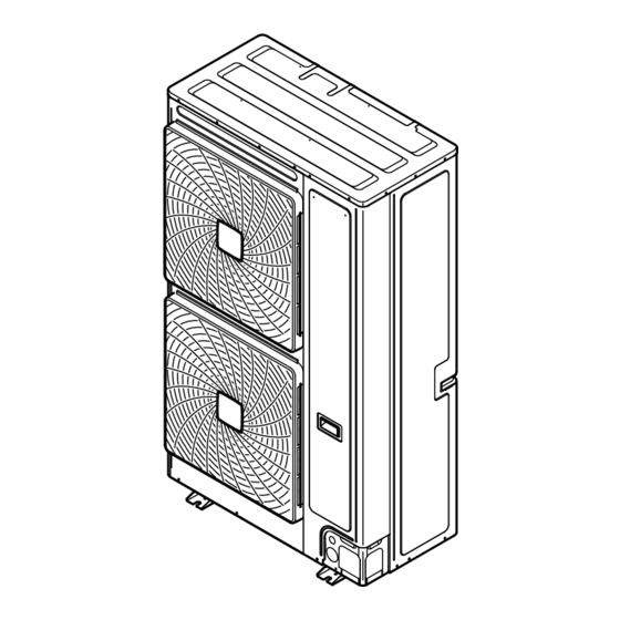
- Page 1 Installation and operation manual VRV IV-S system air conditioner Installation and operation manual English VRV IV-S system air conditioner RXYSQ6TMYFK...
- Page 2 (mm) — ≥100 A, B, C — ≥100 ≥100 ≥100 B, E — ≥100 ≥1000 ≤500 A, B, C, E — ≥150 ≥150 ≥150 ≥1000 ≤500 — ≥500 D, E — ≥1000 ≥1000 ≤500 B, D — ≥100 ≥1000 B, D, E <H ≤½H ≥250...
-
Page 3: Table Of Contents
Table of contents 6.1.4 To access mode 1 or 2 ..........16 Table of contents 6.1.5 To use mode 1 ............. 17 6.1.6 To use mode 2 ............. 17 6.1.7 Mode 1 (and default situation): Monitoring settings ..17 6.1.8 Mode 2: Field settings.......... -
Page 4: About The Documentation
Make sure that the user has the printed documentation and Daikin website (publicly accessible). ask him/her to keep it for future reference. ▪ The full set of latest technical data is available on the Daikin Target audience extranet (authentication required). -
Page 5: System Layout
–5°C for 5 days or longer, with relative humidity levels exceeding 95%, we recommend to apply a Daikin Mind the spacing guidelines. See the "Technical data" chapter, and range specifically designed for such application and/or to the figures on the inside of the front cover. -
Page 6: To Select The Piping Size
4 Preparation Outer diameter Temper grade Thickness (t) (Ø) Ø 6.4 mm (1/4") Annealed (O) ≥0.80 mm 9.5 mm (3/8") 12.7 mm (1/2") Outdoor unit 15.9 mm (5/8") Annealed (O) ≥0.99 mm Main pipes 19.1 mm (3/4") Half hard (1/2H) ≥0.80 mm Increase First refrigerant branch kit 22.2 mm (7/8") Indoor unit 25.4 mm (1") Half hard (1/2H) -
Page 7: Preparing Electrical Wiring
5 Installation Indoor unit capacity index Refrigerant branch kit Mounting the outdoor unit x<200 KHRQ22M29H 5.2.1 To provide the installation structure INFORMATION Prepare 4 sets of anchor bolts, nuts and washers (field supply) as Maximum 8 branches can be connected to a header. follows: Preparing electrical wiring 4.3.1... -
Page 8: To Prevent The Outdoor Unit From Falling Over
5 Installation 2 Insert a hexagon wrench into the stop valve and turn the stop NOTICE valve counterclockwise. If drain holes of the outdoor unit are covered by a mounting 3 When the stop valve cannot be turned any further, stop turning. base or by floor surface, raise the unit to provide a free space of more than 150 mm under the outdoor unit. -
Page 9: To Remove The Pinched Pipes
5 Installation Tightening torques Stop valve Tightening torque N•m (turn clockwise to close) size (mm) Shaft Valve body Hexagonal Cap (valve Service wrench lid) port Ø12.7 8.1~9.9 4 mm 18.0~22.0 11.5~13.9 Ø25.4 27.0~33.0 8 mm 22.5~27.5 5.3.2 To remove the pinched pipes WARNING Any gas or oil remaining inside the stop valve may blow off WARNING... -
Page 10: Checking The Refrigerant Piping
5 Installation 4 Do the following: 6 Seal all gaps (example: a) to prevent snow and small animals from entering the system. ▪ Connect the liquid pipe (a) to the liquid stop valve. (brazing) ▪ Connect the gas pipe (b) to the gas stop valve. (brazing) WARNING NOTICE Provide adequate measures to prevent that the unit can be... -
Page 11: Checking Refrigerant Piping: General Guidelines
5 Installation Leak test and vacuum drying NOTICE Checking the refrigerant piping involves: The connections to the indoor units and all indoor units should also be leak and vacuum tested. Keep any possible ▪ Checking for any leakages in the refrigerant piping. (field supplied) field piping valves open as well. -
Page 12: Charging Refrigerant
5 Installation ▪ Use heat resistant polyethylene foam which can withstand a NOTICE temperature of 70°C for liquid piping and polyethylene foam which Close the front panel before any refrigerant charge can withstand a temperature of 120°C for gas piping. operation is executed. -
Page 13: Error Codes When Charging Refrigerant
5 Installation 3 Pre‑charge refrigerant until the determined additional refrigerant INFORMATION amount is reached or pre‑charging is not possible anymore, and The manual refrigerant charge operation will automatically then close valves C and B. stop within 30 minutes. If charging is not completed after 4 Do one of the following: 30 minutes, perform the additional refrigerant charging operation again. -
Page 14: Connecting The Electrical Wiring
5 Installation NOTICE 5.7.3 Guidelines when connecting the electrical wiring In Europe, the greenhouse gas emissions of the total refrigerant charge in the system (expressed as tonnes CO Tightening torques equivalent) is used to determine the maintenance intervals. Follow the applicable legislation. Wiring Screw size Tightening torque... -
Page 15: Finishing The Outdoor Unit Installation
6 Configuration 6 Reattach the service cover. 7 Connect an earth leakage circuit breaker and fuse to the power supply line. Finishing the outdoor unit installation (A1P) 5.8.1 To finish the transmission wiring After installing the transmission wires inside the unit, wrap them along with the on-site refrigerant pipes using finishing tape, as shown in figure below. -
Page 16: To Access The Field Setting Components
6 Configuration Mode Description Description Mode 2 Mode 2 is used to change the field settings of Mode 1 the system. Consulting the current field setting (field settings) value and changing the current field setting value is possible. Mode 2 In general, normal operation can be resumed without special intervention after changing field settings. -
Page 17: To Use Mode 1
6 Configuration 6.1.5 To use mode 1 Setting Value / Description [1‑1] Unit is currently not operating under low In mode 1 (and in default situation) you can read out some noise restrictions. Shows the status information. Unit is currently operating under low of low noise Example: 7‑segments display –... -
Page 18: Mode 2: Field Settings
6 Configuration Setting Value / Description Setting Value / Description [1‑17] When the latest malfunction codes were reset by [1‑40] For more information, see setting [2‑81]. accident on an indoor unit user interface, they Shows the latest Shows the current can be checked again through this monitoring malfunction code. - Page 19 6 Configuration Setting Value Description [2‑22] 0 (default) Deactivated Level 1 Level 3<Level 2<Level Automatic low noise setting and level during night time. Level 2 By changing this setting, you activate the automatic low noise operation function of the unit and define the level of operation. Level 3 Depending on the chosen level, the noise level will be lowered.
-
Page 20: To Connect The Pc Configurator To The Outdoor Unit
7 Commissioning Setting Value Description [2‑82] 1 (default) Mild Heating comfort setting. Quick This setting is used in conjunction with setting [2‑9]. Powerful 6.1.9 To connect the PC configurator to the Field wiring outdoor unit Be sure that the field wiring has been carried out according to the instructions described in the chapter "5.7 ... -
Page 21: Checklist During Commissioning
8 Troubleshooting Additional refrigerant charge Step Description Communication check The amount of refrigerant to be added to the unit shall be written on the included "Added refrigerant" plate and Stop valve check attached to the rear side of the front cover. Pipe length check Installation date and field setting Pump down operation... -
Page 22: Error Codes: Overview
8 Troubleshooting The error code on the outdoor unit will indicate a main malfunction INFORMATION code and a sub code. The sub code indicates more detailed If a malfunction occurs, the error code is displayed on the information about the malfunction code. The main code and sub outdoor unit's 7‑segments display and on the user interface code will be displayed intermittent (with an interval of 1 ... -
Page 23: Technical Data
Open stop valves. run) Technical data A subset of the latest technical data is available on the regional Daikin website (publicly accessible). The full set of latest technical data is available on the Daikin extranet (authentication required). Overview: Technical data This chapter contains information about: •... -
Page 24: Dimensions: Outdoor Unit
9 Technical data Dimensions: Outdoor unit (dimensions in mm) 3D083088A Gas pipe connection (brazing Ø22.2) Liquid pipe connection (brazing Ø9.5) Service port (high pressure) (in the unit) Service port (refrigerant charge) (in the unit) Earthing terminal M8 (in the switch box) Refrigerant piping intake Transmission wiring intake (knockout hole Ø27) Power supply wiring intake (knockout hole Ø53) -
Page 25: Service Space: Outdoor Unit
9 Technical data Service space: Outdoor unit When mounting units side by side, the piping route must be to the front or downwards. In this case the piping route to the side is not possible. Single unit ( ) | Single row of units ( See figure 1 on the inside of the front cover. -
Page 26: Piping Diagram: Outdoor Unit
9 Technical data Piping diagram: Outdoor unit S1NPH S1NPL S1PH R21T INV M1C Stop valve (gas) Stop valve (liquid) Filter (6×) Subcool heat exchanger Heat sink PCB Pressure regulating valve Heat exchanger Service port (high pressure) Check valve Oil separator Capillary tube (2×) Accumulator Service port (refrigerant charge) -
Page 27: Wiring Diagram: Outdoor Unit
9 Technical data Wiring diagram: Outdoor unit The wiring diagram is delivered with the unit, located at the inside of Magnetic relay (Y2S) (A1P) the service cover. Magnetic relay (E1HC) (A1P) Notes: K11R Magnetic relay (Y1S) (A1P) Reactor This wiring diagram applies only to the outdoor unit. Motor (compressor) Symbols (see below). -
Page 28: Technical Specifications: Outdoor Unit
9 Technical data Technical specifications: Outdoor unit Technical specifications Specification RXYSQ6 Casing material Painted galvanised steel Dimensions h×w×d 1615×940×460 mm Weight 175 kg Operation range ▪ Cooling (min./max.) –5/52°C ▪ Heating (min./max.) –20/15.5°C Cooling T1 ▪ Capacity 15.25 kW / 52000 Btu/h ▪ EER 11.42 Btu/h/W ▪... - Page 29 9 Technical data Specification RXYSQ6 Safety devices High pressure switch Fan driver overload protector Inverter overload protector PCB fuse Nominal cooling capacities are based on: T1: Indoor temperature: 26.7°C DB, 19.4°C WB. Outdoor temperature: 35°C DB. AHRI 1230:2010. Power input indoor units (duct type) included. T3: Indoor temperature: 29.0°C DB, 19.0°C WB.
-
Page 30: Capacity Table: Indoor Unit
9 Technical data Capacity table: Indoor unit Total capacity of indoor units needs to be within the specified range. The connection ratio (CR): 100%≤CR≤130%. HP class of outdoor 100% 130% unit minimum CR maximum CR NOTICE When selecting the total capacity higher than mentioned in above table, cooling and heating capacity will drop. -
Page 31: For The User
10 About the system For the user About the system Operation The indoor unit part of VRV IV-S heat pump system can be used for 12.1 Operation range heating/cooling applications. The type of indoor unit which can be used depends on the outdoor units series. Use the system in the following temperature and humidity ranges for NOTICE safe and effective operation. -
Page 32: To Operate The System
12 Operation into defrost operation to be able to remove frost from the outdoor 12.4.1 About the air flow flap unit’s coil. During defrost operation the heating capacity on the indoor unit side will temporarily drop until defrosting is completed. Double flow+multi-flow units After defrosting, the unit will regain its full heating capacity. -
Page 33: To Designate The Master User Interface (Vrv Dx)
13 Maintenance and service The displays of slave user interfaces show (change-over NOTICE under centralised control) and slave user interfaces automatically Do not wipe the controller operation panel with benzine, follow the operation mode directed by the master user interface. thinner, chemical dust cloth, etc. -
Page 34: 14 Troubleshooting
14 Troubleshooting WARNING Malfunction Measure The system operates ▪ Check if air inlet or outlet of outdoor or ▪ Do not modify, disassemble, remove, reinstall or repair but cooling or heating indoor unit is not blocked by obstacles. the unit yourself as incorrect dismantling or installation is insufficient. -
Page 35: Symptoms That Are Not System Malfunctions
14 Troubleshooting Main code Contents 14.2.1 Symptom: The system does not operate Electronic expansion valve malfunction (outdoor) ▪ The air conditioner does not start immediately after the ON/OFF Discharge temperature malfunction (outdoor) button on the user interface is pressed. If the operation lamp lights, the system is in normal condition. - Page 36 15 Relocation 14.2.7 Symptom: The user interface display 14.2.15 Symptom: The compressor in the outdoor reads "U4" or "U5" and stops, but then unit does not stop after a short heating restarts after a few minutes operation This is because the user interface is intercepting noise from electric This is to prevent refrigerant from remaining in the compressor.
- Page 40 4P524881-1 2018.02...
Need help?
Do you have a question about the VRV IV-S RXYSQ6TMYFK and is the answer not in the manual?
Questions and answers