
Subscribe to Our Youtube Channel
Related Manuals for Sea-doo NAUTICA J-CLASS NZS21


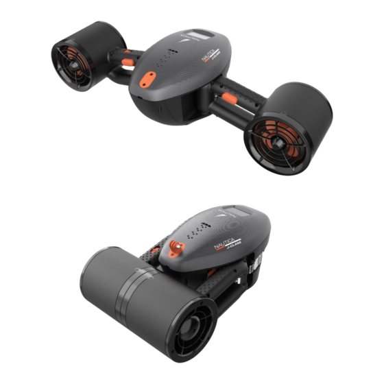
Summary of Contents for Sea-doo NAUTICA J-CLASS NZS21
- Page 1 Distributor Maintenance Manual Date: 17 Apr 2023 Rev.: 02 Model no.: NZS21 J-CLASS NEA22750...
-
Page 2: Table Of Contents
Table of Content 1) Battery Pod Replacement (NZS21B) P4-5 2) Steel Latch Replacement (N21023) P6-7 3) Go Pro Mount Replacement (N21018) Multipurpose Mount Replacement (N21002) 4) Rear Housing Replacement (N21011) P9-13 Rear Housing Foam Replacement (N21012) ------ Top Cap Replacement (N21007) ------ Top Cap Foam Replacement (N21008) ------... - Page 3 Tools required for repairing.
-
Page 4: Battery Pod Replacement (Nzs21B) P4-5
NZS21 - J-CLASS NEA22750 Section 1 - Battery Pod Replacement (NZS21B) Unscrew rear housing knob and slide up to remove rear housing Flip out two battery pod latches to unlock battery pod... - Page 5 Grip battery pod handle to pull battery pod out Change by fully charged battery pod, add sealing grease over 4 seal ring surfaces Slide in battery pod with guiding slot facing bottom of seascooter Press two latches down to lock battery pod in place Slide rear housing back down Turn rear housing knob clockwise to lock rear housing...
-
Page 6: Steel Latch Replacement (N21023)
NZS21-J-CLASS NEA22750 Section 2 - Steel Latch Replacement (N21023) Unscrew 2 mounting screws and remove latch body Unscrew 2 mounting screws and remove hook piece... - Page 7 Replace new latch body placing between 2 guiding ribs Replace new hook piece placing within the 3 guiding ribs Fasten 2 mounting screws to hold hook piece in place...
-
Page 8: Multipurpose Mount Replacement (N21002) P8
NZS21-J-CLASS NEA22750 Section 3 GoPro Mount (N21018) and Multipurpose Mount (N21002) Replacement GoPro Mount (N21018) Multipurpose Mount (N21002) Unscrew 2 mounting screws to take out GoPro Replace new GoPro camera mount or change camera mount to multipurpose mount. MAKE SURE the indexing key slot is matched. Fasten 2 mounting screws to hold the mount in place... -
Page 9: Rear Housing Replacement (N21011)
NZS21-J-CLASS NEA22750 Section 4 Rear Housing Replacement (N21011) Rear Housing Foam Replacement (N21012) Top Cap Replacement (N21007) Top Cap Buoyancy Foam Replacement (N21008) Bottom Cap Replacement (N21003) Bottom Cap Buoyancy Foam Replacement (N21004) Battery Support Replacement (N21006) Rear Housing (N21011) Top Cap Buoyancy Foam Rear Housing Foam Top Cap (N21007) - Page 10 Unscrew rear housing knob and slide up to remove rear housing Unscrew to remove rear housing buoyancy foam Replace new rear housing buoyancy foam and fasten 2 mounting screws...
- Page 11 Unscrew 4 top cap mounting screws and undo 2 side latches to remove top cap Take out top cap buoyancy foam Unscrew 4 mounting screws to remove bottom cap...
- Page 12 Remove bottom cap buoyancy foam Unscrew 8 mounting screws to take out battery support bracket Replace new battery support bracket and fasten 8 mounting screws to hold Replace new bottom cap buoyancy foam...
- Page 13 Replace new bottom cap and fasten 4 mounting Replace new top cap buoyancy foam screws to hold Replace new top cap and press both sides down to Fasten 4 mounting screws to hold top engage two latches cap in place Slide down rear housing and fasten locking knob clockwise to hold...
-
Page 14: Handle Top Right Cover Replacement (N21021)
NZS21-J-CLASS NEA22750 Section 5 Handle top right cover replacement (N21021) Handle top left cover replacement (N21027) Handle left top foam replacement (N21026) Right trigger module replacement (N21019) Left trigger module replacement (N21024) Handle top right cover (N21021) Handle top left cover (N21027) Handle left top foam (N21026) Right trigger module (N21019) Left trigger module (N21024) - Page 15 Unscrew to remove LR handle top covers Take out handle top left foam Unscrew right trigger module Unscrew left trigger module...
- Page 16 Take out right trigger module and take out right sensor from module slot. DO NOT damage sensor cable Take out master switch sensor from module Replace new right trigger and master switch slot. DO NOT damage sensor cable module Pass master switch sensor through the hole and lay down on slot then tidy up cable...
- Page 17 Fit right trigger module down through 2 screw Fasten 2 mounting screws to lock right trigger posts module in place Fit right trigger sensor to slot and tidy up Replace new handle top right cover and fix it by 4 sensor cable mounting screws Fit left trigger sensor to the slot of new left trigger module and tidy up sensor cable...
- Page 18 Fit left trigger module down through 2 screw posts Fasten 2 mounting screws to lock left trigger module in place Fit new handle left top foam in place Replace new handle top left cover and fix it by 4 mounting screws...
-
Page 19: Nozzle Rear Grille Replacement (N21013)
NZS21-J-CLASS NEA22750 Section 6 Nozzle Rear Grille Replacement (N21013) Left (N21025)/ Right (N21020) Nozzle Foam Replacement Left (N21028)/ Right (N21029) Nozzle Front Grille Replacement Propeller Replacement (N21041) Propeller (N21041) Nozzle Rear Grille (N21013) Left (N21028)/ Right (N21029) Nozzle Front Grille Left (N21025) Nozzle Foam Set Right (N21020) Nozzle Foam... - Page 20 Unscrew and take out right nozzle rear grille Slide out rear nozzle buoyancy foams those with debossment R1, R2 and R3 Unscrew right nozzle front grille and pull out...
- Page 21 Hold the propeller and use nut driver to unscrew propeller nylock nut Ensure propeller drive pin is located equal lengths on either side of propeller shaft Replace new propeller with drive pin slot in line with propeller drive pin Fasten nylock nut to lock propeller in place DO NOT over tighten the nylock nut, it'll bend the drive pin...
- Page 22 Replace new right nozzle buoyancy foams marked with R1, R2 and R3 MAKE SURE positions and orientations are all correct...
- Page 23 Install new right nozzle rear grille with ribs pointing to the motor cable slot Fasten rear grille mounting screws to lock rear grille in place Push new right nozzle front grille back (engraved with R) ENSURE engraving R matches and grille's orientation is correct Fasten mounting screws back to lock front grille in place...
- Page 24 Repair left grilles, left buoyancy foams and left side propeller follows the same procedures. Reminder : 1. Front grille engraved with L is for left side, R is for right side. 2. Front grilles indexing post constraints orientation of front grilles when installing front grilles back to the nozzles.
-
Page 25: Bottom Housing Face Seal Replacement (N21009)
NZS21 - J-CLASS NEA22750 Section 7 7-1 Bottom Housing Face Seal Replacement (N21009) 7-2 Leakage Sensor Bracket Replacement (N21015) 7-3 Bottom Housing Foam Replacement (N21005) 7-4 Power EMI Suppression Core Inductor Replacement (N21041) 7-5 Main Board Housing Seal Replacement (N21010) 7-6 Motor EMI Suppression Core Inductor Replacement (N21040) 7-7 Positive (N21032) / Negative (N21033) Power Wire Replacement 7-8 LED Board Cable Replacement (N21031) - Page 26 Positive Power Wire (N21032) Negative Power Wire (N21033) LED Board Cable (N21031) LED Board (N21038) LED Housing (N21001)
- Page 27 7-1 Bottom Housing Face Seal Replacement (N21009) Unscrew rear housing knob and slide up to remove rear housing Flip out two battery pod latches to unlock battery pod Grip battery pod handle to pull battery pod out Unscrew 4 top cap mounting screws and undo 2 side latches to remove top cap...
- Page 28 Take out top cap and top cap buoyancy foam Unscrew 16 mounting screws to take out controller module Remove damaged bottom housing seal and replace Add sealing grease to the seal ring groove on Replace new bottom housing seal, sit seal ring bottom housing.
- Page 29 Add sealing grease all over Tidy up left right cables for transparent module to cover down seal ring surface. over bottom housing. Fasten 16 screws to seal up transparent Check seal ring compression mark through module with bottom housing. transparent housing. 7-2 Leakage Sensor Bracket Replacement (N21015) Press the V hook and pull out leakage sensor bracket.
- Page 30 Pass mounting screws through sensor cable terminals to fix sensor cables to sensor bracket Slide leakage sensor bracket back down along the slots until it is latched by the V hook. Section 7-3-Bottom Housing Foam Replacement Use tweezers to take out bottom housing Replace new bottom housing foam 2 foam 2 from right handle side.
- Page 31 Section 7-4-Power EMI Suppression Core Inductor Replacement Unclip power EMI suppression inductors and remove. Replace new power EMI suppression inductors, add glue to the slots. Clip back new power EMI suppression inductors not too far away from transparent module. Section 7-5-Main Board Housing Seal Replacement Unscrew 14 screws to open main board housing, keep the screws for re-assemble.
- Page 32 Remove main board housing seal. Add grease to the seal ring groove on main Replace new main board housing seal ring board top housing. to the seal ring groove Add sealing grease along the seal ring Tidy up cables to avoid supporting ribs surface.
- Page 33 Section 7-6-Motor EMI Suppression Core Inductor Replacement Unclip motor EMI suppression inductors and remove. Replace new motor EMI suppression inductors to the middle length of cables and clip to lock. Add glue to fix the inductors in places. Section 7-7-Positive and negative power wire replacement Use A/F 2.5mm allen key to unscrew positive cable, make sure to keep tooth washers and socket head screws to fix new cable.
- Page 34 Change new positive cable, socket head screw through tooth washer and 2 red cable terminals then tighten back to main board positive terminal post. Socket head screw through tooth washer and red cable terminal then tighten back to driver board positive terminal post. Align cable between guiding ribs. Use A/F 2.5mm allen key to unscrew negative cable, make sure to keep tooth washers and socket head screws to fix new cable.
- Page 35 Socket head screw through tooth washer and black cable terminal then tighten back to driver board negative terminal post. Align cable between guiding ribs. Section 7-8-LED Board-LED Housing-LED Board Cable Replacement Unscrew LED board and remove. Remove LED housing. Replace new LED housing with flat surface facing out.
- Page 36 Fasten 2 mounting screws back to lock LED board in place. Replace new LED board cable, plug sockets with correct orientation (socket pins are shifted). Add glue to fix plug/socket not to wobble and move.
-
Page 37: Top Housing Module Replacement (N21017)
NZS21 - J-CLASS NEA22750 Section 8 8.1 Top Housing Module Replacement (N21017) 8.2 Main Board Replacement (N21036) 8.3 Main Board & Driver Board Cable Replacement (N21034) 8.4 LCD Board Cable Replacement (N21031) 8.5 LCD Display Board Replacement (N21037) 8.6 LCD Backlight Blocking Sheet Replacement (N21022) Top Housing Module (N21017) Main Board (N21036) LCD Backlight Blocking Sheet (N21022) - Page 38 8.1 Top Housing Module Replacement (N21017) Unplug LCD cable and drive board cable Unscrew and take out LED board Take out LED housing. Unscrew 8 socket headed screws, All cables are disconnected keep the screws and tooth washers. from top housing module. Top housing module is completely Replace new top housing module disconnected for replacement...
- Page 39 8 socket headed screws through tooth Make sure socket headed screws through washers and cable terminals then tighten tooth washers and cable terminals back to driver board connection posts. Align cable between guiding ribs. Plug 6P LCD cable and 8P drive board Plug sockets with correct orientation cables back and glued to fix.
- Page 40 Fasten 14 screws back to seal main board housing. 8.2 Main Board Replacement (N21036) Unplug LCD/LED/Drive board cables on main board, unscrew power cables and keep screws and tooth washers for reassemble. Unscrew main board 4 mounting screws. Unlatch 16P plug and pull out to disconnect main board. Replace new main board.
- Page 41 Plug back cables and glue plug/socket to avoid Slide switch pointing to 16P socket to turn to loose. operation mode. Add sealing grease along the seal ring surface. Tidy up cables to avoid supporting ribs puncture cables when closing back the housing Fasten 14 screws back to seal main board Check seal ring path misalignment through housing.
- Page 42 8.3 Main Board & Driver Board Cable Replacement (N21034) 8.4 LCD Board Cable Replacement (N21031) Unplug cable both sides to remove cable. Replace new cables and pay attention to plug’s orientation matched with sockets. Add glue to avoid plug/socket loose. Add sealing grease along the seal ring surface.
- Page 43 8.5 LCD Display Board Replacement (N21037) 8.6 LCD Backlight Blocking Sheet Replacement (N21022) Unplug LCD cable and cut Take out sealing sheet and Unscrew to remove LCD silicone glue along red line. scrap, clean residual silicone board. glue on top housing. Change blocking sheet.
- Page 44 Add sealing grease along the seal ring surface. Tidy up cables to avoid supporting ribs puncture cables when closing back the housing Fasten 14 screws back to seal main board Check seal ring path misalignment through housing. transparent housing.
-
Page 45: Brushless Motor Replacement (N21039)
NZS21 - J-CLASS NEA22750 Section 9 Brushless Motor (Left) Replacement (N21039) Brushless Motor (N21039) CAN DO THE SAME ON RIGHT MOTOR IF FEASIBLE ! Unscrew to remove left handle Take out handle cover and Add markings at three 14 top cover. buoyancy foam. - Page 46 Unscrew to remove left Unscrew motor mounting Take out defective motor from nozzle rear cap. screws, keep spring washers nozzle back. and screws for re-assemble. Copy cable markings to Install new motor to the nozzle, Fasten motor mounting screws the good motor at same make sure orientation and dowel with spring washers back to fix distances.
- Page 47 Clip in nozzle front cap, make Cut cable 1 with matched Strip cable 1 get ready for sure orientation is correct and length for connection. soldering. then fasten 2 screws. Soldering both sides of Insert GLUED heat shrink Soldering to connect cable 1. stripped cable 1.
-
Page 48: Activate Bt For Software Upgrade And Product Diagnosis P48-49
NZS21 - J-CLASS NEA22750 Section 10 Activate BT for software upgrade and product diagnosis 10.1 Install IPA document to your iPhone to get latest version SMACIRCLE APP, MAKE SURE the software is 8124 or newer version. You should see an APP icon like this once installed APP properly 10.2 MAKE SURE J-Class’s battery is charged enough to do software upgrade and diagnosis. - Page 49 10.6 Refer to following procedures to pair BT/Seascooter, read diagnosis data, upgrade software and quit. Tap SMACIRCLE1024 Tap icon to get in Upgrade software and read diagnosis data. Software upgrading Upgrade finish and tap 返回 icon to quit. to pair diagnosis page.
-
Page 50: Error Codes / Descriptions / Actions P50
NZS21 - J-CLASS NEA22750 Section 11 Error codes / descriptions / actions Error Code Description Action Motor ON/OFF error Release triggers, OFF and ON master switch again to retry. Motor right driver not receive control signal Check connection cables between main board and motor drive board.
Need help?
Do you have a question about the NAUTICA J-CLASS NZS21 and is the answer not in the manual?
Questions and answers