
Subscribe to Our Youtube Channel
Related Manuals for Prozeda primos 600 SR


Summary of Contents for Prozeda primos 600 SR
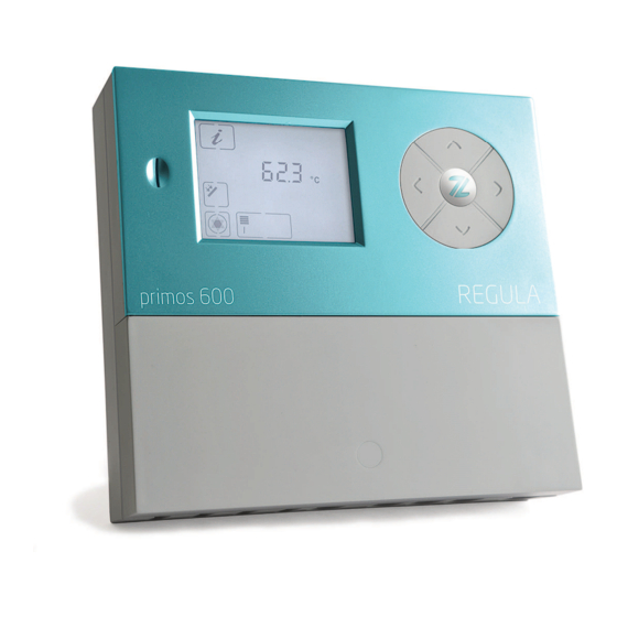
- Page 1 Controller unit for solar thermal systems primos 600 SR Installation and operating instructions English version of original German installation and operating instructions Version: 1.4 June 2016...
- Page 2 • These installation and operating instructions will hereinafter be designated as "Instructions". • The primos 600 SR controller will hereinafter be designated as "Controller". • The thermal solar power plant will hereinafter be designated as "Solar power plant". • Freely definable Prozeda function modules, complete with selectable inputs and outputs, will hereinafter be designated as "Multi-function controllers"...
- Page 3 This manual is designed to help you use the controller properly, safely and economically. Target group This manual is addressed to all persons who carry out any of the following tasks: • Installing the controller • Connecting the controller • Putting the controller into operation •...
- Page 4 Style conventions used in the text Specific style conventions are assigned to different elements in the manual. This makes it easy to recognise the type of text concerned: Standard text, "Menu", "Menu item", "Button designations", • lists and actions. Notes accompanied by this symbol contain information about how to operate the controller economically.
-
Page 5: Table Of Contents
Table of contents Safety ........................7 1.1 Proper use .............................. 7 1.2 Basic safety information ........................7 Description of the controller ................... 9 2.1 Overview ..............................9 Installing the controller ..................10 3.1 Removing the terminal cover ......................11 3.2 Fastening the controller ........................12 Connecting the controller .................. - Page 6 10.5 Setting the "Drain-back" function ....................46 10.6 Setting the "Anti-freeze protection" function ................47 11 Measuring energy output ..................48 11.1 Flow sensor (DFG) ..........................48 11.2 VFS (Vortex Flow Sensor) ......................... 48 11.3 Flow indicator............................48 11.4 Setting the energy output measurements................. 49 12 Restore factory settings ..................
-
Page 7: Safety
• Use the RS485 interface (ProBusX) only for networking further devices from the manufacturer Prozeda. The definition of proper use also encompasses observing and complying with all of the information contained in this manual - in particular compliance with all safety information and instructions. - Page 8 Safety Preventing risks of fatal injury from electric shocks • Make sure that all regulations applicable at the point of use are complied with. • Always make sure that the controller is disconnected from the power supply before carrying out any work on it. •...
-
Page 9: Description Of The Controller
Description of the controller • Use only sensor connection boxes supplied by the manufacturer. 2 Description of the controller The controller is used for monitoring and controlling a solar thermal system. The controller allows the system to be configured in accordance with the local situation at the place of use and with the requirements of the user. -
Page 10: Installing The Controller
Installing the controller 3 Installing the controller DANGER Risk of fatal injuries due to explosions or fire. Never use the controller in areas where there is a risk of explosion. Install the controller on a non-flammable subsurface. DANGER Risk of fatal electric shock when working on the opened controller. Make sure that the controller is disconnected from the mains voltage before removing the terminal cover. -
Page 11: Removing The Terminal Cover
Installing the controller Removing the terminal cover Undo the locking screw (1). To remove the terminal cover (2), pull it off as shown here. -
Page 12: Fastening The Controller
Connecting the controller Fastening the controller If you wish to lead cables and lines through the back of the controller, you need to do this before you fasten it. ATTENTION Risk of damage to the controller housing due to screws tightened too firmly. -
Page 13: Connecting The Controller
Connecting the controller 4 Connecting the controller DANGER Risk of fatal electric shock when working on the opened controller. Make sure that the controller is disconnected from the mains voltage before removing the terminal cover. Make sure that the power supply has been secured to prevent it from being switched on again. - Page 14 Connecting the controller The following illustration shows the elements of the controller that are important for connection: Pos. Description Terminals for extra-low voltage area Fuse Terminals for 230 V area Terminals for protective conductor Terminals for relay contact Cut-out apertures for cable feedthrough at the back Screw clamps for securing the cables Cut-out apertures for cable feedthrough on the underside Connect the cables to the corresponding terminals.
-
Page 15: Connecting The Controller To The Power Supply
Connecting the controller Connecting the controller to the power supply When making the mains connection, you must ensure that the mains supply can be disconnected at any time. If you make a permanent mains connection, proceed as follows: Install a switch outside the controller. If you make the mains connection complete with cable and earthing pin plug, proceed as follows: Make sure that the earthing pin plug is easily accessible. -
Page 16: Assignment Of The Terminals To The System Components
Assignment of the terminals to the system components 5 Assignment of the terminals to the system components The connections in the following table are options that may be used in all hydraulic layouts: Terminal S4 / S4 Temperature sensor for the collector return for the "Energy output measurement" function S6 / S6 Temperature display... - Page 17 Assignment of the terminals to the system components Terminal assignment for hydraulic layouts 110.00, 111.00, 112.00 110.00 111.00 112.00 Terminal R1 / N / PE Solar circuit pump, 230 V connection. Power control for high-efficiency pump on HE1/M1 (R2 / N / PE) 111.00: Secondary pump.
- Page 18 Assignment of the terminals to the system components Terminal assignment for hydraulic layouts 210.01, 211.01, 212.01 210.01 Alternativ: 2-loading zones 211.01 Alternativ: stratification Terminal R1 / N / PE Solar circuit pump, 230 V connection. Power control for high-efficiency pump on HE1/M1 R2 / N / PE 210.01: Three-way valve 211.01: Secondary pump.
- Page 19 Assignment of the terminals to the system components Terminal assignment for hydraulic layout 210.02 210.02 Alternative: stratification Terminal R1 / N / PE Solar circuit pump, 230 V connection. Power control for high-efficiency pump on HE1/M1 R2 / N / PE Solar circuit pump, 230 V connection.
- Page 20 Assignment of the terminals to the system components Terminal assignment for hydraulic layouts 120.01, 121.01 120.01 121.01 Terminal R1 / N / PE Solar circuit pump, 230 V connection. Power control for high-efficiency pump on HE1/M1 R2 / N / PE 120.01: Three-way valve 121.01: Secondary pump.
- Page 21 Assignment of the terminals to the system components Terminal assignment for hydraulic layout 120.02 120.02 Terminal R1 / N / PE Solar circuit pump, 230 V connection. Power control for high-efficiency pump on HE1/M1 R2 / N / PE Solar circuit pump, 230 V connection. Power control for high-efficiency pump on HE2/M2 S1 / S1 Temperature sensor for collector...
- Page 22 Assignment of the terminals to the system components Terminal assignment for hydraulic layout 000.00 In layout 000.00 you can use all outputs as multi-function controllers. In this case you must define at least one of the three switching outputs R1, R2 or R3 as a multi-function controller. Terminal R1 / N / PE Multi-function controller on switching output R1...
-
Page 23: Operating The Controller
Operating the controller 6 Operating the controller This chapter provides you with an overview of the controller's display elements and operating elements. This is followed by explanations of all the basic actions. Description of the display elements The main menu is located in the top part of the display. It is comprised of the following menus: Main menu Symbol... - Page 24 Operating the controller When you have selected a menu, the applicable menu symbol (1) will be displayed. The bottom section of the screen displays the value (3) complete with a corresponding addition (2) and a measurement value symbol (7). Below these, status information and messages may be displayed (4–6), depending on the specific menu item.
-
Page 25: Using The Operating Buttons
Operating the controller Using the operating buttons The operating buttons allow you to navigate in the menus and make changes to values. The following table explains the functions of the operating buttons: Operating Function buttons Display the previous menu item. Increase the displayed value. -
Page 26: Displaying And Changing The Values In The Menus
Displaying and changing the values in the menus Changing values To activate the displayed menu item, select The value flashes. To increase the value, select To reduce the value, select To cancel the entry, select The value stops flashing. The value that is currently set will be displayed. To confirm the entry, select The value stops flashing. - Page 27 Displaying and changing the values in the menus „Info“ menu Example Symbol Description Reset 75 °C Current temperature of collector – min. 12 °C Minimum temperature of collector × max. 105 °C Maximum temperature of collector × 75 °C – min.
-
Page 28: Displaying And Changing Values In The "Program" Menu
Displaying and changing the values in the menus „Info“ menu Example Symbol Description Reset 1234 h Operating hours for charging To 0 h 8.4 l Current flow – 927 kWh Energy output for the storage tank To 0 kWh To reset a value, proceed as follows: Select The OK symbol will be displayed. - Page 29 Displaying and changing the values in the menus „Program“ menu Value Symbol Description Range Factory Current setting setting max. 65 °C Storage tank: Required maximum 15–95 °C 65 °C temperature dT max 7 K Storage tank: Switch-on- 3–40 K difference dT min 3 K Storage tank: Switch-off- 2–35 K...
- Page 30 Displaying and changing the values in the menus The following eight menu items apply to multi-function controllers R1, R2, R3 and R4. If a hydraulic layout has been selected in the "Basic settings" menu that allows for several multi-function controllers, these menu items will appear several times (once for each multi-function controller).
-
Page 31: Controlling Switching Outputs In The "Manual Mode" Menu
Displaying and changing the values in the menus The following menu items are applicable on a general basis: Start 06:00 Time window 4: Start for the 00:00–23:59 6:00 "Tube collector" and "Drain-back" functions. Only if the time controller has been activated for these functions in the "Basic settings"... -
Page 32: Displaying And Changing Values In The "Basic Settings" Menu
Displaying and changing the values in the menus "Manual mode" menu Symbol Description Current settings Turning switching output R1 or HE1 on or off manually or 0% = off controlling it with incremental power control (30%-90%) 30% – 90 % 100% = on Turning switching output R2 or HE2 on or off manually 0% = off... - Page 33 Displaying and changing the values in the menus To activate editing mode, press the buttons simultaneously. The menu symbol will be displayed in the form of an "unlocked" symbol. Editing mode will be active. Note the following information in relation to the table on the menu items in the "Basic settings"...
- Page 34 Displaying and changing the values in the menus „Basic settings“ menu Position Symbol Description Range Factory Current settings settings "Recooling" function 0–1 P: 8: 0 = Off 1 = On Only if the "Collector protection" function has been activated. P: 9: Temperature to which the storage tank 30–90 °C 40 °C...
- Page 35 Displaying and changing the values in the menus „Basic settings“ menu Position Symbol Description Range Factory Current settings settings P: 17: Energy output measurement: 0–100 % Glycol concentration (in 5 % increments) „Anti-freeze protection“ function 0–1 P: 18: 0 = Off 1 = On P: 19: "Anti-freeze protection"...
- Page 36 Displaying and changing the values in the menus „Basic settings“ menu Position Symbol Description Range Factory Current settings settings P: 29: Selection of the sensor for the sink for 1–6 MFC R3 MFC R4 function at switching 0–3 P: 30: output R0 0 = Off 1 = Cooling...
-
Page 37: Setting The Control Functions
Setting the control functions * Position 16: Glycol types Selection Meaning Selection Meaning Anro Tyfocor L5.5 Ilexan E, Glythermin Dowcal 10 Antifrogen L Dowcal 20 Antifrogen N Dowcal N Ilexan E Tyfocor LS Ilexan P Water * Positions 33 und 34: Pump types Selection Meaning Standard pump, operated with alternating current (AC pump) -
Page 38: Setting The "Storage Tank Priority" Function
Setting the control functions "Target temperature" charging principle In the case of the "Target temperature" charging principle, the solar circuit pump is switched on when a certain specific target temperature has been reached in the collector. The "Program" menu allows you to set the following parameter: •... -
Page 39: Setting The Pump Control System
Setting the control functions The "Program" menu allows you to set the following parameter: • Temperature difference for the "Parallel charging" function. Setting the pump control system You can connect standard pumps and high-efficiency pumps (HE pumps). For these you can set the following types of control system: •... - Page 40 Setting the control functions The following diagram shows the power curve for the pump control system with analog signal. n (%) – Pump output U (V) – Output voltage Controlling HE pumps with PWM signals In the case of the pump control system with PWM signal, the controller sends a PWM signal (pulse width modulation signal) to terminals HE1 and HE2.
-
Page 41: Setting The "Tube Collector" Functions
Setting the control functions PWM (%) – inverted PWM signal n (%) – pump speed sent by the controller Setting the "Tube collector" functions If the solar power system is equipped with tube collectors, you have to activate this function. The control type is selected in the "Basic settings"... -
Page 42: Setting Multi-Function Controllers (Mfc)
Setting multi-function controllers (MFC) 9 Setting multi-function controllers (MFC) Depending on the hydraulic layout, switching outputs R0, R1, R2 and R3 can be used as multi-function controllers (MFC). These can be set irrespective of the basic functions of the controller. You can assign the following functions to the multi-function controllers: •... -
Page 43: Setting The "Heating" Function
Setting multi-function controllers (MFC) Setting the "Heating" function In the case of the "Heating" function, the switching output of the multi-function controller switches on as soon as the temperature falls below the preset switch-on temperature. If the temperature rises above the upper limit of the preset temperature range (hysteresis), the switching output of the multi-function controller switches off. -
Page 44: Setting The "Temperature Difference Controller" Function
Setting multi-function controllers (MFC) • Maximum temperature Tmax of the sink for the " Return flow boost" function • Minimum temperature Tmin of the source for the " Return flow boost" function • Switch-on difference dTmax for the " Return flow boost " function •... -
Page 45: Setting Protective Functions
Setting protective functions 10 Setting protective functions In order to protect the solar power system against frost and overheating, the controller is equipped with the following protective functions: • "Collector protection" function • "Storage tank protection" function • "System protection" function •... -
Page 46: Setting The "Recooling" Function
Setting protective functions When the temperature falls below the system protection temperature, the system will be in the "Collector protection" function again. When the temperature falls below the collector protection temperature, the system will be in normal operating mode. 10.4 Setting the "Recooling" function ATTENTION Risk of damage to the solar power system if operated with the "Recooling"... -
Page 47: Setting The "Anti-Freeze Protection" Function
Measuring energy output The control type is selected in the menu "Basic settings" with the following value: • P:5: "Collector protection" function − "Drain-back" time-controlled function − "Drain-back" radiation-controlled function Time-controlled You can set a time window and a pump runtime. In the time window the solar circuit pump is switched on at certain specific intervals for the duration of the preset pump runtime. -
Page 48: Measuring Energy Output
Measuring energy output 11 Measuring energy output The controller can calculate and display the energy output of the solar power system. To do so, it requires the following values: • Flow rate • Temperature difference between the collector and collector return flow temperatures •... -
Page 49: Setting The Energy Output Measurements
Restore factory settings l/min 11.4 Setting the energy output measurements The "Basic settings" menu allows you to set the following parameters: • P:12: Measurement principle for energy output measurement • P:13: Pulse value of the flow sensor • P:14: VFS type •... -
Page 50: Faults
Faults • Viewing the controller's data on another device (monitoring) • Operating the controller from another device (remote control) The manufacturer can provide further details. 14 Faults ATTENTION Risk of damage to the system if faults are remedied incorrectly. Make sure that faults are only ever remedied by specialist personnel. There are two categories of system faults: •... - Page 51 Faults The table below shows the faults with fault messages: Fault message Possible cause Action A sensor line is interrupted. Make sure that the sensor lines Here S2 are intact. A sensor is faulty. Check the sensor resistance. If necessary, replace the sensor. flashing A short circuit has occurred in Make sure that the sensor lines...
-
Page 52: Faults Without Fault Message
Faults 14.2 Faults without fault message The table below shows the faults without fault messages: Fault Possible cause Action No indication on the display. There is no mains voltage. Switch on the controller or connect the controller to the mains voltage. Make sure that the main fuse for the mains connection is switched on. - Page 53 Technical data Fault Possible cause Action The pump symbol rotates The connection to the pump Make sure that the cable without the pump actually has been interrupted. connection to the pump is running. intact. The pump has seized up. Make sure that the pump is running.
-
Page 54: Technical Data
Technical data 15 Technical data Autonomous electronic temperature difference controller, continuous operation Housing material 100% recyclable ABS housing Dimensions L x W x D in mm 176 × 162 × 44 Protection class IP30 according to DIN 40050, EN 60529 Operating voltage AC 230 voltage, 50 Hz, –10 to +15% Standby power consumption... -
Page 55: Resistance Table
Resistance table 16 Resistance table With reference to the table below check the functioning of the temperature sensors using a resistance meter: Temperature in °C / Resistance in ohms –10 °C 0 °C 10 °C 20 °C 40 °C 60 °C 80 °C 100 °C 960 Ω... -
Page 56: Disposing Of The Controller
Disposing of the controller 18 Disposing of the controller The environmentally-friendly disposal of electronic assemblies, recyclable materials and other unit components is regulated by national and regional laws. Contact the competent local authority for detailed information on disposal. Dispose of lithium batteries in accordance with the statutory regulations. Dispose of all components in accordance with statutory regulations. - Page 60 These instructions were prepared by a technical documentation office certified by DocCert- System. Address of manufacturer Prozeda GmbH In der Büg 5 D-91330 Eggolsheim Telephone: +49(0)9191/6166-0 Telefax: +49(0)9191/ 6166-22 Email: kontakt@prozeda.de www.prozeda.de 1334B-TB001-14B-E...
Need help?
Do you have a question about the primos 600 SR and is the answer not in the manual?
Questions and answers