Advertisement
Quick Links
Certified technicians or those individuals
!
WARNING
meeting the requirements specified by
NATE may use this information. Property
and product damage or personal injury hazard may occur
without such background.
All power sources should be disconnect-
WARNING
!
ed prior to servicing. Failure to do so may
cause personal injury or property dam-
age.
Product designed and manufactured to
WARNING
!
permit installation in accordance with lo-
cal and national building codes. It is the
installer's responsibility to ensure that product is installed
in strict compliance with national and local codes. Manufac-
turer takes no responsibility for damage (personal, product
or property) caused due to installations violating regula-
tions. In absence of local/state codes, refer to National Elec-
tric Code: NFPA 90A & 90B Uniform Mechanical Code.
When this unit is installed in an enclosed
!
WARNING
area, such as a garage or utility room with
any Carbon Monoxide producing devices
(i.e. automobile, space heater, water heater etc.) ensure that
the enclosed area is properly ventilated.
Only factory authorized kits and acces-
!
CAUTION
sories should be used when installing or
modifying this unit unless it is so noted in
these instructions. Some localities may require a licensed
installer/service personnel.
Unit is not approved for outdoor installa-
WARNING
!
tions.
The unit is designed for operation with
WARNING
!
208/240 V, single phase, 60 Hz power
supply. Aspen will not be responsible for
damages caused due to modification of the unit to operate
with alternative power sources.
AEU & AED Series - Manufactured Housing
1. Safety Instruction
Potential safety hazards are alerted using the following symbols. The symbol is used in conjunction with terms
that indicate the intensity of the hazard.
`
WARNING
!
This symbol indicates a potentially hazardous situation, which if not avoided,
could result in serious injury, property damage, product damage or death.
!
This symbol indicates a potentially hazardous situation, which if not avoided,
CAUTION
may result in moderate injury or property damage.
INSTALLATION GUIDE
Electric Furnace Kit
2. Inspection
ü On receiving the product, visually inspect it for any major shipping
related damages. Shipping damages are the carrier's responsibility.
Inspect the product labels to verify the model number and options
are in accordance with your order. Manufacturer will not accept dam-
age claims for incorrectly shipped product.
3. Installation Preparation
Read all the instructions in this guideline carefully while paying spe-
cial attention to the WARNING and CAUTION alerts. If any of the
instructions are unclear; clarify with certified technicians. Gather all
the tools needed for successful installation of the unit prior to begin-
ning the installation.
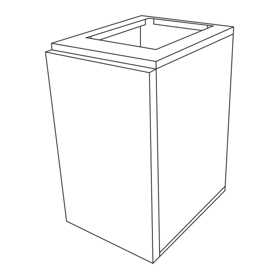
3A. Clearances
This unit is designed for zero clearance installation on three sides
and adequate clearance to provide access for service in the front. A
minimum of 18" (alcove) or 6" (closet) clearance is recommended on
the front end (Fig 3A-1).
6" for Closet
18" for Alcove
Fig 3A-1. Minimum Clearance for Electric Furnace
For closet installation, the return air opening can be on the front door,
above the furnace casing on a wall, or on the electric door's louvered
door (If applicable.)
A minimum clearance of six inches is required, on the return side, in
order to allow for proper airflow.
1
0"
6"
0"
Advertisement

Related Manuals for Aspen AEU Series


Summary of Contents for Aspen AEU Series
- Page 1 208/240 V, single phase, 60 Hz power door (If applicable.) supply. Aspen will not be responsible for damages caused due to modification of the unit to operate A minimum clearance of six inches is required, on the return side, in with alternative power sources.
- Page 2 3B. Closet and Alcove Installation 3B-2. AED-001 (Front Return Only) Configuration Mount coil cabinet on top of electric furnace and secure both unit Ensure that the unit is adequately sized. CAUTION with the Alignment Plates (Figure 3B-2). There are pre-holes on The tonnage of the outdoor unit should coil cabinet but you will need to self-drill onto the electric furnace to never exceed the tonnage of this unit.
- Page 3 3B-4. AEU Coil Cabinet Reconfiguration Step 1: On the electric furnace, self-drill Door Hook (Item D) on top of the electric furnace. See Figure 3B-4A Upflow Re-Configuration Figure 3B-4A Figure 3B-4D Step 2: Configuring coil box, remove filter from top/front return con- 3B-5.
- Page 4 3B-7A. KIT# - AEDK-01, AEU-000 TO AED-001 (DOWNFLOW/FRONT RETURN) CONVERSION KIT#: AEDK-01 # 138001 AEU-000 AED-001 AEU-000 TO AED-001 (DOWNFLOW/FRONT RETURN) NOVEMBER 2022 DOOR HOOK CONVERSION (PART: 123204) (STEP #2) 123216 123197 (STEP#5) (STEP#4) 8051 123200 & 201 ALIGNMENT (STEP#3) PLATES 123211 123199...
- Page 5 3B-7C. KIT# - AEDK-01, AED-000 TO AED-001 (DOWNFLOW/FRONT RETURN) CONVERSION KIT#: AEDK-01 AED-000 AED-001 # 138001 AED-000 TO AED-001 (DOWNFLOW/FRONT RETURN) CONVERSION NOVEMBER 2022 123206 (STEP#2) 123197 DOOR HOOK (STEP#4) 123204 123196 (STEP#5) 123216 (STEP#2) (STEP#5) FILTER 18X20X1 123200 &123201 123210 (PART: 8767) (STEP#2)
- Page 6 3B-7E. KIT# - AEDK-03, AED-001 TO AEU-000 (UPFLOW/BOTTOM RETURN) CONVERSION KIT#: AEDK-03 AED-001 AEU-000 # 138003 AED-001 TO AEU-000 (UPFLOW/BOTTOM RETURN) NOVEMBER 2022 123197 DOOR HOOK CONVERSION (STEP#2) (PART: 123204) (STEP#5) 123216 (STEP#2) 123200 &123201 (STEP#2) 123209 LOUVER SINGLE DOOR ALIGNMENT (PART: 123203) PLATES...
- Page 7 3B-7G. KIT# - AEDK-04, AED-001 TO AED-002 (DOWNFLOW/TOP&FRONT RETURN) CONVERSION KIT#: AEDK-04 AED-001 AED-002 # 138004 AED-001 TO AED-002 (DOWNFLOW/TOP&FRONT RETURN) NOVEMBER 2022 CONVERSION 123216 123206 123197 123212 (STEP#2) (STEP#3) 123196 (STEP#2) SCREW (STEP#4) FILTER 18X20X1 (PART: 8767) LOUVER SINGLE (STEP#5) 123209 DOOR...
- Page 8 3B-7J. KIT# - AEDK-06, AEU-002 TO AED-000 (DOWNFLOW/TOP RETURN) CONVERSION KIT#: AEDK-06 # 138006 AED-002 AEU-002 TO AED-000 (DOWNFLOW/TOP RETURN) CONVERSION AED-000 NOVEMBER 2022 123212 DOOR HOOK 123204 123200 & 201 (STEP#5) (STEP#2) FILTER 18X20X1 (PART: 8767) FILTER 18X20X1 123210 (PART: 8767) (STEP#3) SOLID SINGLE...
- Page 9 3C. Ductwork and Duct Connector 4. Electrical Line Voltage Wiring Duct systems should be installed in accordance with standards for air-conditioning systems, National Fire Protection Association Pam- These units are designed for single or three phase 208/240 volts, 60 phlet No. 90A or 90B. They should be sized in accordance with Na- HZ power supply.
-
Page 10: System Charging
Fig 5A-2. 5. If outdoor unit instructions and charts are not available, use Aspen provided charts. Make certain indoor air temperature is near comfort 6. Air Volume Adjustment level setpoint 75F, prior to establishing superheat and subcooling levels. - Page 11 10. Wiring diagram for AEU/AED models...
- Page 12 # 123227 373 Atascocita Rd. Humble, TX 77396 Phone: 281.441.6500 Toll Free: 800.423.9007 Fax: 281.441.6510 www.aspenmfg.com Revised 12-06-22. Subject to change without notice and without incurring obligation. © Copyright 2022 Aspen Manufacturing. All Rights Reserved...
Need help?
Do you have a question about the AEU Series and is the answer not in the manual?
Questions and answers