
Subscribe to Our Youtube Channel
Related Manuals for Nordic PASRW150S-BP-PS-D


Summary of Contents for Nordic PASRW150S-BP-PS-D
- Page 1 Inverter Air Source Water Heat Pump Floor heating and Air-con Unit Installation and Instruction Manual For outdoor installation only...
-
Page 3: Table Of Contents
CONTENT 1 Preface 2 Safety Precaution (1) Mark notes (2) Icon Notes (3) Warning (4) Attention 3 Specification (1) Appearance and structure of the heat pump (2) The data of unit (3) Unit dimension 4 Installation (1) Application of heat pump (2) Choose a right heat pump unit (3) Installation method (4) Installation place... -
Page 4: Preface
Preface In order to provide the customers with high quality, strong reliability and good versatility product, this heat pump is produced by strict design and manufacture standards. This manual includes all the necessary information about installation, debugging, discharging and maintenance. Please read this manual carefully before you open or maintain the unit. -
Page 5: Safety Precaution
Safety Precaution To prevent the users and others from the harm of this unit, and avoid damage on the unit or other property, and use the heat pump properly, please read this manual carefully and understand the following information correctly. Mark Notes Meaning Mark... -
Page 6: Warning
Safety Precaution Warning Meaning Installation The heat pump must be installed by qualified personals, to avoid improper installation which can lead to water Professional installer leakage, electrical shock or fire. is required. Please make sure that the unit and power connection have good earthing, otherwise may cause electrical shock. -
Page 7: Attention
Sa fe ty Pre ca u ti o n ATTENTION Meaning Installation The unit CANNOT be installed near the flammable gas. Once there is any leakage of the gas, fire can be occur. Installation Place Make sure that the basement of the heat pump is strong enough, to avoid any decline or fall down of the unit Fix the unit Make sure that there is circuit breaker for the unit, lack of... -
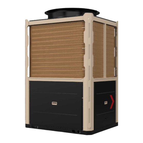
Page 8: Specification
Specification 1. Appearance and structure of the heat pump Water outlet Remote Controller (Manually) The longest distance of installing the Water inlet remote controller is 200 meters. 2. The data of unit *** REFRIGERANT : R290 Model PASRW S-BP-PS-D Heating Capacity(A) 13.63~50.00 Heating Power Input(A) 4.36~16.00... - Page 9 Part2: Test condition ; Part3:Test method ; Part4:related requirements.
- Page 10 户 川 出 怡...
-
Page 11: Installation
In sta l l a ti o n Unit features 1. Plate heat exchanger Use the SWEP efficient heat exchanger with small size and high efficiency. 2.Environmentally friendly refrigerant Use the new generation of environmentally friendly refrigerant R290, which is harmless to the ozone sphere. -
Page 12: Choose A Right Heat Pump Unit
In sta l l a ti o n 1.2 House Heating/Cooling(includes Buffer tank) 10 11 Buffer tank Check valve Heat pump Plate heat exchanger Floor heating valve Flexible pipe Buffer tank Floor heating pipe/fan coil unit Thermometer Expansion tank Manometer Relief valve Shut-off valve Air vent valve... -
Page 13: Installation Place
In sta l l a ti o n 4 Installation place The unit can be installed on any place outdoor which can carry heavy machine such as terrace, housetop, ground and so on. The location must have good ventilation. The place is free from heat radiation and other fire flame. A pall is needed in winter to protect the heat pump from snow. -
Page 14: Water Loop Connection
In sta l l a ti o n 6 Water loop connection Please pay attention to below matters when the water pipe is connected: Try to reduce the resistance to the water from the piping. The piping must be clear and free from dirty and blocks. Water leakage test must be carried out to ensure there is no water leaking. -
Page 15: Transit
In sta l l a ti o n Installation space for multiple units (same pipe length): (unit: mm) 1000 1000 1000 1000 1000 1000 1000 ≥1500 1000 Note: Do not cover the air outlet of the unit; If there is a barrier above the unit, please keep it 3000mm above the unit;... -
Page 16: Trial Running
In sta l l a ti o n When the unit need to be hung up during installation, a 8 meters cable is needed, and there must be soft material between the cable and the unit to prevent damage to the heat pump cabinet. - Page 17 In sta l l a ti o n by user himself.
-
Page 18: Operation And Use
Op e ra ti o n a n d U se 5.1. Main interface display and function (1) Electricity Interface Fig.1 Electricity interface (2) Main interface of power-off interface Fig.2 Power-off interface... - Page 19 Op e ra ti o n a n d U se (3) Main interface of power-on 13 14 15 16 17 18 19 ① ④ ② ⑤ ③ ⑥ Fig.3 Power-on interace ⑦ ⑧ ⑨ ⑩ Button function Name Function ①...
- Page 20 Op e ra ti o n a n d U se ⑧ Indicating the operating mode: Heating or Cooling...
-
Page 21: Instructions For Operation Of Wire Controller
Op e ra ti o n a n d U se Icon Description Indicating the operating status: ⑨ Display circle blue--cooling mode; red-heating mode; grey-power-off mode. ⑩ Indicating the target temperature of inlet water Indicating the date and time Indicating the ambient temperature Indicating the Temp Timer function is activated Indicating that the mute mode is activated Indicating that the defrost mode is activated... - Page 22 Op e ra ti o n a n d U se (5) Timer setting Fig. 4 Timer interface Button function Name Function Press to jump to the time-sharing temperature control setting Temp Timer interface Power Timer Press to jump to the timing switch setting interface Mute Timer Press to jump to the Mute Timer interface Temp Timer Fig.
- Page 23 Op e ra ti o n a n d U se Name Function Click whether to enable time-sharing temperature control in Enable key this section, the icon for opening is green and the icon for closing is grey. Mode setting Set the mode for the time-sharing temperature control Temperatur Set the target temperature for the time-sharing temperature e setting...
- Page 24 Op e ra ti o n a n d U se Mute Timer Fig. 7 Mute timer interface To enable Mute Timer function, firstly press Timer button ⑤ in the main inter- face, secondly press Mute Timer button 22 (Fig.4), it jumps to Mute Timer interface, enter the start and end timer, and lastly press on/off button to enable or disable the setting.
- Page 25 Op e ra ti o n a n d U se (6) Setting function Page right Fig. 9 Setting interface P age Page right left Fig. 10 Setting interface...
- Page 26 Op e ra ti o n a n d U se Page left Fig. 11 Setting interface Button function Name Function Press to jump to the status inquiry interface to inquire the Status running and unit status paramerter Press and enter password “22” to inquire installer parameter Parameter Failure Press to inquire failure record...
- Page 27 Op e ra ti o n a n d U se Setting interface In the main interface, press Setting button ⑥ to jump to Setting interface (Fig.9). Status inquiry function In the Setting interface (Fig.9), press Status button 33 to jump to Status interface. Fig.12 Status interface Running Status inquiry funtion In the Status interface, press Running Status button...
- Page 28 Op e ra ti o n a n d U se Failure record inquiry function While failure occurs, the icon is flashing in the main interface. In the Setting interface (Fig.9), press Failure button 35 to jump to Failure Record interface for inquiring the current failure records (Fig.14).
- Page 29 Op e ra ti o n a n d U se Fig.15-1 Delete history failure interface Fig.15-2 Recovery the failure three times to lock interface...
- Page 30 Op e ra ti o n a n d U se System time setting In the Setting interface (Fig.9), press Time button 36 to jump to Time Setting interface (Fig.16), click on the input field and enter time digital, press save the settings.
- Page 31 Op e ra ti o n a n d U se a) This curve function records the water inlet temperature,water outlet temperature and ambient temperature; b) Temperature data is collected every 5 minutes and the 12 sets of temperature data are saved every hour. Timekeeping is made from the latest data saving, if the power is disrupted when the time is less than 1 hour (12 sets), the data during such period will not be saved.
- Page 32 Op e ra ti o n a n d U se Fast Mute function In the Setting interface (Fig.10), while the botton 39 displays “OFF Fast Mute” and ”, press this button 39 to enable fast mute function and it displays “ON Fast “...
- Page 33 Op e ra ti o n a n d U se Fig. 20 Weather Compensation interface...
- Page 34 Op e ra ti o n a n d U se Note: When disable the Ambient Temp Compensation function, the targer temp display “----”. Pre-heating function In the Setting interface (Fig.11), while the botton displays “OFF Pre-heating” and “ ”, press this button to enable pre-heating function and it displays “ON Pre-heating”...
-
Page 35: Electronic Control Failure Code And Troubleshooting Table
Op e ra ti o n a n d U se 5.3 Electronic control failure code and troubleshooting table Failure code and troubleshooting table Protection/failure Codes Causes Removal methods Inspect whether the wire controller, the main Abnormal communication between wire Communication Fault board and the connection thereof are reliable controller and the main board... - Page 36 Op e ra ti o n a n d U se Protection/fault Codes Causes Removal methods Check and replace the system 1 coil 1 Syst1: Coil Temp Sensor1 Fault P150 The temperature sensor is open or short circuited temperature sensor AT Sensor Fault The temperature sensor is open or short circuited Check and replace the ambient temperature sensor Check and replace the system 1 return air...
- Page 37 Op e ra ti o n a n d U se Protection/fault Codes Causes Removal methods Syst1:The Inverter Board Bus Under F158 Voltage is too low Check if the input voltage is lower than 250V Voltage Prot. Syst2: The Inverter Board Communication failure with system 2 inverter 1.
- Page 38 Op e ra ti o n a n d U se Protection/fault Codes Causes Removal methods DC Fan Motor 1 F110 The fan speed of system 1 is incorrect Check if the system 1 fan rotor is locked Lowspeed Protection DC Fan Motor 2 F210 The fan speed of system 2 is incorrect...
- Page 39 OUT12 OUT11 OUT10 OUT9 OUT4 OUT3 OUT2 OUT1 OUT16 OUT15 OUT14 OUT13 OUT24 OUT23 OUT22 OUT21 OUT20 OUT19 OUT18 OUT17 OUT8 OUT7 OUT6 OUT5 JP12 JP11 JP10 CN300 J205 J203 J201 BP2000 J206 J204 J202 CN5-1 A61 CN6 CN7 A49 A35 A34 A33 A27 A26 A20 A19...
- Page 40 HEAD10 HEAD9 HEAD8 HEAD7 HEAD6 HEAD5 A45 A44 A43 A40 A39 A38 A37 A36 A32 A31 A30 A29 A28 A25 A24 A23 A22 A21 A18 A17 A14 A13 A12 A9 A8 A3 A2 A1 CN10 CN19 HEAD4 HEAD3 HEAD2 HEAD1...
- Page 41 (3) The input and output interface instructions No. Sign Meaning No. Sign Meaning Syst1: Antifreezing Temp Syst1: Fan Overload Prot. Syst1: Coil Temp 1 Syst2: Fan Overload Prot. Syst1: Coil Temp 2 Reserved Water Flow Switch Reserved Emergency Input Reserved Mode Reserved Electric Heater Overload...
- Page 42 Op e ra ti o n a n d U se No. Sign Meaning Sign Meaning CN23 Reserved OUT8 Reserved 82 CN300 Program port OUT9 Syst1:4-Way Valve OUT10 Syst2:4-Way Valve J201 Compressor inverter board 1 OUT11 Reserved J202 Compressor inverter board 2 OUT12 Reserved J203...
-
Page 43: Appendix (1) Appendix
Appendix 6. Appendix 1 、 Caution & Warning 1. The unit can only be repaired by qualified installer centre personnel or an authorised dealer.(for Europe market) 2. This appliance is not intended for use by persons (including children) with reduced physical sensory or mental capabilities, or lack of experience and knowledge, unless they have been given supervision or instruction concerning use of the appliance by a person responsible for their safety. - Page 44 Ap p e n d i x 6. Appendix 2 、 Cable specification 1. Single phase unit Nameplate Creepage protector Signal line maximum Phase line Earth line current No more 2×1.5mm 1.5mm 30mA less than 0.1 sec than 10A 2×2.5mm 2.5mm 30mA less than 0.1 sec 10~16A...
- Page 45 Note...
- Page 46 NORDIC REFRIGERATION SOLUTIONS APS Karetmagervej 19C 7100 Vejle Tel nr.: 38424848 E-mail: Info@nordicrefrigerationsolutions.com Website: www.nordicrefrigerationsolutions.com Code 2 0221130-0002...
Need help?
Do you have a question about the PASRW150S-BP-PS-D and is the answer not in the manual?
Questions and answers