NetApp E5700 Manual
Hide thumbs
Also See for E5700:
- Hardware maintainence manual (397 pages) ,
- Manual (133 pages) ,
- Manual (36 pages)

Subscribe to Our Youtube Channel
Related Manuals for NetApp E5700


Summary of Contents for NetApp E5700
- Page 1 E-Series Maintaining E5700 Hardware September 2018 | 215-13052_A0 doccomments@netapp.com...
-
Page 3: Table Of Contents
Table of Contents | 3 Contents Batteries ......................6 Overview and requirements ..................6 Battery overview ..................... 6 Requirements for replacing a failed battery ............ 6 Replace battery ......................7 Place controller offline (duplex) ..............7 Remove failed battery ..................9 Install new battery .................. - Page 4 4 | Maintaining E5700 Hardware Overview and requirements ..................51 Drives overview ..................... 51 Drive drawer overview .................. 52 Requirements for handling drives ..............53 Replace drive (24-drive) .................... 54 Prepare to replace drive (24-drive) ..............54 Remove failed drive (24-drive) ..............55 Install new drive (24-drive) ................
- Page 5 Table of Contents | 5 Stop host I/O ....................131 Change the feature pack ................132 Complete host protocol conversion ............. 133 Copyright information ................138 Trademark information ................139 How to send comments about documentation and receive update notifications ..................140...
-
Page 6: Batteries
Steps needed to replace battery The following is an overview of the steps to replace a battery in E5700 controllers (E5724, EF570, or E5760): 1. Take controller offline. -
Page 7: Replace Battery
Batteries | 7 Replace battery Each controller canister includes a battery that preserves cached data if the AC power fails. If the Recovery Guru in SANtricity System Manager reports either a Battery Failed status or a Battery Replacement Required status, you must replace the affected battery. Steps Place controller offline (duplex) on page 7... - Page 8 8 | Maintaining E5700 Hardware d. Type the following command in the text box. save storageArray dbmDatabase sourceLocation=onboard contentType=all file="filename"; In this command, is the file path and file name to which you want to save the filename database. Enclose the file name in double quotation marks (" "). For example: file="C:\Program Files\CLI\logs\dbmdata.zip"...
-
Page 9: Remove Failed Battery
Batteries | 9 The system attempts to take the controller offline. 6. Wait for System Manager to update the controller's status to offline. Do not begin any other operations until after the status has been updated. Attention: After you finish Remove failed battery Go to on page 9. - Page 10 10 | Maintaining E5700 Hardware Controller canister Cam handle The following figure is an example of an E5760 controller shelf: Controller canister Cam handle 7. Using two hands and the cam handle, slide the controller canister out of the shelf.
- Page 11 Batteries | 11 After you finish Step 2: Remove failed battery Go to on page 11. Step 2: Remove failed battery After removing the controller canister from the controller shelf, you can remove the battery. Steps 1. Remove the controller canister's cover by pressing down on the button and sliding the cover off. 2.
-
Page 12: Install New Battery
12 | Maintaining E5700 Hardware Battery release latch Battery 5. Lift up on the battery, and slide it out of the controller canister. 6. Follow the appropriate procedures for your location to recycle or dispose of the failed battery. Warning: To comply with International Air Transport Association (IATA) regulations, never ship a lithium battery by air unless it is installed within the controller shelf. - Page 13 Batteries | 13 Step 1: Install new battery Install a new battery when the old one has failed. Before you begin • You have the failed battery from the controller canister. • You have the replacement battery. Steps 1. Unpack the new battery, and set it on a flat, static-free surface. To comply with IATA safely regulations, replacement batteries are shipped with a Important: state of charge (SoC) of 30 percent or less.
- Page 14 14 | Maintaining E5700 Hardware • Correct – The battery's metal flange is completely inserted in the slot on the controller: • Incorrect – The battery's metal flange is not inserted into the slot on the controller: After you finish...
- Page 15 Batteries | 15 Controller canister Cam handle Controller canister Cam handle 4. Move the cam handle to the left to lock the controller canister in place. 5. Reconnect all the cables. After you finish Place controller offline (duplex) Go to on page 16.
-
Page 16: Place Controller Online (Duplex)
16 | Maintaining E5700 Hardware Place controller online (duplex) Place the controller online to confirm the storage array is working correctly. Then, you can collect support data and resume operations. About this task Perform this task only if your storage array has two controllers. - Page 17 Batteries | 17 c. Select Tools > Execute Script. d. Type one of the following commands in the text box. For controller A: set controller [a] availability=online; For controller B: set controller [b] availability=online; e. Select Tools > Verify and Execute. The system places the controller online.
-
Page 18: Controllers
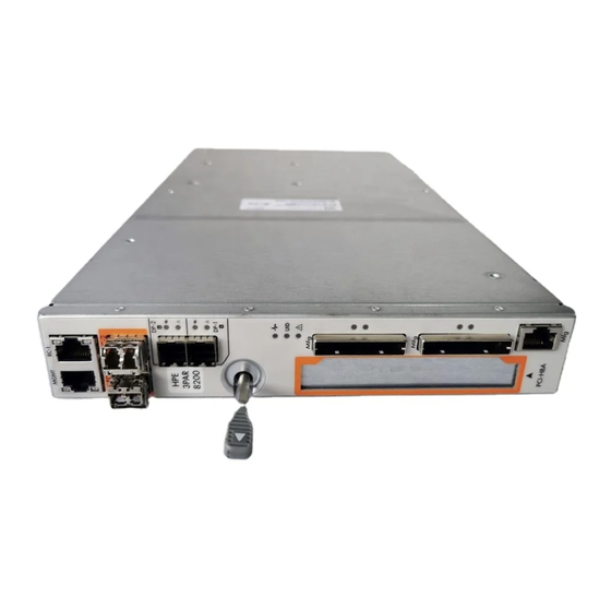
Controllers A controller consists of a board, firmware, and software. It controls the drives and implements the System Manager functions. This section describes how to replace a controller in a duplex configuration. Overview and requirements This topic provides an overview of the controller and describes the requirements you need to know about before replacing a controller or adding a second controller. -
Page 19: Requirements For Replacing A Controller
Controllers | 19 Requirements for replacing a controller If you plan to replace a controller or add a second controller, keep the following requirements in mind. Requirements for replacing a failed controller • You must have a replacement controller canister with the same part number as the controller canister you are replacing. -
Page 20: Prepare To Replace Controller (Duplex)
20 | Maintaining E5700 Hardware Related concepts Controller overview on page 18 Requirements for replacing a controller on page 19 Prepare to replace controller (duplex) You prepare to replace a controller canister by verifying that the replacement controller canister has the correct FRU part number, backing up the configuration, and collecting support data. - Page 21 Controllers | 21 a. Select Hardware. b. Locate the controller shelf, which is marked with the controller icon c. Click the controller icon. d. Select the controller, and click Next. e. On the Base tab, make a note of the Replacement Part Number for the controller. 4.
-
Page 22: Remove Failed Controller (Duplex)
22 | Maintaining E5700 Hardware b. If the graphic shows the drives, select Show back of shelf to show the controllers. c. Select the controller that you want to place offline. d. From the context menu, select Place offline, and confirm that you want to perform the operation. - Page 23 Controllers | 23 Step 1: Remove controller canister (duplex) You remove the failed controller canister so you can replace it with a new one. Before you begin • You must use labels to identify each cable that is connected to the controller canister. •...
- Page 24 24 | Maintaining E5700 Hardware Controller canister Cam handle 7. Using two hands and the cam handle, slide the controller canister out of the shelf. Always use two hands to support the weight of a controller canister. Attention: If you are removing the controller canister from an E5724 controller shelf, a flap swings into place to block the empty bay, helping to maintain air flow and cooling.
- Page 25 Controllers | 25 Internal Cache Active LED Battery 3. Locate the blue release latch for the battery. 4. Unlatch the battery by pushing the release latch down and away from the controller canister. Battery release latch Battery 5. Lift up on the battery, and slide it out of the controller canister.
- Page 26 26 | Maintaining E5700 Hardware After you finish Step 3: Remove host interface card (duplex) Go to on page 26. Step 3: Remove host interface card (duplex) If the controller canister includes a host interface card (HIC), you must remove the HIC from the original controller canister, so you can reuse it in the new controller canister.
-
Page 27: Install New Controller (Duplex)
Controllers | 27 Host interface card (HIC) Thumbscrews 5. Place the HIC on a static-free surface. After you finish Go to Install new controller (duplex) on page 27. Install new controller (duplex) You install a new controller canister to replace the failed one. Perform this task only if your storage array has two controllers (duplex configuration). - Page 28 28 | Maintaining E5700 Hardware Steps 1. Turn the replacement controller canister over, so that the removable cover faces up. 2. Press down on the cover button, and slide the cover off. 3. Orient the controller canister so that the slot for the battery faces toward you.
- Page 29 Controllers | 29 • Incorrect – The battery's metal flange is not inserted into the slot on the controller: After you finish Step 3: Remove host interface card (duplex) Go to on page 26. Step 2: Install host interface card (duplex) If you removed a HIC from the original controller canister, you must install that HIC in the new controller canister.
- Page 30 30 | Maintaining E5700 Hardware Host interface card (HIC) Thumbscrews 4. Hand-tighten the HIC thumbscrews. Do not use a screwdriver, or you might over tighten the screws. 5. Using a #1 Phillips screwdriver, attach the HIC faceplate you removed from the original controller canister to the new controller canister with four screws.
- Page 31 Controllers | 31 Step 3: Install new controller canister (duplex) After installing the battery and the host interface card (HIC), if one was initially installed, you can install the new controller canister into the controller shelf. Steps 1. Reinstall the cover on the controller canister by sliding the cover from back to front until the button clicks.
-
Page 32: Complete Controller Replacement (Duplex)
32 | Maintaining E5700 Hardware Controller canister Cam handle 4. Move the cam handle to the left to lock the controller canister in place. 5. Install the SFPs from the original controller in the host ports on the new controller, and reconnect all the cables. - Page 33 Controllers | 33 Possible loss of data access – If the controller you just installed shows one these Attention: codes, and the other controller is reset for any reason, the second controller also could lock down. 3. When the controller is back online, confirm that its status is Optimal and check the controller shelf’s Attention LEDs.
-
Page 34: Canisters
Controller shelf with two power supplies (power-fan canisters) below the controller canisters. Replace power supply topics do not describe how to replace a failed power-fan canister in a DE1600 or DE5600 drive tray, which might be connected to the E5700 or E2800 controller shelves. Replacing a Power-Fan Canister in the DE1600... -
Page 35: Fan Canister Overview
Canisters | 35 • E5760 controller shelves • DE460C drive shelf Replace power canister topics do not describe how to replace a failed power canister in a DE6600 drive tray, which might be connected to the controller shelf. The following figure shows the back of a DE460C drive shelf with the two power canisters: The following figure shows a power canister: Fan canister overview Each 60-drive controller shelf or drive shelf includes two fan canisters. -
Page 36: Requirements For Replacing A Power Supply
36 | Maintaining E5700 Hardware The following figure shows the back of a DE460C shelf with two fan canisters: Possible equipment damage — If you replace a fan canister with the power turned on, Attention: you must complete the replacement procedure within 30 minutes to prevent the possibility of overheating the equipment. -
Page 37: Requirements For Replacing A Power Canister
Canisters | 37 Requirements for replacing a power canister If you plan to replace a power canister, keep the following requirements in mind. • You have a replacement power canister that is supported for your controller shelf or drive shelf model. -
Page 38: Prepare To Replace Power Supply
38 | Maintaining E5700 Hardware Steps Prepare to replace power supply on page 38 You prepare to replace a power supply in a 24-drive controller shelf or drive shelf by collecting support data about your storage array and locating the failed component. The power supply is referred to as a power-fan canister in SANtricity System Manager. - Page 39 Canisters | 39 c. Click Collect. The file is saved in the Downloads folder for your browser with the name support-data.7z 2. From SANtricity System Manager, determine which power supply has failed. You can find this information in the Details area of the Recovery Guru, or you can review the information displayed for the shelf.
-
Page 40: Remove Failed Power Supply
40 | Maintaining E5700 Hardware Remove failed power supply You remove a failed power supply so you can replace it with a new one. When you remove a power supply (referred to in SANtricity System Manager as a power-fan canister ), you turn off power, disconnect the power cord, and slide the part out of the shelf. -
Page 41: Install New Power Supply
Canisters | 41 4. Use the cam handle to slide the power supply out of the system. When removing a power supply, always use two hands to support its weight. Attention: As you remove the power supply, a flap swings into place to block the empty bay, helping to maintain air flow and cooling. -
Page 42: Replace Power Canister (60-Drive)
The file is saved in the Downloads folder for your browser with the name support-data.7z 6. Return the failed part to NetApp, as described in the RMA instructions shipped with the kit. Result Your power supply replacement is complete. You can resume normal operations. -
Page 43: Prepare To Replace Power Canister
Canisters | 43 Prepare to replace power canister You prepare to replace a power canister in a 60-drive controller shelf or drive shelf by collecting support data about your storage array and locating the failed component. Before you begin • You have reviewed the details in the Recovery Guru to confirm that there is an issue with a battery and to ensure no other items must be addressed first. -
Page 44: Remove Failed Power Canister
44 | Maintaining E5700 Hardware You can also find information about the failed power canister in the Details area of the Note: Recovery Guru, or you can review the information displayed for the shelf, or you can review the Event Log under Support and filter by Component Type. -
Page 45: Install New Power Canister
Canisters | 45 5. Press the orange latch on the power canister cam handle, and then open the cam handle to fully release the power canister from the mid plane. 6. Use the cam handle to slide the power canister out of the shelf. When removing a power canister, always use two hands to support its weight. -
Page 46: Replace Fan Canister (60-Drive)
The file is saved in the Downloads folder for your browser with the name support-data.7z 6. Return the failed part to NetApp, as described in the RMA instructions shipped with the kit. Result Your power canister replacement is complete. You can resume normal operations. - Page 47 Canisters | 47 • DE460C drive shelf Possible equipment damage — If you perform this procedure with the power turned on, Attention: you must complete it within 30 minutes to prevent the possibility of overheating the equipment. Steps 1. Collect support data for your storage array using SANtricity System Manager. a.
-
Page 48: Remove Failed Fan Canister And Install New One
48 | Maintaining E5700 Hardware Attention LED. If this LED displays as Solid amber, then the fan has a fault. After you finish Remove failed power canister and install new one Go to on page 48. Remove failed fan canister and install new one You remove a failed fan canister so you can replace it with a new one. - Page 49 Canisters | 49 Tab that you press to release the fan canister handle. 3. Use the fan canister handle to pull the fan canister out of the shelf. Handle to pull the fan canister out. 4. Slide the replacement fan canister all the way into the shelf, and then move the fan canister handle until it latches with the orange tab.
-
Page 50: Complete Fan Canister Replacement
The file is saved in the Downloads folder for your browser with the name support-data.7z 6. Return the failed part to NetApp, as described in the RMA instructions shipped with the kit. Result Your fan canister replacement is complete. You can resume normal operations. -
Page 51: Drives
Drives A drive is an electromagnetic mechanical device that provides the physical storage media for data. Overview and requirements Before you replace a drive, you need to be aware of certain requirements and considerations. Drives overview You can replace a drive in either a 24-drive or 60-drive controller shelf or drive shelf. 24-drive shelves The figures show how the drives are numbered in each type of shelf (the shelf's front bezel or end caps have been removed). -
Page 52: Drive Drawer Overview
52 | Maintaining E5700 Hardware For both an E5760 controller shelf drawer and a DE460C drive shelf drawer, drives are numbered from 0 to 11 in each drive drawer within the shelf. Your E5760 storage array might include one or more SAS-2 legacy expansion drive trays, Note: including the DE1600 12-drive tray, the DE5600 24-drive tray, or the DE6600 60-drive tray. -
Page 53: Requirements For Handling Drives
Drives | 53 Requirements for handling drives The drives in your storage array are fragile. Improper drive handling is a leading cause of drive failure. Follow these rules to avoid damaging the drives in your storage array: • Prevent electrostatic discharge (ESD): ◦... -
Page 54: Replace Drive (24-Drive)
54 | Maintaining E5700 Hardware Replace drive (24-drive) The Recovery Guru in SANtricity System Manager monitors the drives in the storage array and can notify you of an impending drive failure or an actual drive failure. When a drive has failed, its amber Attention LED is on. -
Page 55: Remove Failed Drive (24-Drive)
Drives | 55 After you finish Remove failed drive (24-drive) Go to on page 55. Remove failed drive (24-drive) You remove a failed drive to replace it with a new one. Before you begin • You have an ESD wristband, or you have taken other antistatic precautions. Requirements for handling drives •... -
Page 56: Install New Drive (24-Drive)
Otherwise, there is a risk that the equipment might overheat. Before you begin • You have a replacement drive that is supported by NetApp for your controller shelf or drive shelf. Steps 1. Open the cam handle. -
Page 57: Replace Drive (60-Drive)
When the drive reconstruction completes, the volume group is in an Optimal state. 4. As required, reinstall the bezel. 5. Return the failed part to NetApp, as described in the RMA instructions shipped with the kit. Result Your drive replacement is complete. You can resume normal operations. - Page 58 58 | Maintaining E5700 Hardware c. Click the drive to display its context menu, and then select View settings. d. Confirm that the replacement drive has a capacity equal to or greater than the drive you are replacing and that it has the features you expect.
- Page 59 Drives | 59 Attention LED light on for the drive on the top right side The drive drawer Attention LEDs are on the left side in front of each drive, with an attention icon on the drive handle just behind the LED. Attention icon Attention LED After you finish...
-
Page 60: Remove Failed Drive (60-Drive)
60 | Maintaining E5700 Hardware Remove failed drive (60-drive) You remove a failed drive to replace it with a new one. Before you begin • You have an ESD wristband, or you have taken other antistatic precautions. • You have reviewed the Requirements for handling drives on page 53 topic. -
Page 61: Install New Drive (60-Drive)
Otherwise, there is a risk that the equipment might overheat. Before you begin • You have a replacement drive that is supported by NetApp for your controller shelf or drive shelf. About this task Possible loss of data access – When pushing the drive drawer back into the enclosure, Attention: never slam the drawer shut. -
Page 62: Complete Drive Replacement (60-Drive)
62 | Maintaining E5700 Hardware Raised button on the right side of the drive carrier 3. Lower the drive straight down, and then rotate the cam handle down until the drive snaps into place under the orange release latch. 4. Carefully push the drive drawer back into the enclosure. Push the drawer in slowly to avoid jarring the drawer and causing damage to the storage array. -
Page 63: Replace Drive Drawer (60-Drive)
When the drive reconstruction completes, the volume group is in an Optimal state. 4. As required, reinstall the bezel. 5. Return the failed part to NetApp, as described in the RMA instructions shipped with the kit. Result Your drive replacement is complete. You can resume normal operations. -
Page 64: Prepare To Replace Drive Drawer (60-Drive)
64 | Maintaining E5700 Hardware Complete drive drawer replacement (60-drive) on page 77 You complete the drive drawer replacement by reinserting the drives and replacing the front bezel in the correct order. Related concepts Drive drawer overview on page 52... - Page 65 Drives | 65 • ] is the identifier of the drive drawer that you want to replace. Drawer ID values drawerID are 1 (top drawer) to 5 (bottom drawer). You must enclose the value for in square drawerID brackets. Example This command ensures you can remove the top-most drawer in drive shelf 10: SMcli <ctlr_IP1>...
-
Page 66: Remove Cable Chains
66 | Maintaining E5700 Hardware Cache Active LED 7. From the Home page of SANtricity System Manager, select View Operations in Progress. 8. Wait for all operations to complete before continuing with the next step. 9. Power off the shelves as follows: If you are replacing a drawer in a shelf with Drawer Loss Protection: There is NO need to power off any of the shelves. - Page 67 Drives | 67 About this task Each drive drawer has left and right cable chains. The metal ends on the cable chains slide into corresponding vertical and horizontal guide rails inside the enclosure, as follows: • The left and right vertical guide rails connect the cable chain to the enclosure's midplane. •...
- Page 68 68 | Maintaining E5700 Hardware The top cable chain is attached to drive drawer 1. The bottom cable chain is attached to drive drawer 5. The callouts for drive drawer 1 are provided. Cable chain Vertical connector (connected to midplane)
- Page 69 Drives | 69 Orange ring on vertical guide rail Cable chain, partially removed b. To unlatch the cable chain, insert your finger into the orange ring and press towards the middle of the system. c. To unplug the cable chain, carefully pull your finger toward you approximately 1 inch (2.5 cm).
- Page 70 70 | Maintaining E5700 Hardware Orange ring on horizontal guide rail Cable chain, partially removed b. To unlatch the cable chain, gently insert your finger into the orange ring and push down. The figure shows the orange ring on the horizontal guide rail (see item 1 in the figure above), as it is pushed down so that the rest of the cable chain can be pulled out of the enclosure.
-
Page 71: Remove Failed Drive Drawer (60-Drive)
Drives | 71 Possible equipment damage due to overheating – If the shelf is powered on, do Attention: not remove both fans at the same time. Otherwise, the equipment might overheat. 10. Disconnect the left cable chain from its vertical guide rail: a. - Page 72 72 | Maintaining E5700 Hardware 3. Using the extended levers, carefully pull the drive drawer out until it stops. Do not completely remove the drive drawer from the drive shelf. 4. If volumes have already been created and assigned, use a permanent marker to note the exact location of each drive.
-
Page 73: Install New Drive Drawer (60-Drive)
Drives | 73 Drive drawer release lever b. Disengage both release levers by pulling the latches toward you. c. While holding both release levers, pull the drive drawer toward you. d. Remove the drive drawer from the drive shelf. After you finish Install new drive drawer (60-drive) Go to on page 73. -
Page 74: Attach Cable Chains
74 | Maintaining E5700 Hardware Lock-out tumbler Drawer guide 2. Position the replacement drive drawer in front of the empty slot and slightly to the right of center. Positioning the drawer slightly to the right of center helps to ensure that the lock-out tumbler and the drawer guide are correctly engaged. - Page 75 Drives | 75 About this task When attaching a cable chain, reverse the order you used when disconnecting the cable chain. You must insert the chain's horizontal connector into the horizontal guide rail in the enclosure before inserting the chain's vertical connector into the vertical guide rail in the enclosure. Steps 1.
- Page 76 76 | Maintaining E5700 Hardware Horizontal guide rail Vertical guide rail d. Slide the vertical connector on the right cable chain into the vertical guide rail. e. After you have reconnected both ends of the cable chain, carefully pull on the cable chain to verify that both connectors are latched.
-
Page 77: Complete Drive Drawer Replacement (60-Drive)
Drives | 77 7. Reattach the left cable chain: a. Locate the horizontal and vertical connectors on the cable chain and their corresponding horizontal and vertical guide rails inside the enclosure. b. Align both cable chain connectors with their corresponding guide rails. c. - Page 78 78 | Maintaining E5700 Hardware d. Raise the handle on the drive to vertical. e. Align the two raised buttons on each side of the drive with the notches on the drawer. The figure shows the right-side view of a drive, showing the location of the raised buttons.
- Page 79 Drives | 79 g. Repeat these steps to install all the drives. 2. Slide the drawer back into the drive shelf by pushing it from the center and closing both levers. Risk of equipment malfunction – Make sure to completely close the drive drawer Attention: by pushing both levers.
-
Page 80: Host Interface Cards
Host interface card overview You can add, upgrade, or replace a HIC in the E5724 controller shelf and the E5760 controller shelf: The E5700 controller has two SFP+ (optical) baseboard ports and you can install the following HICs: ◦ •... - Page 81 HIC ports. Upgrade HIC You change the host protocol by upgrading the HIC currently installed in an E5700 controller canister with a different type of HIC. The following figures show an E5724 controller shelf before and after a HIC upgrade.
- Page 82 HIC ports. Replace HIC When you replace a failed host interface card (HIC) in an E5700 controller shelf, you must remove the controller canister, replace the HIC, and reinstall the controller canister. The following figure...
-
Page 83: Requirements For Adding, Upgrading Or Replacing A Hic
Note: shelf. You might have different types and numbers of baseboard ports and HIC ports. The following is an overview of the steps to replace a HIC in an E5700 controllers (E5724 or E5760): 1. Take the controller offline 2. Remove the controller canister 3. -
Page 84: Add Host Interface Cards
You add host interface cards (HICs) to increase the number of host ports in your storage array and to provide additional host protocols. When you add HICs, you must power off the storage array, install the HIC, and reapply power. You can add HICs to E5700 controller canisters that only have baseboard host ports. - Page 85 Host interface cards | 85 b. Select the storage array. c. Select Tools > Execute Script. d. Type the following command in the text box. save storageArray dbmDatabase sourceLocation=onboard contentType=all file="filename"; In this command, is the file path and file name to which you want to save the filename database.
-
Page 86: Add Host Interface Card
86 | Maintaining E5700 Hardware Cache Active LED 7. From the Home page of SANtricity System Manager, select View Operations in Progress. Wait for all operations to complete before continuing with the next step. 8. Power down the controller shelf. - Page 87 Host interface cards | 87 To prevent degraded performance, do not twist, fold, pinch, or step on the cables. Attention: 3. Confirm that the Cache Active LED on the back of the controller is off. The green Cache Active LED on the back of the controller is on when cached data needs to be written to the drives.
- Page 88 The HICs must be compatible with your controllers. About this task Possible loss of data access – Never install a HIC in an E5700 controller canister if Attention: that HIC was designed for another E-Series controller. In addition, if you have a duplex configuration, both controllers and both HICs must be identical.
- Page 89 Host interface cards | 89 Steps 1. Unpack the new HIC and the new HIC faceplate. 2. Press the button on the cover of the controller canister, and slide the cover off. 3. Confirm that the green LED inside the controller (by the DIMMs) is off. If this green LED is on, the controller is still using battery power.
- Page 90 90 | Maintaining E5700 Hardware Host interface card (HIC) Thumbscrews 7. Hand-tighten the HIC thumbscrews. Do not use a screwdriver, or you might over tighten the screws. 8. Using a #1 Phillips screwdriver, attach the new HIC faceplate to the controller canister with the...
- Page 91 Host interface cards | 91 After you finish Step 3: Reinstall controller canister Go to on page 91. Step 3: Reinstall controller canister You reinstall the controller canister into the controller shelf after installing the new HIC. Steps 1. Turn the controller canister over, so that the removable cover faces down. 2.
-
Page 92: Complete Adding A Host Interface Card
92 | Maintaining E5700 Hardware Controller canister Cam handle 3. Move the cam handle to the left to lock the controller canister in place. 4. Reconnect all the cables you removed. Attention: Do not connect data cables to the new HIC ports at this time. - Page 93 Host interface cards | 93 Steps 1. Turn on the two power switches at the back of the controller shelf. • Do not turn off the power switches during the power-on process, which typically takes 90 seconds or less to complete. •...
-
Page 94: Upgrade Host Interface Card
If the new HIC ports do not have the protocol you expect: You must apply a software feature pack before you can connect the new HIC ports to the data Converting the Protocol of E5700 Host Ports . Then, use the instructions in that hosts. See document to connect the host ports to the data hosts and to resume operations. -
Page 95: Prepare To Upgrade Host Interface Cards
Host interface cards | 95 Prepare to upgrade host interface cards You prepare to upgrade host interface cards (HICs) by backing up the storage array's configuration database, collecting support data, and stopping host I/O operations. Then, you can power down the controller shelf. -
Page 96: Upgrade Host Interface Card
96 | Maintaining E5700 Hardware 4. Ensure that no I/O operations are occurring between the storage array and all connected hosts. For example, you can perform these steps: • Stop all processes that involve the LUNs mapped from the storage to the hosts. - Page 97 Host interface cards | 97 Remove the controller canister so you can upgrade the new host interface card. When you remove a controller canister, you must disconnect all cables. Then, you can slide the controller canister out of the controller shelf. Step 2: Remove a host interface card on page 99 Remove the original host interface card so you can replace it with an upgraded one.
- Page 98 98 | Maintaining E5700 Hardware Controller canister Cam handle The following figure is an example of an E5760 controller shelf: Controller canister Cam handle 6. Using two hands and the cam handle, slide the controller canister out of the shelf.
- Page 99 Host interface cards | 99 After you finish Step 2: Remove a host interface card Go to on page 99. Step 2: Remove a host interface card You remove the original host interface card (HIC) so you can replace it with an upgraded one. Before you begin •...
- Page 100 100 | Maintaining E5700 Hardware 4. Remove the HIC faceplate. 5. Using your fingers or a Phillips screwdriver, loosen the three thumbscrews that secure the HIC to the controller card. 6. Carefully detach the HIC from the controller card by lifting the card up and sliding it back.
- Page 101 About this task Attention: Possible loss of data access – Never install a HIC in an E5700 controller canister if that HIC was designed for another E-Series controller. In addition, if you have a duplex configuration, both controllers and both HICs must be identical. The presence of incompatible or mismatched HICs will cause the controllers to lock down when you apply power.
- Page 102 102 | Maintaining E5700 Hardware 3. Align the three thumbscrews on the HIC with the corresponding holes on the controller, and align the connector on the bottom of the HIC with the HIC interface connector on the controller card. Be careful not to scratch or bump the components on the bottom of the HIC or on the top of the controller card.
- Page 103 Host interface cards | 103 2. Turn the controller canister over, so that the removable cover faces down. 3. With the cam handle in the open position, slide the controller canister all the way into the controller shelf. The following figure is an example of an E5724 controller shelf: Controller canister Cam handle The following figure is an example of an E5760 controller shelf:...
-
Page 104: Complete Upgrading A Host Interface Card Upgrade
104 | Maintaining E5700 Hardware 5. Reconnect all the cables you removed. Do not connect data cables to the new HIC ports at this time. Attention: 6. (Optional) If you are upgrading HICs in a duplex configuration, repeat all steps to remove the other controller canister, remove the HIC, install the new HIC, and replace the second controller canister. -
Page 105: Replace Host Interface Card
Host interface cards | 105 Host Link LEDs Attention LED (amber) Seven-segment display 3. From SANtricity System Manager, confirm that the controller's status is Optimal. If the status is not Optimal or if any of the Attention LEDs are on, confirm that all cables are correctly seated, and check that the HIC and the controller canister are installed correctly. -
Page 106: Place Controller Offline (Duplex)
106 | Maintaining E5700 Hardware Place controller offline (duplex) If you have a duplex configuration, you must place the affected controller offline so you can safely remove the failed HIC. You must back up the configuration and collect support data first. Then, you can take the affected controller offline. -
Page 107: Replace Host Interface Card
Host interface cards | 107 The file is saved in the Downloads folder for your browser with the name support-data.7z 4. If the controller is not already offline, take it offline now using either SANtricity System Manager or the Enterprise Management Window's (EMW) script editor: •... - Page 108 108 | Maintaining E5700 Hardware Step 2: Install host interface card on page 110 You install a host interface card (HIC) to replace the failed one with a new HIC. Step 3: Reinstall controller canister on page 112 After installing the host interface card (HIC), you reinstall the controller canister into the controller shelf.
- Page 109 Host interface cards | 109 Controller canister Cam handle The following figure is an example of an E5760 controller shelf: Controller canister Cam handle 5. Using two hands and the cam handle, slide the controller canister out of the shelf. Always use two hands to support the weight of a controller canister.
- Page 110 The HICs must be compatible with your controllers. About this task Possible loss of data access – Never install a HIC in an E5700 controller canister if Attention: that HIC was designed for another E-Series controller. In addition, if you have a duplex configuration, both controllers and both HICs must be identical.
- Page 111 Host interface cards | 111 5. Align the three thumbscrews on the HIC with the corresponding holes on the controller, and align the connector on the bottom of the HIC with the HIC interface connector on the controller card. Be careful not to scratch or bump the components on the bottom of the HIC or on the top of the controller card.
- Page 112 112 | Maintaining E5700 Hardware After you finish Step 3: Reinstall controller canister Go to on page 112. Step 3: Reinstall controller canister After installing the host interface card (HIC), you reinstall the controller canister into the controller shelf. Steps 1.
- Page 113 Host interface cards | 113 Controller canister Cam handle The following figure is an example of an E5760 controller shelf: Controller canister Cam handle 3. Move the cam handle to the left to lock the controller canister in place. 4. Reconnect all the cables you removed. Do not connect data cables to the new HIC ports at this time.
-
Page 114: Place Controller Online (Duplex)
114 | Maintaining E5700 Hardware After you finish Place controller online (duplex) Go to on page 114. Place controller online (duplex) You bring the controller online to confirm the storage array is working correctly. Then, you can collect support data and resume operations. - Page 115 Click Collect. The file is saved in the Downloads folder for your browser with the name support-data.7z 6. Return the failed part to NetApp, as described in the RMA instructions shipped with the kit. Contact technical support at NetApp Support , 888-463-8277 (North America), 00-800-44-638277 (Europe), or +800-800-80-800 (Asia/Pacific) if you need the RMA number.
-
Page 116: Host Port Protocol
Learn about the E5700 baseboard host ports and the requirements you need to know about before converting the host protocol. Host protocol overview You can convert the host port protocol of the baseboard host ports in the E5700 controller shelf. The following figure shows the E5700 with its SFP+ (optical) baseboard host ports and the optional two IB HIC ports. -
Page 117: Considerations For Changing The Host Protocol
If your configuration contains SAN Boot hosts connected to the FC baseboard ports, Note: check the NetApp Interoperability Matrix Tool to ensure that the configuration is supported on iSCSI. If it is not, you cannot convert the host protocol to iSCSI. •... -
Page 118: Change Host Protocol
118 | Maintaining E5700 Hardware volumes. Refer to the online help for SANtricity System Manager to change the settings for a volume to permanently disable the data assurance setting. After it has been disabled, DA cannot be re-enabled on the volume. - Page 119 Host port protocol | 119 Steps 1. From SANtricity System Manager, select Support. 2. Select the Support Center tile. 3. On the Support Resources tab, locate and select the Storage Array Profile link. 4. Type SFP in the text box, and click Find. 5.
-
Page 120: Obtain The Feature Pack
120 | Maintaining E5700 Hardware Obtain the feature pack To obtain the feature pack, you need the serial number from the controller shelf, a Feature Activation Code, and the Feature Enable Identifier for the storage array. Steps 1. Locate the serial number. - Page 121 Host port protocol | 121 3. Using the feature pack submodel ID, locate the corresponding Controller submodel ID for the starting configuration and find the Feature Activation Code for the desired ending configuration within the table below. Then, copy that Feature Activation Code to a text file. HIC Ports column in the following If you are not using the IB HIC, you can ignore the Note:...
- Page 122 122 | Maintaining E5700 Hardware Table 2: Encryption Capable Feature Activation Codes Starting configuration Ending configuration Feature Activation Code Control Basebo Control Basebo ports ports submod ports submod ports el ID el ID iSER UGG-XSB-ZCZKU iSCSI iSER SGL-2SB-ZEX13 iSCSI VGN-LTB-ZGFCT...
- Page 123 Host port protocol | 123 Starting configuration Ending configuration Feature Activation Code Control Basebo Control Basebo ports ports submod ports submod ports el ID el ID iSCSI iSER iSER 5GI-4TB-ZW3HL EGL-NTB-ZXKQ4 iSCSI HGP-QUB-Z1ICJ NVMe BGN-7UB-ZY1YY over InfiniBa iSCSI NVMe BGS-AUB-Z2YNG over InfiniBa NVMe...
- Page 124 124 | Maintaining E5700 Hardware Starting configuration Ending configuration Feature Activation Code Control Basebo Control Basebo ports ports submod ports submod ports el ID el ID NVMe iSER 3GN-TVB-ZINKM over 4GK-AUB-ZG69H InfiniBa iSCSI iSER BGP-DVB-ZJ4YC iSCSI BGU-GVB-ZM3KW iSCSI NVMe 4GX-ZVB-ZNJVD...
- Page 125 Host port protocol | 125 Starting configuration Ending configuration Feature Activation Code Control Basebo Control Basebo ports ports submod ports submod ports el ID el ID NVMe iSER BGC-UIK-Z03GR over LGF-EIK-ZPJRX RoCE iSCSI iSER PGJ-HIK-ZSIDZ iSCSI 1GM-1JK-ZTYQX NVMe JGH-XIK-ZQ142 over InfiniBa iSCSI NVMe...
- Page 126 126 | Maintaining E5700 Hardware Table 3: Non-Encryption Feature Activation Codes (Baseboard Port Only Conversions) Starting Ending Feature Activation Code configuration Configuration Controlle Ports to Controll Ports Convert Converte submode Submod d To l ID el ID iSCSI 9GU-2WB-Z503D baseboard...
- Page 127 Host port protocol | 127 Starting configuration Ending configuration Feature Activation Code Control Basebo Control Basebo ports ports submod ports submod ports el ID el ID iSER YG0-LXB-ZLD26 iSCSI iSER SGR-5XB-ZNTFB iSCSI PGZ-5WB-Z8M0N NVMe DGW-LWB-Z76KE over InfiniBa iSCSI NVMe KG2-0WB-Z9477 over InfiniBa NVMe...
- Page 128 128 | Maintaining E5700 Hardware Starting configuration Ending configuration Feature Activation Code Control Basebo Control Basebo ports ports submod ports submod ports el ID el ID iSCSI iSER LG8-JUB-ZATLD LGA-3UB-ZBAX1 iSCSI NGF-7UB-ZE8KX NVMe 3GI-QUB-ZFP1Y iSCSI NVMe 8GD-NUB-ZDRCD over InfiniBa NVMe...
- Page 129 Host port protocol | 129 Starting configuration Ending configuration Feature Activation Code Control Basebo Control Basebo ports ports submod ports submod ports el ID el ID iSCSI NVMe iSER GG5-8WB-ZBKEM over KG7-RWB-ZC2RZ InfiniBa iSCSI iSER NGC-VWB-ZFZEN iSCSI 4GE-FWB-ZGGQJ NVMe 1G9-CWB-ZDIZR over InfiniBa NVMe...
- Page 130 130 | Maintaining E5700 Hardware Starting configuration Ending configuration Feature Activation Code Control Basebo Control Basebo ports ports submod ports submod ports el ID el ID iSCSI NVMe iSER 6G0-SLK-ZW098 over CGQ-CLK-ZY5FS RoCE iSCSI iSER NGV-FLK-Z132Q iSCSI RGY-YLK-Z3KLD NVMe 5GT-VLK-ZZMPZ...
-
Page 131: Stop Host I/O
Host port protocol | 131 5. Go to NetApp License Activation: Storage Array Premium Feature Activation , and enter the information required to obtain the feature pack. • Chassis serial number • Feature Activation Code • Feature Enable Identifier Important: The Premium Feature Activation web site includes a link to “Premium Feature... -
Page 132: Change The Feature Pack
132 | Maintaining E5700 Hardware 4. From the Home page of SANtricity System Manager, select View Operations in Progress. 5. Wait for all operations to complete before continuing with the next step. After you finish Change the feature pack Go to on page 132. -
Page 133: Complete Host Protocol Conversion
Host port protocol | 133 b. Click Show back of shelf. c. Select the graphic for either Controller A or Controller B. d. Select View settings from the context menu. e. Select the Host Interfaces tab. f. Click Show more settings. g. - Page 134 134 | Maintaining E5700 Hardware You should configure the switches used to transport iSCSI traffic according to the vendor’s recommendations for iSCSI. These recommendations might include both configuration directives as well as code updates. 2. From SANtricity System Manager, select Hardware > Configure iSCSI ports.
- Page 135 Host port protocol | 135 g. Repeat these steps to add and remove any additional host port identifiers. 5. Reboot the host or perform a rescan so that the host properly discovers the LUNs. 6. Remount volumes or start using block volume. After you finish Your host protocol conversion is complete.
- Page 136 136 | Maintaining E5700 Hardware d. Click Add, and use the Add Host Port dialog box to associate a new host port identifier to the host. The length of the host port identifier name is determined by the host interface technology. FC host port identifier names must have 16 characters.
- Page 137 2. To connect the host to the storage array for an SRP configuration, you must enable the InfiniBand driver stack with the appropriate options. Specific settings might vary between Linux distributions. Check the NetApp Interoperability Matrix for specific instructions and additional recommended settings for your solution.
-
Page 138: Copyright Information
NetApp assumes no responsibility or liability arising from the use of products described herein, except as expressly agreed to in writing by NetApp. The use or purchase of this product does not convey a license under any patent rights, trademark rights, or any other intellectual property rights of NetApp. -
Page 139: Trademark Information
Trademark information NETAPP, the NETAPP logo, and the marks listed on the NetApp Trademarks page are trademarks of NetApp, Inc. Other company and product names may be trademarks of their respective owners. http://www.netapp.com/us/legal/netapptmlist.aspx... -
Page 140: How To Send Comments About Documentation And Receive Update Notifications
Twitter account @NetAppDoc. You can also contact us in the following ways: • NetApp, Inc., 1395 Crossman Ave., Sunnyvale, CA 94089 U.S. • Telephone: +1 (408) 822-6000 • Fax: +1 (408) 822-4501 •...
Need help?
Do you have a question about the E5700 and is the answer not in the manual?
Questions and answers
where can i find external flash for nikon coolpix e5700 camera