Table of Contents
Advertisement
Quick Links
Kelly KLS-N Sinusoidal Brushless Permanent Magnet Motor Controller User's Manual
Kelly High-current series KLS-N
Sinusoidal Brushless Permanent Magnet Motor Controllers
User's Manual
Devices Supported:
KLS4860NG
KLS7260NG
KLS4860NE
KLS7260NE
KLS4875NC
KLS7275NC
KLS48100NC KLS72100NC
KLS48120NC KLS72120NC
V2.9
Rev. 2.9
Advertisement
Table of Contents

Related Manuals for Kelly KLS4860NE


Summary of Contents for Kelly KLS4860NE
- Page 1 Kelly KLS-N Sinusoidal Brushless Permanent Magnet Motor Controller User’s Manual V2.9 Kelly High-current series KLS-N Sinusoidal Brushless Permanent Magnet Motor Controllers User’s Manual Devices Supported: KLS4860NG KLS7260NG KLS4860NE KLS7260NE KLS4875NC KLS7275NC KLS48100NC KLS72100NC KLS48120NC KLS72120NC Rev. 2.9...
- Page 2 Kelly KLS-N Sinusoidal Brushless Permanent Magnet Motor Controller User’s Manual V2.9 Feb. 2023...
-
Page 3: Table Of Contents
Kelly KLS-N Sinusoidal Brushless Permanent Magnet Motor Controller User’s Manual V2.9 Contents Chapter 1 Introduction ....................2 1.1 Overview ......................2 Chapter 2 Features and Specifications ............... 3 2.1 General functions ....................3 2.2 Features ......................4 2.3 Specifications ....................5 2.4 Name Regulation .................... -
Page 4: Chapter 1 Introduction
This manual introduces the Kelly sinusoidal wave brushless BLDC motor controllers’ features, their installation and their maintenance. Read the manual carefully and thoroughly before using the controller. If you have any questions, please contact the support center of Kelly Controls. -
Page 5: Chapter 2 Features And Specifications
Kelly KLS-N Sinusoidal Brushless Permanent Magnet Motor Controller User’s Manual V2.9 Chapter 2 Features and Specifications 2.1 General functions (1) Extended fault detection and protection. Customers can read the error message in PC software or Android APP also. (2) Monitoring battery voltage. It will stop driving if the battery voltage is too high and it will progressively cut back motor drive power as battery voltage drops until it cuts out altogether at the preset “Low Battery Voltage”... -
Page 6: Features
Kelly KLS-N Sinusoidal Brushless Permanent Magnet Motor Controller User’s Manual V2.9 included in KLS-N controller by default.CAN bus is only an optional function for KLS-N. (23)Bluetooth function. Required a small Bluetooth converter which needs to be purchased in addition from our website. This small converter is only useful for KLS controller. -
Page 7: Specifications
The name regulation of Kelly BLDC motor controllers KLS2412ND KLS: Kelly BLDC motor controller based on sinusoidal waveform which is supposed to work with BLDC motor with three hall sensors. All KLS controllers can do regen brake function by default. -
Page 8: Chapter 3 Wiring And Installation
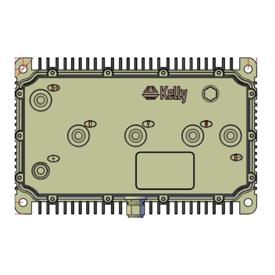
Kelly KLS-N Sinusoidal Brushless Permanent Magnet Motor Controller User’s Manual V2.9 Chapter 3 Wiring and Installation 3.1 Mounting the Controller The controller can be oriented in any position which should be as clean and dry as possible, and if necessary, shielded with a cover to protect it from water and contaminants. - Page 9 Kelly KLS-N Sinusoidal Brushless Permanent Magnet Motor Controller User’s Manual V2.9 Figure 8: KLS4875NC KLS7275NC KLS48100NC KLS72100NC KLS48120NC KLS72120NC mounting holes’ dimensions (dimensions in millimeters) +/B+/B-/U/V/W:M8...
- Page 10 Kelly KLS-N Sinusoidal Brushless Permanent Magnet Motor Controller User’s Manual V2.9 Figure 9: With Aluminum Liquid Cooling Heatsink at the bottom Only for 400A and above controllers mounting holes’ dimensions (dimensions in millimeters) +/B+/B-/U/V/W:M8...
-
Page 11: Connections
Kelly KLS-N Sinusoidal Brushless Permanent Magnet Motor Controller User’s Manual V2.9 3.2 Connections 3.2.1 Pin definition of KLS-N Controller waterproof connector Figure 10: 1,The switch signal is valid to 12V 2,12V only can be used for LED or switch signals. - Page 12 Kelly KLS-N Sinusoidal Brushless Permanent Magnet Motor Controller User’s Manual V2.9 (14) REV_SW: Reverse switch input. Orange (6) RTN: Signal return or power supply return. Black (12) FWD: Forward switch or can be enabled as High speed switch function. White (11) 12V:12V Source Red .
- Page 13 Kelly KLS-N Sinusoidal Brushless Permanent Magnet Motor Controller User’s Manual V2.9 3.2.2 Standard Wiring of KLS-N Controller Figure 11: KLS-N controller standard wiring (Battery voltage can be used for controller supply) 3.2.3 Optional wiring of KLS-N controller The 12V input signal of the pin supplies the second braking function of the controller.
- Page 14 Kelly KLS-N Sinusoidal Brushless Permanent Magnet Motor Controller User’s Manual V2.9 Figure 12: Wiring of brake switch(12V): 12V is provided by external source. Figure 13: Wiring of brake switch(12V): 12V is provided by KLS-N controller on pin11 Figure 14: Wiring diagram for motor temperature sensor NOTE: KLS controller can support KTY84-130/150 and KTY83-122 thermistors.
-
Page 15: Installation Check List
Kelly KLS-N Sinusoidal Brushless Permanent Magnet Motor Controller User’s Manual V2.9 Figure 16:SM-4P connector for communication interface on KLS-N controller 3.3 Installation Check List Before operating the vehicle, complete the following checkout procedure. Use buzzer code as a reference as listed in Table 1. -
Page 16: Chapter 4 Programmable Parameters
Kelly KLS-N Sinusoidal Brushless Permanent Magnet Motor Controller User’s Manual V2.9 acceleration and good power. Chapter 4 Programmable Parameters KLS Configuration program allow users to set parameters according to the vehicle actual working environment so as to be at its best. - Page 17 (7)TPS High Err: Hall active pedal, if higher than the value, report the fault of TPS Type. Range: 80~100 As you may know, the output of hall throttle from Kelly is about from 0.86V to 4.2V. Our controller will report 3.3 error code if the output of hall throttle is below 0.5V or above 4.5V by default.
- Page 18 Kelly KLS-N Sinusoidal Brushless Permanent Magnet Motor Controller User’s Manual V2.9 type at 2. As the same goes,it is valid to adjust the high threshold voltage above 4.5V or below 4.5V. Usually the hall output voltage is 4.2V Max.If you adjust it to lower value which is near 4.2V,it may trigger the error code in normal way.
- Page 19 Kelly KLS-N Sinusoidal Brushless Permanent Magnet Motor Controller User’s Manual V2.9 Range: 20~100 By default, it is set at 100%.Both F-N-R control and three speed function used the same pin12.Needless to say, we can not use both functions at the same time. Three Gears switch is supposed to enable F-N-R control.
- Page 20 Kelly KLS-N Sinusoidal Brushless Permanent Magnet Motor Controller User’s Manual V2.9 way. The motor speed will increase when the throttle is from 0V to 5V. If you enable joystick for this controller in user program, you will start the motor from 2.5V position.2.6V to 5V is forward.2.4V to 0V is backward.
-
Page 21: Step 2
Kelly KLS-N Sinusoidal Brushless Permanent Magnet Motor Controller User’s Manual V2.9 The boost function is still based on limiting of the motor current and battery current settings in user program. If disabled, the controller can provide brake sensor regen mode on the same pin as pin2.In simple, boost and brake analog regen used the same pin as pin2. -
Page 22: Step 3
Kelly KLS-N Sinusoidal Brushless Permanent Magnet Motor Controller User’s Manual V2.9 Suggestion: Set according to the real motor poles on the nameplate of the motor, factory default is at 8. (3)Speed Sensor Type: Speed Sensor Type, 2:Hal, 3:Resolver, 4:Line Hall. Range: 2~4 Different sensors type. - Page 23 Kelly KLS-N Sinusoidal Brushless Permanent Magnet Motor Controller User’s Manual V2.9 (5)Brake Time: Brake Time, the time of Brake Torque from 0 to max, accuracy 0.1s. Range: 1~250 Factory set is 15 (6)Brake Rls Time: Brake Release Time, the time of Brake Torque from max to 0, accuracy 0.1s.
-
Page 24: How To Use Identification Angle Operation Function
Kelly KLS-N Sinusoidal Brushless Permanent Magnet Motor Controller User’s Manual V2.9 (13)Torque Speed Kp:3000 Torque Speed Ki:80 Speed Err Limit:1000 These parameters are used for PID adjustment. If the acceleration is too aggressive, please reduce these three parameters at the same time, vice versa. Please change the Torque Speed Kp every 1000 units,Torque speed Ki every 100 units and Speed Err limit every 500 units. - Page 25 Kelly KLS-N Sinusoidal Brushless Permanent Magnet Motor Controller User’s Manual V2.9 2,Please connect the controller to user program by using an USB to RS232 cable and SM-4A DB9(RS232) Converter.
- Page 26 Kelly KLS-N Sinusoidal Brushless Permanent Magnet Motor Controller User’s Manual V2.9 Customers also can use a Z-TEK USB to RS232 cable and SM-4A DB9(RS232) Converter to connect the controller to an Android Tablet. The third option is customers can buy our Bluetooth converter to connect the controller to Android Phone.
- Page 27 Kelly KLS-N Sinusoidal Brushless Permanent Magnet Motor Controller User’s Manual V2.9 3,Please download the controller user program from our website for free. www.kellycontroller.com/support.php Please install the user program in your computer, Tablet or Phone. 4,Please turn on the key switch so that the controller can get power supply from B+/B- and Pin7.Please try to open the user program in your computer or other devices.
- Page 28 Kelly KLS-N Sinusoidal Brushless Permanent Magnet Motor Controller User’s Manual V2.9 9,Please turn off the power supply again. Please wait about a few seconds to turn on the power supply one more time. 10,Please try to connect the controller to user program again. You will see 85 in the identification angle item.
-
Page 29: Chapter 5 Maintenance
Identification angle operation. • Use a straight through RS232 cable or USB converter provided by Kelly to connect to a host computer. Provide >+18V to PWR(for a 24V controller, provide >+8V). Wire power supply return(supply negative) to any RTN pin. - Page 30 Kelly KLS-N Sinusoidal Brushless Permanent Magnet Motor Controller User’s Manual V2.9 Caution: •Make certain that the motor is connected before trying to run Identification angle function in the configuration software. The controller needs to be connected to batteries, motor and throttle before Identification operation. That is to say, it is not enough to connect only power supply(PWR=pin7) to batteries for Identification Angle operation.
- Page 31 Kelly KLS-N Sinusoidal Brushless Permanent Magnet Motor Controller User’s Manual V2.9 2. There may be excessive load on the +5V supply caused by too low a value of Regen or throttle potentiometers or incorrect wiring. 3. Controller is damaged. Contact Kelly about a warranty repair.
-
Page 32: Contact Us
Kelly KLS-N Sinusoidal Brushless Permanent Magnet Motor Controller User’s Manual V2.9 Contact Us: Kelly Controls Home Page: http://www.KellyController.com Download user manual,instructions and user program: www.kellycontroller.com/support.php E-mail: Sales@Kelly-Controls.com Phone: (01) 224 637 5092...
Need help?
Do you have a question about the KLS4860NE and is the answer not in the manual?
Questions and answers