
Subscribe to Our Youtube Channel
Related Manuals for Risco SecuSafe EL4855PI


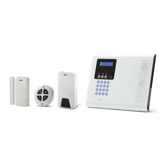
Summary of Contents for Risco SecuSafe EL4855PI
- Page 1 SecuSafe Quick Start Guide Visit us on the Web: www.riscogroup.com/el iOS app Android app RISCO Group website...
-
Page 2: Table Of Contents
Table of Contents GETTING STARTED....................4 ......................4 OMPONENTS ....................4 XPANDING YOUR YSTEM ....................... 4 YSTEM NSTALLATION IMPORTANT SAFETY PRECAUTIONS ................5 INITIAL SYSTEM SETUP ..................... 6 STEP 1: CONTROL PANEL WIRING AND PRE-INSTALLATION TASKS ......7 ................... 8 PENING THE ONTROL ANEL... - Page 3 STEP 9: ESTABLISHING SYSTEM COMMUNICATION ..........32 GPRS/GSM/IP C ................... 32 OMMUNICATION Connecting via GPRS ..................... 32 Connecting via IP ....................32 STEP 10: CONNECTING TO RISCO CLOUD ..............33 RISCO C ..................33 EGISTERING TO LOUD RISCO C ..................34...
-
Page 4: Getting Started
– up to a maximum of 34 zones (32 wireless) for detectors and sensors, 19 keyfobs, 4 repeaters (range extenders), 8 PIR camera-detectors, and more. Visit the RISCO website for more information at: www.riscogroup.com. -
Page 5: Important Safety Precautions
Important Safety Precautions WARNING: Installation or usage of this product that is not in accordance with the intended methods as described in the instructional/product materials and by the supplier can result in damage, injury, or death. WARNING: Make sure this product is not accessible by children and anyone for whom system operation is not intended. -
Page 6: Initial System Setup
Initial System Setup The following steps are required to initially set up your system for operation: Step 1: Control Panel Wiring and Pre-Installation Tasks Step 2: Installing the Control Panel Step 3: Powering Up the Control Panel Step 4: Selecting a Language Step 5: Registering Components Step 6: Installing Kit Components Step 7: Testing the System... -
Page 7: Step 1: Control Panel Wiring And Pre-Installation Tasks
Step 1: Control Panel Wiring and Pre-Installation Tasks IMPORTANT: Before performing any control panel wiring or other pre-installation tasks, make sure that the control panel is situated at a location that is close enough for all external connections as required, such as the electrical power supply (wall outlet or circuit breaker), the IP cable, and wired accessories. -
Page 8: Opening The Control Panel
Opening the Control Panel To open the control panel: Make sure the control panel is NOT connected to an electrical power supply, and then open the control panel. Make sure that both covers remain connected to each other with two plastic connecting strips and the ribbon cable: ... -
Page 9: Control Panel Modules
Control Panel Modules The two modules requiring wiring and/or other pre-installation tasks are located on the control panel’s back cover – the Communication module, and the Power and Connections module. Communication Module Communication module ... -
Page 10: Power And Connections Module
Power and Connections Module Terminal block (system connections): RS 485 PGM relay outputs (A & B) Wired detector zones ( 1& 2) Auxiliary output Cable clamp for power cable (clamp shown installed) Power supply terminals (230 VAC / 115 VAC / 9 VAC; 6VA input) ... -
Page 11: Installing The Sim Card
Installing the SIM Card To enable GPRS communication a SIM card must be inserted into its holder, located on the Communication module (see Communication Module, page 9). WARNING: If a SIM card is not pre-installed, insert it BEFORE connecting the electrical power supply to the control panel. ... -
Page 12: Connecting To The Network
3. Secure the AC power cable onto the Power and Connection module using the provided cable clamp, screw and washer: 4. At the Power and Connection module, perform all other relevant wiring tasks as required (see Power and Connections Module, page 10). - Page 13 Installation Procedure WARNING: Make sure the control panel is NOT connected to any electrical power supply. To install the control panel: Before mounting the control panel to the wall, route all the cables through the ducts on the back-side of the control panel: ...
- Page 14 Mount the control panel. If needed, you can temporarily mount it using the upper 2 screws only: Screw locations for temporary mounting Screw locations for permanent mounting 3. Close up the control panel casing, making sure the tabs on the cover fit into their respective grooves.
-
Page 15: Step 3: Powering-Up The Control Panel
Step 3: Powering-Up the Control Panel After installing the control panel), you can now power it up. To power-up the control panel: Apply electrical power to the control panel with the AC power cable (at the wall outlet or circuit breaker); the control panel display will then prompt you to select a language (see Step 4). -
Page 16: Step 5: Registering Components
Step 5: Registering Components All wireless system components such as detectors and accessories first need to be registered in order to be recognized by the system. Registering Kit-Supplied and Additional Components The following procedure is for enrolling the components included in the kit (other than keyfobs), as well as for enrolling additional components that are added on to expand the system. -
Page 17: Registering Keyfobs
b. Release the tamper switch; the following display: ZONE, the automatically-assigned zone number, and SAVE? 4. Press to save the registration; the control panel beeps and the automatically-assigned zone number displays. IMPORTANT: Write down the component / zone information for future reference (see Listing of Component / Zone Information, page 18). -
Page 18: Listing Of Component / Zone Information
Listing of Component / Zone Information When each wireless component is registered it is recommended to write down its information, as shown in the table below. This listing should be retained by the customer for future reference as it may be needed, for example, when performing a walk test, or to bypass zones. -
Page 19: Step 6: Installing Kit Components
3. Press ; a beep indicates it was deleted, and DELETE displays again to indicate the system is ready to delete the next component. 4. When finished with all deletions, press 5. One-at-a-time, for each component you are deleting, do the following: a. -
Page 20: Installing The Magnetic Contact Detector
Installing the Magnetic Contact Detector The magnetic contact detector has two parts – a transmitter, and a magnet. The magnetic detects door and window intrusion, and the additional input can be used for a universal transmitter (normally open), or with a pulse sensor device, such as a roller shutter. -
Page 21: Installation Procedure
Installation Procedure To install the transmitter and magnet:... - Page 22 -OR-...
-
Page 23: Installing Pir Detectors
Tamper Installing PIR Detectors The wireless PIR (“Passive Infra-Red” with “Pet Immunity”) detector and camera-detector models both detect movement for up to 11 meters (36.1feet) indoors. The pet immunity feature prevents alarms from being triggered by small pets. Mounting Guidelines Camera lens coverage: side view top view... - Page 24 Avoid mounting a PIR in a location where a pet can come within reach of the detector by climbing on furniture or other objects. PIR Model PET Model ft m PIR Pet - SIDE VIEW PIR - SIDE VIEW 9 10 11 12 13 14 15 9 10 11 12 PIR Pet - TOP VIEW PIR - TOP VIEW...
-
Page 25: Installation Procedure
Installation Procedure To install a PIR camera-detector: Tamper switch DIP switch Battery holder... - Page 26 NOTE: Retain the screw for use when re-installing the PCB An additional battery (purchased separately) can also be used to extend the operational duration (size CR123, 3 V, lithium). Check the RISCO Group website for information on battery updates.
-
Page 27: Step 7: Testing The System
Step 7: Testing the System It’s recommended to test all system components to ensure correct operation. Performing a Keyfob Test Test keyfobs by pressing the arming / disarming buttons to observe whether the respective chimes are heard, and whether the control panel display indicates arming/disarming. -
Page 28: Step 8: Defining System Users
Step 8: Defining System Users The system supports up to 32 users, and each user needs to be assigned a unique 4-digit user code. A valid user code is required to perform most system operations. NOTE: Controlled codes communicate system commands to the alarm receiving centre, whereas non-controlled codes do not communicate system commands to the alarm receiving centre. -
Page 29: Assigning, Editing, And Deleting Users (User Codes)
Assigning, Editing, and Deleting Users (User Codes) System users (user codes) are typically designated from MyELAS (see Step 10: Connecting to , page 33). Alternatively, they can be assigned from the control panel. NOTE: At initial system installation, it is highly recommended that the master user edits the master default code to be unique, and that it is kept confidential. -
Page 30: Defining Follow Me Destinations
Defining Follow Me Destinations You can designate the cell phone number of a system user to receive SMS Follow Me notifications of system events, such as alarm activations. For designating multiple SMS Follow Me numbers, refer to the SecuSafe Full Installation Manual. -
Page 31: Defining Keyfob, Component, And Zone Descriptors
Defining Keyfob, Component, and Zone Descriptors At the control panel, you can assign or edit a descriptive, identifying label (up to 16 characters) for all registered keyfobs, other peripheral system components, and zones. When assigning and editing descriptors, be sure to use the information in the Listing of Component / Zone Information, on page 18. -
Page 32: Step 9: Establishing System Communication
Step 9: Establishing System Communication GPRS/GSM/IP Communication Using GPRS as the primary communication channel (with IP as the backup) enables the Electronics Line Application Server (MyELAS) Cloud to handle all communication between the system and Smartphone / Web user applications. The Cloud enables remote system monitoring and control, such as system arming / disarming, receiving e-mail, SMS, and voice notifications, as well as viewing the event history log. -
Page 33: Step 10: Connecting To Risco Cloud
Step 10: Connecting to RISCO Cloud After connecting to the primary and backup communication channels, you will need to register first in order to log in to RISCO Cloud. Registering to RISCO Cloud To register to RISCO Cloud: 1. Go to www.riscocloud.com/register... -
Page 34: Logging In To Risco Cloud
(at the e-mail address defined as the Login name), and then click on the link. Logging in to RISCO Cloud You can also log in to RISCO Cloud from your Smartphone (see Using the Smartphone and Web User Applications, page 40). To log in to RISCO Cloud: 1. -
Page 35: Operating The System
Operating the System Before Using the System After completing all initial system setup steps, before you use the system, first check if any error messages still display on the control panel (use to scroll and view). If any remain, see Troubleshooting, page 41. Describing the Control Panel Keypad Control Panel Description... -
Page 36: Describing The Control Panel Leds
Describing the Control Panel LEDs Color State Status Both AC electrical power and battery power are disconnected System power status is ok (no system Green faults) Open (activated) zone. Check that the windows and doors are closed and no Green Flashing movement is detected by the detectors within the protected area. -
Page 37: Describing User Commands
Describing User Commands Commands to control and use the system (such as arming and disarming) are typically performed by system users at the control panel, keyfob, as well as via the Smartphone and Web user applications. Describing Arming Modes Full arming: For Partial arming: For Perimeter arming: For arming all of the... -
Page 38: Performing Commands From Control Panel And Keyfobs
Performing Commands from Control Panel and Keyfobs Command Control Panel Procedure Keyfob Procedure Full arm Press Press Press Press Partial arm Press Perimeter arm Press Disarm (and Enter user code Press silence alarms) Activate panic Press simultaneously; sounds alarm or Press &... -
Page 39: Performing Commands By Sms
Performing Commands by SMS [GPRS/GSM/IP only]: From a cell phone, users can send system commands via SMS. Command Description SMS Command Code Disarm Full arm Partial arm Perimeter arm Receive system arming status (master user only) To send a command by SMS: 1. -
Page 40: Using The Smartphone And Web User Applications
Using the Smartphone and Web User Applications Smartphone App The Smartphone MyELAS app will guide you through the operational instructions. Download from the Apple’s App Store for iOS devices, or from Google Play for Android devices. iOS app Android app Web App For operational instructions, refer to the MyELAS Web application documentation at:... -
Page 41: Troubleshooting
Troubleshooting The following are a list of error messages that may appear on the control panel display, along with the actions that can be performed for resolution. Trouble Message Description Corrective Action Verify that the DHCP option is DHCP service not enabled in your router. - Page 42 Trouble Message Description Corrective Action According to the keyfob number that LOW BATTERY The specified keyfob displays, replace the battery in the KEYFOB# battery is low. respective keyfob (see Replacing Keyfob Batteries, page 44). Check if the SIM card is Either the SIM card is GPRS-enabled (insert the SIM card MEDIA LOSS...
- Page 43 Trouble Message Description Corrective Action The cellular network is The cellular network needs to be down, reception is not restored, the control panel needs to be MEDIA LOSS GSM adequate, or the SIM relocated to a place with better card has a depleted reception, or the SIM card usage usage allowance.
-
Page 44: System Maintenance - Battery Replacement
System Maintenance — Battery Replacement The user can replace batteries for keyfobs, detectors and other accessories (but not the control panel’s battery). Check the EL website for information on battery updates. WARNING: Ensure a battery is replaced with the correct type and polarity. -
Page 45: Replacing Component Batteries
Replacing Component Batteries When replacing batteries in detectors and other system accessories (other than keyfobs), do the following to prevent activating the siren: NOTE: When replacing batteries, check the EL website for information on battery updates. To replace component batteries: From the control panel, press for about 3 seconds until REPLACE BATTERY! displays. -
Page 46: Product Specification
Product Specification General Technology 2-way wireless RF Wireless Zones 32 maximum 2 on-board, with up to 2 optional wired Wired zones zone expanders Wireless keyfobs 19 maximum Wireless keypads 4 maximum 2-way wireless repeaters (range extenders) 4 maximum PIR camera/detectors 8 maximum User codes 32 maximum... - Page 47 2-Way Video Verification PIR-PET Detector (PIR Camera) - Model EL4855PI Power 3 V lithium battery, size CR123 (x 2) Current consumption 200 mA capture with flash, 58 µA standby Sensor CMOS digital image sensor 14 m coverage (wide angle) with 90° Maximum coverage field-of-view Operating temperature...
-
Page 48: Certification And Standards
• Method of operation: Pass-through RED Compliance Statement: Hereby, RISCO Group declares that this equipment is in compliance with the essential requirements and other relevant provisions of Directive 2014/53/EU. For the CE Declaration of Conformity please refer to our website: www.riscogroup.com... -
Page 49: Standard Limited Product Warranty ("Limited Warranty")
RISCO, for a period of (i) 24 months from the date of delivery of the Product ( the “Warranty Period”). This Limited Warranty covers the Product only within the country where the Product was originally purchased and only covers Products purchased as new. - Page 50 Products “AS IS”. Software and applications distributed or made available by RISCO in conjunction with the Product (with or without the RISCO brand), including, but not limited to system software, as well as P2P services or any other service made available by RISCO in relation to the Product, are not covered...
-
Page 51: Contacting Your Engineer
Contacting your Engineer When in need of service, ordering components, or for questions related to the system, please retain this information for future use when contacting your engineer: Engineer name: _________________________________________ Engineer address, _________________________________________ telephone, e-mail: _________________________________________ Hours of business: _________________________________________ Website: Other information:... -
Page 52: Contacting Risco Group
Contacting RISCO Group International Headquarters: RISCO Group 14 Hachoma St., 75655 Rishon Le Zion, Israel Tel: (+972-3) 963-7777 Please visit us at: www.riscogroup.com Copyright 2019, RISCO Group All rights reserved. 5IN2646 D 10/2019...
Need help?
Do you have a question about the SecuSafe EL4855PI and is the answer not in the manual?
Questions and answers