Table of Contents
Advertisement
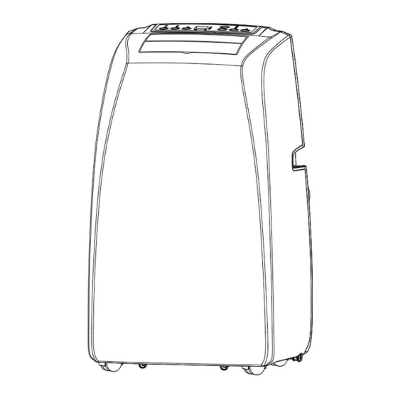
Portable Air Conditioner
Installation and User Manual
MODEL NO.: NPE8-08C/X1E
Thank you for purchasing this product. This user manual will provide you with valuable information necessary for the
proper care and maintenance of your new product. Please take a few moments to thoroughly read the instructions and
familiarize yourself with all the operational aspects of your new Portable Air Conditioner.
Advertisement
Table of Contents

Subscribe to Our Youtube Channel
Related Manuals for air choice NPE8-08C/X1E


Summary of Contents for air choice NPE8-08C/X1E
- Page 1 Portable Air Conditioner Installation and User Manual MODEL NO.: NPE8-08C/X1E Thank you for purchasing this product. This user manual will provide you with valuable information necessary for the proper care and maintenance of your new product. Please take a few moments to thoroughly read the instructions and...
-
Page 2: Air Conditioner Safety
AIR CONDITIONER SAFETY Your safety and the safety of others are very important. We have provided many important safety messages in this manual and on your appliance. Always read and obey all safety messages. This is the safety alert symbol. This symbol alerts you to potential hazards that can kill or hurt you and others. - Page 3 damaged or dropped. The air conditioner should be serviced only by qualified service personnel. Call an authorized service company for examination, repair, or adjustment. Disconnect the power before servicing. Disconnect the power before cleaning. NOTE: Turning off the power by pressing the Power button does NOT disconnect the appliance from the power supply.
- Page 4 the permissible voltage and current permitted for the equipment in use. Intrinsically safe components are the only types that can be worked on while living in the presence of a flammable atmosphere. The test apparatus shall be at the correct rating. Replace components only with parts specified by the manufacturer. Other parts may result in the ignition of refrigerant in the atmosphere from a leak.
- Page 5 If a vacuum is not possible, make a manifold so that refrigerant can be removed from various parts of the system. Make sure that cylinder is situated on the scales before recovery takes place. Start the recovery machine and operate in accordance with manufacturer's instructions. Do not overfill cylinders.
- Page 6 sensorielles ou mentales réduites s'ils ont reçu une supervision ou des instructions concernant l'utilisation de l'appareil en toute sécurité et comprennent les risques encourus. Les enfants ne doivent pas jouer avec l'appareil. Le nettoyage et l'entretien ne doivent pas être effectués par des enfants sans surveillance. Cet appareil n'est pas destiné...
- Page 7 En aucun cas, des sources potentielles d'inflammation ne doivent être utilisées pour rechercher ou détecter des fuites de réfrigérant. Une torche aux halogénures (ou tout autre détecteur utilisant une flamme nue) ne doit pas être utilisée. Des détecteurs de fuites électroniques doivent être utilisés pour détecter les réfrigérants inflammables, mais la ...
- Page 8 Si un vide n'est pas possible, créez un collecteur afin que le réfrigérant puisse être retiré de diverses parties du système. Assurez-vous que le cylindre est situé sur la balance avant de procéder à la récupération.Start the recovery machine and operate in accordance with manufacturer's instructions. Ne pas trop remplir les cylindres.
-
Page 9: Parts And Features
PARTS AND FEATURES Control Panel 11. Up filter assemble Horizontal louver 12. Down filter assemble Front shell 13. Chassis Universal wheel 14. Remote control Back shell 15. Connector Hand 16. Exhaust hose Filter 17. Adapter Universal socket 18. Window kits Wire winding pillar 19. - Page 10 INSATALLATION REQUIREMENTS TOOLS AND PARTS Gather the required tools and parts before starting installation. TOOLS NEEDED •Flat-blade Screwdriver •Phillips Screwdriver LOCATION REQUIREMENTS Place the air conditioner on a flat, level surface in a location that is at least 50 cm from any wall. NOTE: A minimum clearance of 50 cm from the air conditioner to the wall must be maintained to ensure proper airflow.
-
Page 11: Power Supply Cord
POWER SUPPLY CORD Wiring Requirements • 115 Volt, 60Hz, 15-amp fused grounded 3 prong outlet • The use of a time-delay fuse or time-delay circuit breaker is recommended. • Use a dedicated circuit only. NOTE: Do not operate any other electrical appliances on this circuit or you may trip the circuit breaker/fuse. If this power supply cord is damaged, it cannot be repaired. - Page 12 STEP 2 - TWIST THE EXHAUST HOSE CONNECTOR ONTO EXHAUST HOSE A. Take out the exhaust hose and air-in duct assembly and their adapters from plastic bag. B. Extend the exhaust hose at one end, screw the round end of adapter into exhaust hose at anticlockwise direction. C.
- Page 13 Lock the butterfly nut on panel A, and do not lock the butterfly nut tightly, keeping the spacing of 2.5mm. Connect with panel B, adjust the panel(s) to the width or height of the window as shown. Fasten the butterfly nut to fix the window slide set.
- Page 14 STEP 4 - Install the seal plates on the Window A. Open the window, put the seal plates on it. B. Adjust the length of seal plates according to the window height. STEP 5 - COMPLETE INSTALLATION Move the unit together with its exhaust hose assembly in front of the window and keep the unit at least 50 cm away from the walls or other objects.
- Page 15 NOTE: Some window installations may require the extension panels to be trimmed. Slide the adapter downwards and assure adapter installed in good position. Assure the slant panel direction to match seal-plate direction. Exhaust hose cannot be bent or with flexure higher than 45°, in order to keep good ventilation of exhaust hose. WARNING Electrical Shock Hazard Plug into a grounded 3-prong outlet.
-
Page 16: Control Panel
CONTROL PANEL BUTTONS TIMER BUTTON Program the time from 1 hour to 24 hours for the unit to turn ON or OFF. When a TIME DELAY is programmed, the Timer indicator light will illuminate. While the unit is operating: Press the TIMER button. Press the UP/DOWN arrow buttons to select the number of hours you want the unit to continue to operate before turning off. - Page 17 To set the temperature: The temperature can be set between 62 ℉ and 86 ℉ (17 ℃ and 30 ℃ ) when the air conditioner is in COOL mode. Press the MODE button until the COOL mode is selected. Press the UP or DOWN ARROW buttons to select the temperature. Note: The temperature cannot be set when the air conditioner is in wither FAN or DRY mode.
- Page 18 Auto Swing: Press this button to open or close auto swing function. 2) Battery installation: Before using your remote control, install the AAA batteries into remote control. Press and glide the battery cover on the back of the remote control, then you can remove the cover. Insert two new alkaline AAA batteries into the battery compartment.
-
Page 19: Protection Functions
Protection functions Water-full protect: Use Water switch to achieve water-full protect, water switch is always off, it will be on when it works. Both water-full indicator and “FL” on LED window is flashing. Anti-freeze protection function: Compressor, water spraying motor will turn off when compressors are running over 10 minutes and tube temperature (Tp) is continuously ≦... -
Page 20: Safety Protections
SAFETY PROTECTIONS 1. Water-full safety alarm and shut – off protection function When the water volume exceeds its alarm level in the chassis a warning sounds automatically and water-full icon is lights up in the display. You need to drain the water and re-start the unit. (Please, for more information about how to drain, refer to the “Drainage Instruction”). - Page 21 DRAIN THE INTERNAL WATER This portable air conditioner has two drain ports, higher one and lower one and we can use two drainage methods: manual drainage and continuous drainage. Manual Drain This unit is designed with a highly efficient self-evaporative system, and It is suggested to use manual drainage in cooling mode, all condensate will be recycled in the unit to ensure enough water to recycle in the unit to cool condenser and enhance cooling performance advance;...
- Page 22 Keep the drain cover and its stopper properly installed when continuous drainage is adopted. Water outlet Drain hose Drain cover higher drain port is the best. Continuous drain in dehumidification mode: Screw off the drain cover and unplug the water stopper. Connect drain-hole with φ13mm PVC drain hose, into depth of 8mm-10mm (as Photo 18).
-
Page 23: Maintenance And Service
Maintenance and Service Turn off the unit and pull out the plug before maintenance or send the unit to service center. Surface cleaning Clean the unit surface with a wet and soft cloth, but do not use chemical solvents such as alcohol or gasoline to avoid any damage to the unit. - Page 24 2) Clean the handle position and remote control storage area with a wet and soft cloth. Note:Do not drip water into the unit. End of Season Storage Screw off the drain cover, and then pull out the stopper to completely drain the water. Note:The tilt angle of the unit must be≦30 、...
-
Page 25: Troubleshooting
Troubleshooting Please check the unit and suggestions below before asking for professional service, but never dismantle or repair the unit by yourself, it may cause harm to you and your property. Trouble Cause Remedy Connect the unit to a live socket and turn Power supply failure. - Page 26 Schematic diagram of the air conditioner Capillary Condenser Compressor Evaporator For specific technical parameters of the model, refer to rating label on the product. Correct Disposal of this product This marking indicates that the product should not be disposed of with other household wastes throughout the world. To prevent possible harm to the environment or human health from uncontrolled waste disposal, recycle it responsibly to promote the sustainable reuse of material resources.
-
Page 27: Warranty
ONE (1) YEAR from the date of purchase by the original purchaser (“Warranty Period”). If a defect arises and a valid claim is received within the Warranty Period, at its option, AIR CHOICE will either 1) repair the defect at no charge, using new or refurbished replacement parts, or 2) replace the product with a new product that is at least functionally equivalent to the original product, or provide a store credit in the amount of the purchase price of the original product. - Page 28 CONTACT US Thank you for choosing AIR CHOICE product. For any questions about your product or honor your warranty, please try the following methods to get in touch with us: 1. Scan the QR code below; 2. Write us at [airchoice@afterservice.vip];...
Need help?
Do you have a question about the NPE8-08C/X1E and is the answer not in the manual?
Questions and answers