
Subscribe to Our Youtube Channel
Related Manuals for Power Fist 8536773


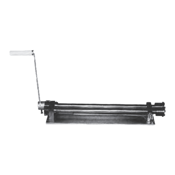
Summary of Contents for Power Fist 8536773
- Page 1 8536773 18-1/4 in. Bead Roller Kit User Manual Please read and understand all instructions before use. Retain this manual for future reference.
-
Page 2: Specifications
8536773 18-1/4 in. Bead Roller Kit SPECIFICATIONS Bead & Flange 1.2/18 Capacity (mm/gauge) Shear 1.2/18 464//18-1/4 Throat (mm//in) //in //in Bead mandrels sizes(mm//in) 6.35//1/4,9//3/8,12.7//1/2 Flange mandrels sizes(mm//in) 1.6//1/16,3//1/8,6.35//1/4 Shearing Mandrel Quantity 1 set 23/23.5 N.W./G.W.(Kg) SAVE THIS MANUAL You will need the manual for the safety warnings and precautions, assembly instructions, operating and maintenance procedures, parts list and diagram. - Page 3 18-1/4 IN. BEAD ROLLER KIT 8536773 7. Dress properly. Do not wear loose clothing or jewelry as they can be caught in moving parts. Protective, electrically non-conductive clothes and non-skid footwear are recommended when working. Wear restrictive hair covering to contain long hair.
-
Page 4: Operation
8536773 18-1/4 IN. BEAD ROLLER KIT UNPACKING When unpacking, check to make sure that all parts shown in the Parts Diagram are included. If any parts are missing or broken, please contact the seller. ASSEMBLY 1. Place the Bead Roller Kit into a Vise as shown in Figure 1 . Securely tighten the Vise to hold the machine . - Page 5 18-1/4 IN. BEAD ROLLER KIT 8536773 Figure 2 4. Slide the Driving Shaft(3#) until the edges of the Cutting Plates(9#) are touching. 5. By hand,move Collar(6#) on the Driving Shaft(3#) so its edge is touching the Roll Block(2#) and tighten its Screws(16#).
- Page 6 18-1/4 IN. BEAD ROLLER KIT 8536773 4. Using a wrench, remove the two Blots(14#) securing the Cutting Dies(10#-01,10#-02) to the Driving Shaft(3#) and Driving Shaft(4#) .Remove the Washers(13#). 5. Using a Hex Key Wrench(27#),loosen the Screws(16#) taht lock the Cutting Dies (10#-01,10#-02)onto the rollers.
-
Page 7: Please Read The Following Carefully
18-1/4 IN. BEAD ROLLER KIT 8536773 Figure 5 DIES SELECTION GUIDE Note:Dies are larger than shown in this illustration 1/4” Half-Round Die 3/8” Half-Round Die 1/2” Half-Round Die (21) (20) (19) 1/4” Flange Die 1/16” Flange Die 1/8” Flange Die... -
Page 8: Parts Diagram
18-1/4 IN. BEAD ROLLER KIT 8536773 PARTS DIAGRAM For technical questions call: 1-800-665-8685... -
Page 9: Parts List
18-1/4 IN. BEAD ROLLER KIT 8536773 PARTS LIST Description Part No. Part No. Description Handle Cover Base Screw M6x16 Roll Block Driving Shaft 19-01 1/2” Half-Round Dies(Convex) Driving Shaft 19-02 1/2” Half-Round Dies(Concave) Gear 20-01 3/8” Half-Round Dies(Convex) 3/8” Half-Round Dies(Concave) - Page 10 8536773 Trousse de rouleaux de 18 1/4 po ARTICLE Manuel d'utilisateur Vous devez lire et comprendre toutes les instructions avant d'utiliser l'appareil. Conservez ce manuel afin de pouvoir le consulter plus tard.
-
Page 11: Spécifications
8536773 Trousse de rouleaux de 18 1/4 po SPÉCIFICATIONS Talon et collerette 1,2/18 Capacité (mm/jauge) Cisaille 1,2/18 Col (mm//po) 464//18 1/4 //in Dimension de la garniture (mm//po) 710 x 250 x 100//28 x 9 13/16 x 3 15/16 Tailles des mandrins pour talons (mm//po) - Page 12 TROUSSE DE ROULEAUX DE 18 1/4 po 8536773 7. Portez des vêtements appropriés. Ne portez pas de vêtements amples ni de bijoux, car ils peuvent rester coincés dans les pièces mobiles. Des vêtements de protection non conducteurs d'électricité et des chaussures antidérapantes sont recommandés pour le travail.
- Page 13 TROUSSE DE ROULEAUX DE 18 1/4 po 8536773 DÉBALLAGE Lors du déballage, assurez-vous que toutes les pièces apparaissant sur le diagramme des pièces sont comprises. Si une ou plusieurs pièces sont manquantes ou endommagées, veuillez communiquer avec le vendeur. ASSEMBLAGE 1.
- Page 14 TROUSSE DE ROULEAUX DE 18 1/4 po 8536773 Figure 2 4. Glissez l'arbre d'entraînement (n o 3) jusqu'à ce que les rebords des plaques à découper (n o 9) se touchent. 5. Déplacez le collier (n o 6) à la main sur l'arbre d'entraînement (n o 3) de façon à ce que son rebord touche le bloc de rouleau (n o 2) et serrez ses vis (n o 16).
- Page 15 TROUSSE DE ROULEAUX DE 18 1/4 po 8536773 3. Enlevez les plaques à découper (n o 9). 4. Au moyen d'une clé, enlevez les deux boulons (n o 14) retenant les matrices à découper (n o 10-01, n o 10-02) à l'arbre d'entraînement (n o 3) et à l'arbre mené (n o 4). Enlevez les rondelles (n o 13).
- Page 16 TROUSSE DE ROULEAUX DE 18 1/4 po 8536773 Figure 5 VEUILLEZ LIRE CE QUI SUIT ATTENTIVEMENT. LE FABRICANT ET/OU LE DISTRIBUTEUR PRÉSENTENT LE DIAGRAMME DES PIÈCES CON TENU DANS CE MANUEL EN GUISE DE RÉFÉRENCE SEULEMENT. NI LE FABRICANT, NI LE DISTRIBUTEUR NE PRÉSENTENT À...
-
Page 17: Diagramme Des Pièces
TROUSSE DE ROULEAUX DE 18 1/4 po 8536773 DIAGRAMME DES PIÈCES En cas de questions techniques, appelez le 1-800-665-8685... -
Page 18: Liste Des Pièces
8536773 TROUSSE DE ROULEAUX DE 18 1/4 po LISTE DES PIÈCES N o de N o de pièce Description Qté Description Qté pièce 19-01 Matrice demi-ronde de 1/2 Base po (convexe) Bloc de rouleau 19-02 Matrice demi-ronde de 1/2 Arbre d'entraînement po (concave) Arbre mené...
Need help?
Do you have a question about the 8536773 and is the answer not in the manual?
Questions and answers