
Subscribe to Our Youtube Channel
Related Manuals for NXP Semiconductors FRDM-PF1510EVM


Summary of Contents for NXP Semiconductors FRDM-PF1510EVM
-
Page 1: Frdm-Pf1510Evm
KTFRDMPF1510EVMUG FRDM-PF1510EVM evaluation board Rev. 1.0 — 18 June 2018 User guide FRDM-PF1510EVM... -
Page 2: Important Notice
KTFRDMPF1510EVMUG NXP Semiconductors FRDM-PF1510EVM evaluation board Important notice NXP provides the enclosed product(s) under the following conditions: This evaluation kit is intended for use of ENGINEERING DEVELOPMENT OR EVALUATION PURPOSES ONLY. It is provided as a sample IC pre-soldered to a printed circuit board to make it easier to access inputs, outputs, and supply terminals. -
Page 3: Overview Of The Pf1510 Pmic Development Environment
NXP offers a combination of boards that support the evaluation of the PF1510 power management integrated circuit (PMIC). The FRDM-PF1510EVM boards serve as an evaluation platform that allows users to test and demo designs that incorporate the PF1510 PMIC. The evaluation board contains a preconfigured MC32PF1510A4EP device and provides numerous jumpers and test points that allow users to tailor the evaluation to their needs. -
Page 4: Required Equipment
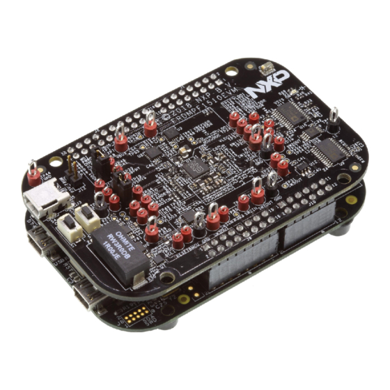
Getting to know the hardware 5.1 Board overview The FRDM-PF1510EVM board is an easy-to-use circuit board, allowing the user to exercise all the functions of the PF1510 PMIC. The FRDM-KL25Z is mounted to the EVB as an integral component and serves as an interface between the KITPF1510GUI and the PF1510 PMIC. -
Page 5: Device Description
KTFRDMPF1510EVMUG NXP Semiconductors FRDM-PF1510EVM evaluation board 5.3.1 Device description The PF1510 device populated on board features the A4 OTP; see Table Table 2. Startup configuration Register Pre-programmed OTP configuration – A4 configuration OTP_VSNVS_VOLT[2:0] 3.0 V OTP_SW1_VOLT[5:0] 1.1 V OTP_SW1_PWRUP_SEQ[2:0] OTP_SW2_VOLT[5:0] 1.2 V... -
Page 6: Board Description
USBPHY LDO enabled OTP_USBPHY USBPHY = 3.3 V OTP_ACTDISPHY USBPHY active discharge enabled 5.4 Board description Figure 1 describes the main elements on the FRDM-PF1510EVM. Figure 1. Board description Table 3. Board description Number Name Description 1A ELOAD electronic load 1.0 A... -
Page 7: Led Description
KTFRDMPF1510EVMUG NXP Semiconductors FRDM-PF1510EVM evaluation board 5.4.1 LED description The following LED is provided as visual output device for the board: Figure 2. LED location Table 4. LED description LED ID Description red LED, VSYS on state indicator KTFRDMPF1510EVMUG All information provided in this document is subject to legal disclaimers. -
Page 8: Jumper And Switch Definitions
KTFRDMPF1510EVMUG NXP Semiconductors FRDM-PF1510EVM evaluation board 5.4.2 Jumper and switch definitions Figure 3 shows the location of jumpers and switches on the evaluation board. Figure 3. Jumper and switch locations Table 5 describes the function and settings for each jumper and switch. -
Page 9: Test Point Definitions
KTFRDMPF1510EVMUG NXP Semiconductors FRDM-PF1510EVM evaluation board 5.4.3 Test point definitions The following test points provide access to various signals to and from the board. Figure 4. Test point locations Table 6. Test point definitions Test point name Signal name Description VIN_PORT 5.0 V power supply (from USB connector J3) -
Page 10: Frdm-Kl25Z Freedom Development Platform
FRDM‑PF1510EVM kit because of its low cost and features. The FRDM-KL25Z board uses the USB, built-in LEDs, and I/O ports available with NXPs Kinetis KL2x family of microcontrollers. The FRDM-PF1510EVM connects to the FRDM-KL25Z using the four dual row Arduino R3 connectors on the bottom of the board. KTFRDMPF1510EVMUG All information provided in this document is subject to legal disclaimers. - Page 11 KTFRDMPF1510EVMUG NXP Semiconductors FRDM-PF1510EVM evaluation board Figure 5. Connecting the FRDM-KL25Z to the FRDM-PF1510EVM Table 7. FRDM-PF1510EVM to FRDM-KL25Z connections FRDM-PF1510EVM FRDM-KL25Z Pin hardware name Description Header Header FRDM-PF1510EVM FRDM-KL25Z n.c. PTC7 not connected INTB PTA1 interrupt to the MCU n.c. PTC0...
- Page 12 KTFRDMPF1510EVMUG NXP Semiconductors FRDM-PF1510EVM evaluation board FRDM-PF1510EVM FRDM-KL25Z Pin hardware name Description Header Header FRDM-PF1510EVM FRDM-KL25Z n.c. PTC13 not connected STANDBY PTD5 STANDBY input n.c. PTC16 not connected RESETBMCU PTD0 MCU reset signal n.c. PTC17 not connected VSYS_CSA_ALERT PTD2 alert signal from the VSYS...
-
Page 13: Installing The Software And Setting Up The Hardware
KTFRDMPF1510EVMUG NXP Semiconductors FRDM-PF1510EVM evaluation board FRDM-PF1510EVM FRDM-KL25Z Pin hardware name Description Header Header FRDM-PF1510EVM FRDM-KL25Z n.c. PTB9 not connected P3V3 3.3 V coming from the Freedom board n.c. PTB10 not connected P3V3 RESET/PTA20 3.3 V coming from the Freedom board n.c. -
Page 14: Configuring The Hardware And Using The Gui For Control And Monitoring
KTFRDMPF1510EVMUG NXP Semiconductors FRDM-PF1510EVM evaluation board 7.2 Configuring the hardware and using the GUI for control and monitoring Figure 6. Hardware configuration 1. Apply input voltage to the board. • First solution is to use power directly from the FRDM-KL25Z by connecting J12 jumper. - Page 15 KTFRDMPF1510EVMUG NXP Semiconductors FRDM-PF1510EVM evaluation board 6. Enable the communication by clicking the Target Enabled: checkbox. The window turns from gray to color. 7. The GUI installation and hardware setup now are complete. KTFRDMPF1510EVMUG All information provided in this document is subject to legal disclaimers.
-
Page 16: Understanding And Using The Gui
KTFRDMPF1510EVMUG NXP Semiconductors FRDM-PF1510EVM evaluation board 7.3 Understanding and using the GUI 7.3.1 GUI structure for PF1510 Figure 7 shows the different components of the GUI. Figure 7. GUI components 7.3.2 GUI panels When the GUI is launched, it looks for a PF1510 target board connected via the USB cable. - Page 17 KTFRDMPF1510EVMUG NXP Semiconductors FRDM-PF1510EVM evaluation board Figure 8. GUI startup Pressing the Scan For Devices button attempts to read from each of the eight permissible I C-bus device addresses. The results are displayed in the main log window. If multiple PMIC devices are detected, the GUI can be configured to communicate with a particular device by selecting the corresponding device address.
-
Page 18: Switching Supplies Panel
KTFRDMPF1510EVMUG NXP Semiconductors FRDM-PF1510EVM evaluation board 7.3.3 Switching supplies panel The switching supplies panel allows users to adjust the functional parameters of each supply. Figure 10. Switching supplies panel To change supply parameters, click and adjust the desired control. An Update button appears whenever a change is made, and pressing the Update button writes the change to the PMIC. -
Page 19: Linear Supplies Panel
KTFRDMPF1510EVMUG NXP Semiconductors FRDM-PF1510EVM evaluation board 7.3.4 Linear supplies panel The linear supplies panel allows users to adjust the functional parameters of each linear regulator. To change supply parameters, click and adjust the desired control. Figure 11. Linear supplies panel An Update button appears whenever a change is made, and pressing the Update button writes the change to the PMIC. -
Page 20: Otp Configuration Panel
KTFRDMPF1510EVMUG NXP Semiconductors FRDM-PF1510EVM evaluation board 7.3.5 OTP configuration panel The OTP configuration panel allows access and editing of the PF1510 startup parameters. Figure 12. OTP configuration panel Initially, the panel display is the OTP configuration read from PMIC PF1510. The Load CFG File button opens the configuration file open dialog, and populates the panel with the parameters contained in this file. -
Page 21: Miscellaneous Panel
KTFRDMPF1510EVMUG NXP Semiconductors FRDM-PF1510EVM evaluation board 7.3.6 Miscellaneous panel The miscellaneous panel contains general-purpose commands and power up and down sequencing configuration. Figure 13. Miscellaneous panel KTFRDMPF1510EVMUG All information provided in this document is subject to legal disclaimers. © NXP B.V. 2018. All rights reserved. -
Page 22: Interrupts Panel
KTFRDMPF1510EVMUG NXP Semiconductors FRDM-PF1510EVM evaluation board 7.3.7 Interrupts panel The interrupts panel displays the state of all PF1510 interrupts. Figure 14. Interrupts panel The Interrupts tab displays status, mask, and sense registers for INT0, INT1, INT3, and INT4. Selecting the Poll Interrupts checkbox enables update of this information with period of 500 ms. -
Page 23: Script Editor Panel
KTFRDMPF1510EVMUG NXP Semiconductors FRDM-PF1510EVM evaluation board 7.3.8 Script editor panel The script editor panel allows the user to write and execute scripts that exercise various functions on the PF1510 PMIC. These functions include setting voltages on the regulators, reading and writing I C-bus addresses, and clearing interrupts. -
Page 24: Functional Registers Panel
KTFRDMPF1510EVMUG NXP Semiconductors FRDM-PF1510EVM evaluation board 7.3.9 Functional registers panel In the functional registers panel, clicking a checkbox immediately sets or clears the corresponding register bit. Key bit fields in each register are decoded to help displaying the actual state of each parameter. -
Page 25: Otp Registers Panel
KTFRDMPF1510EVMUG NXP Semiconductors FRDM-PF1510EVM evaluation board 7.3.10 OTP registers panel The OTP registers panel provides bit-level access to each register. Figure 17. OTP registers panel Clicking a checkbox immediately sets or clears the corresponding register bit. Key bit fields in each register are decoded to help displaying the actual state of each parameter. -
Page 26: Schematics, Board Layout And Bill Of Materials
KTFRDMPF1510EVMUG NXP Semiconductors FRDM-PF1510EVM evaluation board Schematics, board layout and bill of materials Schematics, board layout and bill of materials are available on the tool summary page: http://www.nxp.com/FRDM-PF1510EVM. References Following are URLs where you can obtain information on related NXP products and... -
Page 27: Legal Information
NXP Semiconductors and its suppliers accept no liability for inclusion and/or use of NXP Semiconductors products in such equipment or applications and therefore such inclusion and/or use is at the customer's own 11.2 Disclaimers... - Page 28 KTFRDMPF1510EVMUG NXP Semiconductors FRDM-PF1510EVM evaluation board Tables Tab. 1. Device features ..........4 Tab. 5. Jumper and switch definitions ......8 Tab. 2. Startup configuration ......... 5 Tab. 6. Test point definitions ......... 9 Tab. 3. Board description ..........6 Tab.
-
Page 29: Table Of Contents
KTFRDMPF1510EVMUG NXP Semiconductors FRDM-PF1510EVM evaluation board Contents FRDM-PF1510EVM ..........1 Important notice ..........2 Overview of the PF1510 PMIC development environment ............3 Getting started ............ 3 Kit content/packing list ........3 Required equipment .......... 4 System requirements .........4 Getting to know the hardware ......4 Board overview ..........4...
Need help?
Do you have a question about the FRDM-PF1510EVM and is the answer not in the manual?
Questions and answers