
Related Manuals for Ten-Tec 418


Summary of Contents for Ten-Tec 418
- Page 1 OPERATOR’S MANUAL MODEL 418 Users manual Release 1.03 – December 12, 2012 Part #74468 Printed in USA...
-
Page 2: Table Of Contents
3.3. Fuse ___________________________________________________________________________ 9 3.4. Antennas _______________________________________________________________________ 9 3.5 Key In / Out_____________________________________________________________________ 9 Amplifier Connections ______________________________________________________ 10 4.1. 418 to 539 Argonaut VI __________________________________________________________ 10 4.2. 418 to Other Rigs _______________________________________________________________ 10 Fault ____________________________________________________________________ 12 5.1. Fault conditions ________________________________________________________________ 12 5.2. - Page 3 NOTES: 418 Users manual Release 1.03 – December 12, 2012 Part #74468 Printed in USA...
-
Page 4: Your New 418
The additional hardware and accessories listed in Fig 1.3-1 come standard with your 1.1. Unpacking 418 new 418. Look over the items listed and refer to the 5 digit TEN-TEC part number and description should you find the need to Examine the 418 for signs of shipping replace an accessory. -
Page 5: Connection To Antenna & Power Supply
Receive signals regulated DC voltage. The supply voltage on are routed through the antenna connectors the 418 is 13.8 Vdc nominal +/- 15% to allow (Ant 1-2 or Ant 6) along to the antenna relays for mobile and battery operation. -
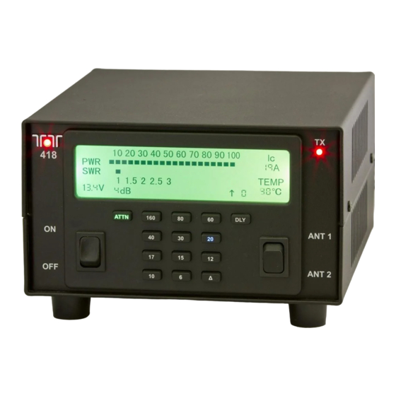
Page 6: Front Panel
This switch selects either Antenna 1 or The ATTENUATOR button can used to Antenna 2. The 6 Meter antenna is always lower the output power of the 418 when less selected when the amplifier is on 6 Meters than 100 watt output is desired. -
Page 7: Delta Button
When the delta button is pressed and lit the color and brightness, pressing the DELTA amplifier looks for data coming in on the button will save these setting and put the 418 ACC 1 connector for band selection. If there in normal operation mode. -
Page 8: Rear Panel
3. 418 Rear Panel 3.1. ACC 1 The 418 is equipped with an 8 pin accessory The pin out and function are listed in the connector. Refer to following figure for the following table. pin definitions as viewed from the rear of the amplifier. -
Page 9: Power
The tip is used as the key input to key voltage source must be capable of supplying the 418 and the ring is used as a key out for 23 amperes continuous duty other configurations. The key out has a 4 millisecond delay to allow the amplifier’s... -
Page 10: Amplifier Connections
4. Amplifier Connections 4.1. 418 to 539 Argonaut VI The 418 can be interfaced to the 539 using only the 8 pin din cable. The 539 will control band changes and keying the amplifier 4.2. 418 to Other Rigs The 1/8” key jack provides a key input on the tip and a key output on the ring to allow the 418 to key other transceivers. - Page 11 CW AND SSB OPERATION CW OPERATION Cable number 46216 418 Users manual Release 1.03 – December 12, 2012 Part #74468 Printed in USA...
-
Page 12: Fault
To correct tune inside of the ham band on radio and press one of the band buttons on the 418. For unusual problems a master reset can be done. Press and hold the ATTN button and turn on power, release the ATTN button. -
Page 13: Specifications
Display: Custom FSTN monochrome Display Backlight: 6 LEDS RF Power Output: 100 W, +/- 1 dB CW & SSB Duty Cycle: continuous service @ 100W 418 Users manual Release 1.03 – December 12, 2012 Part #74468 Printed in USA... -
Page 14: Block Diagram
CLK,DAT,ENA(KEYPAD) EEPROM KEY PAD POWER RELAY 13.8VDC ANTENNA SWITCH IN/OUT REGULATORS POWER RELAY FAN CONTROL 1/8" JACK CONTROL 5V,3.3V POWER SWITCH ACC 1 8 PIN DIN 418 Users manual Release 1.03 – December 12, 2012 Part #74468 Printed in USA... -
Page 15: In Case Of Difficulty
SWR due to antenna or feedline problems. some potential difficulties. Check the Power to the 418 can be restored by cycling obvious. Is your DC power source stable? the power switch off and on or the 13.8 Vdc Check power supply, all the cable and look source off and on. - Page 16 • Connect the equipment into an outlet on a circuit different from that to which the receiver is connected. • Consult TEN-TEC service for technical assistance (865) 428-0364 418 Users manual Release 1.03 – December 12, 2012...
-
Page 17: Addendum A (Added November 6, 2012)
Addendum A (Added November 6, 2012) A change was made to the software of the 418 to permit a customer to bypass the feature where the 418 will automatically select the 6 meter antenna, and permit it to follow the two position switch for antenna 1 vs antenna 2. - Page 18 EXCLUSIONS. This warranty does not cover damage resulting from misuse, lightning, excess voltages, polarity errors or damage resulting from modifications not recommended or approved by Ten-Tec. In the event of transportation damage, a claim must be filed with the carrier. Under no circumstances is Ten-Tec liable for consequential damages to persons or property caused by the use of this equipment.
Need help?
Do you have a question about the 418 and is the answer not in the manual?
Questions and answers