Table of Contents
Advertisement
Quick Links
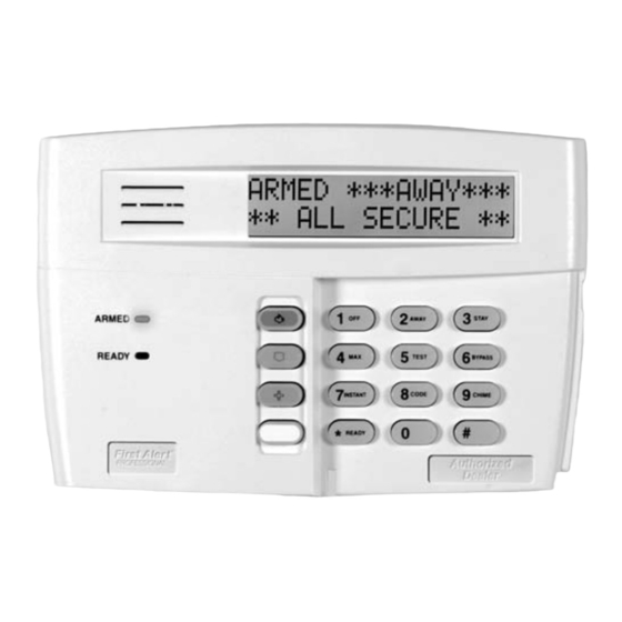
GENERAL INFORMATION
The FA570RF keypad/transceiver is a combination unit that
combines the functions of the following devices:
• FA570KP Alphanumeric Addressable Keypad
• 5881H RF Receiver
• 5800TM Transmitter Module
The FA570RF Keypad/Transceiver may be used on any
control panel that supports alphanumeric keypads and 5800
Series wireless devices.
FEATURES
• Supports wireless key transmitters (e.g., (5804) and bi-directional transmitters (e.g., 5804BDV, 5828/5828V).
• Supports wireless keys with high-security (encryption) capability (e.g., 5804E).
• Provides a nominal range of 200' for the RF transmitters (some transmitters have a shorter range).
• Supports RF jam detection when the receiver is enabled.
• Capable of sending status signals (Armed, Ready, etc.) to bi-directional units such as 5804BDV, and 5828/5828V.
• The FA570RF automatically times out the backlighting of all keypad keys.
U L
The following 5800 series transmitters are not intended for use in UL installations: 5802, 5804, 5804BD, 5804BDV,
5804E, 5814, 5816TEMP, 5819, 5819BRS, 5819WHS, 5828/5828V and 5850.
INSTALLING THE FA570RF
Locate the FA570RF in an area and at a height where it is
convenient for user operation. The FA570RF must be at least
ten feet from the control panel to ensure proper operation of
the RF receiver.
Mounting And Wiring
The FA570RF has terminal blocks for connection to power
and data wires. Removing the keypad's case back provides
access to the terminal blocks.
The FA570RF can be surface mounted directly to a drywall,
or to a single- or double-gang electrical box.
1. To remove the case back, insert a small screwdriver
blade at a downward angle into Slot 1 and twist (the
right side pops up). Insert the screwdriver blade at a
downward angle into Slot 2 and twist (the left side pops
up). Insert the screwdriver blade into right side narrow
Slot 3 and twist. Separate the case back from upper case.
Display
Special
Function
Keys
Case Back
Figure 1. Removing the Case Back
R
Installation and Setup Guide
Slot 3
Slot 1
Slot 2
Keypad/Transceiver
FUNCTION KEYS
(refer to Figure 1)
The A, B, and C keys are designed for use as "panic" keys
(e.g., fire, police, personal emergency, etc.) or other special
functions on certain control panels. The D key may be used
as a "macro" key or other special functions with control
panels that support this feature. This allows a single key to
execute a preprogrammed series of system functions (e.g.,
bypassing zones, arming, etc.)
The A, B, C, and D keys must be pressed and
held down for at least two seconds to activate
their programmed panic functions.
2. Route wiring from the control panel through the
large opening in the case back.
a. If surface wiring is being used, wiring may be routed
through the top or the bottom left-side breakout in
the case back. The breakouts must be punched out
using a screwdriver before mounting the case back.
b. If desired, wires may be strain-relieved to the wire tie
point on the inside of the case back with a tie wrap
(not supplied).
3. Mount the case back to a wall or electrical box.
4.
Use the wiring table on the next page when
connecting the keypad. Wire directly from the
keypad's terminal block to the terminal block on the
control's PC board. Wire functions are marked next to
terminals.
See
the
Instructions for more complete details.
Figure 2. FA570RF Wiring Details (back cover removed)
K14031 3/06 Rev. C
FA570RF
control
panel's
Installation
Y +
G
WIRING TERMINALS
(TO CONTROL PANEL)
Advertisement
Table of Contents

Subscribe to Our Youtube Channel
Related Manuals for First Alert FA570RF


Summary of Contents for First Alert FA570RF
- Page 1 2. Route wiring from the control panel through the large opening in the case back. Locate the FA570RF in an area and at a height where it is a. If surface wiring is being used, wiring may be routed convenient for user operation. The FA570RF must be at least...
- Page 2 1*48, and must match the partition assigned to the FA570RF. Wireless keys can be used on more than one partition, using a House ID programmed in the FA570RF and the devices. In this case, the wireless keys must be assigned to the same partition as the FA570RF.
- Page 3 DISABLING HIGH SECURITY DEVICES This mode gives you the ability to disable high security on all wireless keys that have been enrolled in the FA570RF. This is particularly useful if a user loses a wireless key.
- Page 4 TROUBLESHOOTING The error messages listed in the following table causes the FA570RF to produce a single ding tone. The table describes the error messages and the corrective actions. Display Probable Cause Corrective Action Low battery in the wireless key. Low Bat XXX (XXX = 1.
Need help?
Do you have a question about the FA570RF and is the answer not in the manual?
Questions and answers