Table of Contents
Advertisement
Quick Links
Advertisement
Table of Contents

Subscribe to Our Youtube Channel
Related Manuals for Lighthouse 1 CFM


Summary of Contents for Lighthouse 1 CFM
- Page 3 Lighthouse Worldwide Solutions 1 CFM Mini Manifold (TM) Operating Manual...
- Page 4 Copyright © 2008 by Lighthouse Worldwide Solutions. All rights reserved. No part of this document may be reproduced by any means except as permitted in writing by Lighthouse Worldwide Solutions. The information contained herein constitutes valuable trade secrets of Lighthouse Worldwide Solutions.
-
Page 5: Table Of Contents
Shipping Carton ......................1-1 Chapter 2 Introduction Overview ........................2-1 Description ........................2-1 Accessories ........................2-2 1 CFM Mini Manifold Specification ................2-2 Blower Specification ...................... 2-2 Chapter 3 Getting Started Initial Inspection ......................3-1 Routine Servicing ......................3-1 Features .......................... 3-2 Connections ........................ - Page 6 Lighthouse 1 CFM Mini Manifold Operating Manual GENERAL DEFINITIONS ..............4-2 Addressing ......................4-2 Communicating with the Instrument ................4-4 Computer Port ....................4-4 Sensor Port ......................4-5 RS-232 Communications ................... 4-5 RS-485 Communications ................... 4-6 Configuring with the MODBUS Protocol ..............4-8 Setting the Real Time Clock ................
- Page 7 Device Status ....................A-4 Command Register ....................... A-5 Alarm and Threshold Registers ..................A-6 Alarm Enable Registers ..................A-6 Enable Alarming for a Channel ............A-7 Threshold Setup Registers ................A-8 Setting the Alarm Threshold Value ............A-9 Sequence Registers ..................... A-10 Data Registers ......................
- Page 8 Lighthouse 1 CFM Mini Manifold Operating Manual t-iv 248083324-1 Rev 1...
-
Page 9: About This Manual
About this Manual This manual describes the detailed operation and use of the Lighthouse 1 CFM Mini Manifold. Text The following typefaces have the following meanings: Conventions italics Represents information not to be typed or interpreted literally. For example, file represents a file name. -
Page 10: Additional Help
Lighthouse 1 CFM Mini Manifold Operating Manual Additional For more information about the Lighthouse 1 CFM Mini Manifold, contact Lighthouse Worldwide Solutions: Help (800) 945-5905 Sales and Support (510) 438-0500 Outside of USA www.golighthouse.com techsupport@golighthouse.com 248083324-1 Rev 1... -
Page 11: Chapter 1 General Safety
General Safety These safety precautions pertain to the Lighthouse 1 CFM Mini Manifold. Safety The user or reader will find WARNINGS and CAUTIONS throughout Considerations this manual. Familiarize yourself with the meaning of a warning before proceeding. All warnings will appear in the left margin of the page next to the subject or step to which it applies. - Page 12 Lighthouse 1 CFM Mini Manifold Operating Manual 248083324-1 Rev 1...
-
Page 13: Chapter 2 Introduction
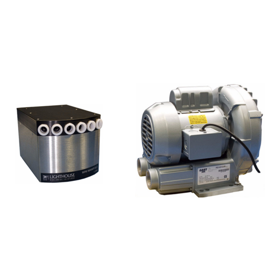
Introduction Overview This operating manual is an introduction to the Lighthouse Mini Manifold System. Description The Mini Manifold is an "air shield manifold" that uses a high-volume vacuum pump, or blower, to pull sample air through all of the sample tubes simultaneously. -
Page 14: Accessories
52 CFM (60Hz), 105 (50Hz) Blower Output 110VAC, 60 Hz, 5.6A maximum or Power Required 220VAC, 50 Hz, 9.3A maximum Weight 29 lbs/13.2 KG (60Hz) 61 lbs/27.7 KG (50Hz) Table 2-2 1 CFM Mini Manifold Blower Specifications 248083324-1 Rev 1... -
Page 15: Chapter 3 Getting Started
Shipping the instrument in other than factory approved packaging may subject it to shipping and handling damage and can void your warranty. If you need a shipping container, contact Lighthouse Customer Service and one will be provided for a nominal fee. Routine... -
Page 16: Features
Figure 3-1 Connections on back of Mini Manifold 1. RS-232/485 IN port and RS-485 OUT port: Communication ports. 2. RS-485 SENSOR Port: Connection port for SOLAIR 1 CFM Airborne Particle Counter. This connects to the SOLAIR RS-232/ 485 IN port 3. -
Page 17: Communication Ports
RS-485 to 232 converter, cables, connectors and terminator. Please connect OUT ports only to IN ports and use only contact your Lighthouse Sales Representative for the LWS RS-485 standard 8-wire CAT5 converter kit. cable. Do NOT connect 2... -
Page 18: Vacuum Pump/Blower
Manifold and SOLAIR system, refer to the LMS Express RT, RT+ or LMS Operating Manuals. Vacuum The 1 CFM Mini Manifold uses a Vacuum Pump (Blower) to supply a continuous vacuum to the Manifold, which keeps air flowing through Pump/Blower all ports and keeps them and the interior of the manifold free of particles. - Page 19 Getting Started The blower input tubing should be limited to ten feet as well as the exhaust tubing (if desired to ’port’ exhaust outside of blower location). Vibration dampening pads should be used if the blower will be installed where it may transmit vibrations into the particle counter; this will prevent spurious counts.
- Page 20 Lighthouse 1 CFM Mini Manifold Operating Manual 248083324-1 Rev 1...
-
Page 21: Chapter 4 Programming
Programming General The Mini Manifold can be programmed using the MODBUS Protocol. The full MODBUS protocol is detailed in Appendix A. Information This chapter contains the information needed to program the basic configuration of the instrument. DIP Switches The DIP switches are located behind a panel above the power connectors as shown in Figure 4-1. -
Page 22: Dip Switch Settings
Lighthouse 1 CFM Mini Manifold Operating Manual DIP Switch Settings GENERAL DEFINITIONS Position# Description Setting Binary Bit 0 OFF=0, ON=1; Default is ON (Address 1) Binary Bit 1 OFF=0, ON=1 Binary Bit 2 OFF=0, ON=1 Binary Bit 3 OFF=0, ON=1... - Page 23 Programming DIP SWITCHES DIP SWITCHES ADDRESS ADDRESS 1 2 3 4 5 6 1 2 3 4 5 6 0 1 1 0 0 0 0 1 1 0 0 1 1 1 1 0 0 0 1 1 1 0 0 1 0 0 0 1 0 0 0 0 0 1 0 1 1 0 0 1 0 0...
-
Page 24: Communicating With The Instrument
Lighthouse 1 CFM Mini Manifold Operating Manual Communicating The RJ-45 connector on the RS-232/485 IN port on the instrument is with the used to connect the unit to a COM port on a desktop or laptop PC. This Instrument connection can use RS-232 communications or RS-485 with an RS-485 to RS-232 converter. -
Page 25: Sensor Port
Programming The pinouts of the adapter are shown in the table below: RJ-45 Pin Signal Name DB-9 Pin TX > RX RX < TX Ground CTS < RTS Table 4-4 RJ-45 to DB-9 Connections Sensor Port WARNING: The Sensor port has the 2 lines for the RS-485 communications as well When daisy-chaining multiple as 24V to supply power to the REMOTE 2014P/3014P/5014P. - Page 26 In order to use the RS-485 protocol, an RS-485 converter must be used in a 2-wire configuration where ChB+ goes to RJ-45 pin 4, ChA- goes to RJ-45 pin 5. Lighthouse has an RS-485 converter kit that includes the cables, connectors and terminator needed to set this up. Please contact your Lighthouse Worldwide Solutions sales representative for this kit.
- Page 27 Programming Note: To connect the instrument to a computer using RS-485 Protocol, refer When Daisy chaining, make sure that to the instructions below and Figure 4-4. each instrument has a unique COMM address. 1. Remove power from the instrument. 2. Connect an RJ-45 cable to the RS-232/485 IN port of the instrument.
-
Page 28: Setting The Real Time Clock
Lighthouse 1 CFM Mini Manifold Operating Manual Configuring The instrument is configured using the MODBUS protocol. with the Setting the Real Time Clock MODBUS Protocol The Real Time Clock (RTC) can be read in registers 40027 and 40028: Register Data Type... - Page 29 Programming • PURGE Time The amount of time the controller will purge the tubing between counts from a given locations. • SAMPLE Time The time in seconds that the sensor is actively counting particles. • HOLD Time The amount of time the sample tube holds before moving to the next port location.
-
Page 30: Running The Instrument
Lighthouse 1 CFM Mini Manifold Operating Manual Running the The instrument can be run in a few different ways. The applicable action commands are discussed in Table 4-9: Instrument Value Action Saves all writable 4xxxx register values to the EEPROM. - Page 31 Programming WARNING: Do not assign 0 to register 46001 - the Mini Manifold Register Value will not collect data with this setting. 46001 46002 46003 46004 46005 46006 46007 Table 7: Sample Sequence An example sequence is shown above where it starts with port 1, followed with port 3, 5, 4, 2 and 6.
- Page 32 Lighthouse 1 CFM Mini Manifold Operating Manual 4-12 248083324-1 Rev 1...
-
Page 33: Chapter 5 Final System Setup And Checks
From a system level, a typical installation of a Manifold involves a Mini Manifold ("Manifold"), vacuum pump ("blower" or "pump") and a particle counter ("Sensor", typically a SOLAIR 1 CFM). The Manifold programs the Sensor’s sampling functions and communicates with external computers for data collection. This chapter will provide the steps to get the Manifold connected to and working with the Sensor and an external computer. -
Page 34: Connecting The System Components
Lighthouse supplies adapters for connecting to the Manifold System and Sensor, individually. If you are unsure about which adapter to use or how to connect it, contact Lighthouse Sales, Technical Support or Customer Service before proceeding. The adapter used will dictate... -
Page 35: Computer Rs-485 Out Port
Final System Setup and Checks Computer RS-485 OUT Port This port allows daisy chaining of Manifolds, uses standard Cat5 cabling and must be connected to the next Manifold’s RS-232/485 IN port. The last Manifold in line must be terminated. WARNING: Do NOT connect the IN port to another IN port. -
Page 36: Connections
Lighthouse 1 CFM Mini Manifold Operating Manual RJ-45 Pin Signal Name RS485B RS485A 24VDC Ground Table 5-2 Sensor Port Pinouts Connections: Sensor to Manifold Remove AC power from ALL instruments before making new or changing current connections. Note: Connect the Manifold to the Sensor by connecting a Cat5e cable The word "Sensor"... -
Page 37: Communication Test
1. Management System By uploading the data into the Lighthouse Monitoring System (LMS) or into LMS Express RT or RT+, you can store historical data for future review and trending. Please refer to the LMS or LMS Express RT, RT+ manuals for further information about these systems. -
Page 38: Rs232 Communications
50 feet from a computer or monitoring system. For a PC computer to use the RS485 protocol, an RS232/485 converter must be used. Lighthouse has an RS485 converter kit that includes the cables and connectors to set this up. Please contact a Lighthouse Worldwide Solutions Sales Representative for this kit. -
Page 39: Lms Express Rt Starting Set Up
Final System Setup and Checks LMS Express RT Starting Set Up Use the LMS software to add the manifold (Add Instrument - Fig- ure 5-2). If service indicators appear for the manifold or sensor (see specific operating manual for software being used for Status Symbols), recheck the connections. - Page 40 Lighthouse 1 CFM Mini Manifold Operating Manual Note: Make sure that the Manifold and Sensor COMM addresses In order for the Manifold to communicate match. Refer to “DIP Switches” on page 3, for instructions on with a Particle Counter, the setting instrument address.
-
Page 41: Chapter 6 Maintenance
Purge Test The SOLAIR 1 CFM particle counters are shipped with a 0.1μm, 1 CFM purge filter. Whenever counts appear to be unreliable or when Lighthouse technical support recommends its use, a purge test can be performed on the counter. - Page 42 Lighthouse 1 CFM Mini Manifold Operating Manual 248083324-1 Rev 1...
-
Page 43: Appendix A Modbus Register Map V1.39
MODBUS Register Map v1.39 COMM Lighthouse particle counters with MODBUS have the following communication settings: Settings 19200 Baud Rate Data Bits Stop Bits Parity None Hardware Protocol RS-232C or RS-485 Standard Software Protocol MODBUS ASCII (supports upper/lower case) Table A-1 MODBUS Communications Settings The MODBUS slave address is set on the particle counter. -
Page 44: Register Map
Lighthouse 1 CFM Mini Manifold Operating Manual Register Map Sensor Settings Registers Instrument settings are stored in holding registers (the 4xxxx series), which are mostly read/write-able. Not all holding registers are writable. Table A-2 describes the content of these registers. - Page 45 ASCII string Model Name char[14], char [15] 40023 unsigned integer Flow Rate. Divide by 100 to get rate in CFM. For example, 100 = 1 CFM. 40024 signed integer Record Count. Total number of records stored in the counter. 40025 signed integer Record Index.
-
Page 46: Device Status
Lighthouse 1 CFM Mini Manifold Operating Manual Register Data Type Description 40035 unsigned integer Data Set [high]. Works in conjunction with 40036. Updates the instrument’s real time clock. Setting is the number of seconds since midnight, 1/1/1970. Data entered here is applied to the device through the command register. -
Page 47: Command Register
MODBUS Register Map v1.39 Command The Command Register (40002) is used to make the device perform an action. The register performs an action when an integer value is written Register to it. The action is completed when the device sends a MODBUS response. -
Page 48: Alarm And Threshold Registers
Lighthouse 1 CFM Mini Manifold Operating Manual Value Action Set Real Time Clock. Writes "Data Set" values (from Registers 40035 & 40036) to the local Real Time Clock. New time value is saved. Table A-5 Command Register Alarm and Alarm Enable Registers Threshold The Alarm Enable input registers (43xxx series) are read/write. -
Page 49: Enable Alarming For A Channel
MODBUS Register Map v1.39 Register Data Type Description 43010 unsigned int Alarm Enable for Particle Channel 1 [low] 43011 unsigned int Alarm Enable for Particle Channel 2 [high] 43012 unsigned int Alarm Enable for Particle Channel 2 [low] 43013 unsigned int Alarm Enable for Particle Channel 3 [high] 43014 unsigned int... -
Page 50: Threshold Setup Registers
Lighthouse 1 CFM Mini Manifold Operating Manual Particle Bit 1 Registers Channel Enabled 43011 - 43012 43013 - 43014 43015 - 43016 43017 - 43018 43019 - 43020 43021 - 43022 43023 - 43024 Table 8: Example of Alarming on Channel 2 Use the Threshold registers to set the alarm threshold value. -
Page 51: Setting The Alarm Threshold Value
MODBUS Register Map v1.39 Register Data Type Description 45011 unsigned int Threshold for Particle Channel 2 [high] 45012 unsigned int Threshold for Particle Channel 2 [low] 45013 unsigned int Threshold for Particle Channel 3 [high] 45014 unsigned int Threshold for Particle Channel 3 [low] 45015 unsigned int Threshold for Particle Channel 4 [high]... -
Page 52: Sequence Registers
Lighthouse 1 CFM Mini Manifold Operating Manual Particle Threshold Registers Channel Value 45019 - 45020 1000 45021 - 45022 1000 45023 - 45024 1000 Table 9: Alarm Threshold Registers set to 1000 Sequence Sequence registers are used to position the sampling mechanism. - Page 53 MODBUS Register Map v1.39 recently saved value is at Index=-1. Register Data Type Description 30001 signed integer Timestamp [high] (# of seconds since midnight, 1/1/1970) 30002 signed integer Timestamp [low] 30003 unsigned integer Sample Time [high] (In seconds) 30004 unsigned integer Sample Time [low] 30005 signed integer...
- Page 54 Lighthouse 1 CFM Mini Manifold Operating Manual Register Data Type Description 30042 IEEE Float Analog Channel 1 [low] 30043 IEEE Float Analog Channel 2 [high] 30044 IEEE Float Analog Channel 2 [low] 30045 IEEE Float Analog Channel 3 [high] 30046...
-
Page 55: Device Status Word
The bit order of the Device Status Word is 7 to 0 (right to left), where Lighthouse instruments bit 7 is the most significant bit and bit 0 is the least significant bit. only use the first (least significant) byte. -
Page 56: Data Enable Registers
Lighthouse 1 CFM Mini Manifold Operating Manual Description Laser Alert Status 0 = Laser is good 1 = Laser Alert Flow Alert Status 0 = Flow Rate is good 1 = Flow Rate Alert Particle Overflow Status 0 = No overflow... -
Page 57: Data Units Registers
MODBUS Register Map v1.39 four characters will not end with a NULL character. String Description TIME Timestamp STIM Sample Time SVOL Sample Volume Location STAT Status TEMP Temperature Relative Humidity AIRV Air Velocity DPRS Differential Pressure Electrostatic Discharge FLOW Flow Rate LASV Laser Voltage VOLT... - Page 58 Lighthouse 1 CFM Mini Manifold Operating Manual 30xxx series. The Units Registers run in parallel with the Data Registers. For example, Data Register 30010’s Units Register is 42010. Note: Units are stored as 4 character ASCII strings across 2 registers. If the Not all data types have units.
- Page 59 MODBUS Register Map v1.39 Units Description Units Description p/m3 Particles per cubic meter Table A-13 Data Units 248083324-1 Rev 1 A-17...
- Page 60 Lighthouse 1 CFM Mini Manifold Operating Manual A-18 248083324-1 Rev 1...
-
Page 61: Appendix B Troubleshooting
Troubleshooting Overview This chapter provides a troubleshooting guide for the 1 CFM Mini Manifold. The scope of this chapter is to address issues involving these two components and addresses Manifold system balancing. Due to the complexity of the total system, a system-level approach to diagnosis is required, steps of which should be performed on-site. -
Page 62: System Balancing
Lighthouse 1 CFM Mini Manifold Operating Manual System Balancing a particle sampling system such as the Lighthouse Mini Manifold System requires good planning and proper implementation of Balancing the sample tube network. It also requires proper handling and setup of the components. -
Page 63: Preliminary Checks
Use the Lighthouse Air Flow Balance Unit (AFBU) to measure the flow rate through each of the two test sample tubes. The flow rate shown is correct for the system. The AFBU is designed to be used with the Lighthouse manifold systems. -
Page 64: Successful Flow Check
Contact Lighthouse for the availability of this option. If the longest run is reading too low and the blower is adjusted to its maximum output, verify the installation by duplicating the run and attaching to the same port. -
Page 65: Appendix C Limited Warranty
Upon expiration of the initial two-year warranty, all parts and any way altered without the explicit written consent of LWS then repairs completed by an authorized Lighthouse repair technician the warranty is null and void. This warranty is limited to a period are subject to a six (6) month warranty. - Page 66 Lighthouse 1 CFM Mini Manifold Operating Manual 248083324-1 Rev 1...
-
Page 67: Index
Index Connections 3-2 Communication ports 3-2 Power 3-2 Accessories 2-2 Count Modes 2-2 Additional help ii Addressing 4-2 AFBU B-3 Air Flow Balance Unit B-3 Alarm Enable Registers A-6 Data 3-3 Alarm Registers Data Enable Registers A-14 Enable Alarming A-7 Data Registers Automatic Mode 4-10 Device Status Word A-13... - Page 68 Lighthouse 1 CFM Mini Manifold Operating Manual Power Requirements 5-1 Programming 4-1 DIP Switches 4-2 Help ii Purge filter 6-1 Purge Test 6-1 Initial Inspection 3-1 Installation Real Time Clock Connecting power 5-1 Setting 4-8 Connecting to computer 5-5 Real-time system 3-4...
- Page 69 Index Threshold Setup Registers A-8 Setting the Alarm Threshold Value A-9 Troubleshooting Installation B-2 Manifold B-1 Tubing Installation Installation Parameters B-2 Uninterruptible Power Supply 5-1 User-serviceable parts 1-1 Warning Infrared Radiation 1-1 WARNINGS and CAUTIONS 1-1 Warranty 1-1, 6-1 Weight 2-2 248083324-1 Rev 1...
- Page 70 Lighthouse 1 CFM Mini Manifold Operating Manual 248083324-1 Rev 1...
Need help?
Do you have a question about the 1 CFM and is the answer not in the manual?
Questions and answers