Table of Contents
Advertisement
Quick Links
Advertisement
Table of Contents

Subscribe to Our Youtube Channel
Related Manuals for IFM O3M ZZ1103

Summary of Contents for IFM O3M ZZ1103
- Page 1 Instructions for set-up Area surveillance ZZ1103...
-
Page 2: Table Of Contents
O3M area surveillance Contents 1 Preliminary note � � � � � � � � � � � � � � � � � � � � � � � � � � � � � � � � � � � � � � � � � � � � � � � � � � � � � � � � � � � � � � � � � � � �3 1�1 Symbols used �... -
Page 3: Preliminary Note
Death or serious irreversible injuries may result� CAUTION Warning of personal injury� Slight reversible injuries may result� NOTE Warning of damage to property 1.3 Further documents ● Quick reference guide ● Operating instructions ● Software manual Download the documents at → www.ifm.com... -
Page 4: Safety Instructions
O3M area surveillance 2 Safety instructions ● The devices described are integrated into a system as components� – The operator is responsible for the safety of the system� – The system architect undertakes to perform a risk assessment and to create documentation in accordance with legal and normative requirements to be provided to the operator and user of the system�... -
Page 5: 2�2 Safety Note E2M Monitor
The following areas of a vehicle can be monitored: ● Front ● Rear ● Sides The ZZ1103 O3M area surveillance set does not relieve the driver of his responsibility to operate the vehicle safely� More information: www�ifm�com and mobilevision@ifm�com... -
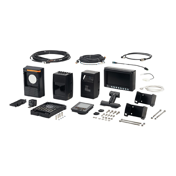
Page 6: Items Supplied
O3M area surveillance 4 Items supplied Number Article number Description Photo O3M261 Mobile 3D sensor with integrated 2D/3D overlay (pre- programmed) Angle of aperture 3D: 95°x32° O3M960 IR illumination unit for O3M261 E3M102 Mounting bracket for 3D sensor and illumination unit, stainless steel, black E3M120 MCI connection cable for 3D sensor and illumination... - Page 7 O3M area surveillance Number Article number Description Photo 80281057 Buzzer 24 V for connection to CR0403 Depending on the operating voltage, use the buzzer for 12 V or 24 V� 80303178 Buzzer 12 V for connection to CR0403 Depending on the operating voltage, use the buzzer for 12 V or 24 V�...
- Page 8 O3M area surveillance Number Article number Description Photo E2M239 Bracket for monitor E2M231 E2M203 Connection cable for analogue video signal, M16 connector to M16 socket, 5 m, black, PVC E3M161 Analogue video adapter cable, M12 connector to M16 connector, for the connection of O3M261 to E2M203, 1 m, black...
-
Page 9: Getting Started
O3M area surveillance 5 Getting started The chapter "Getting started" provides a brief description of the installation, the electrical connection and the set-up� Fig� 2: Connected devices of the ZZ1103 set E3M171 CR0451 System läuft CAN Adapter cable und ist verfügbar 12/24 V Basi c Di s pl a y E3M133... -
Page 10: 5�1 Connection Overview
O3M area surveillance 5.1 Connection overview The table contains the electrical connection of the devices. The column "Connection" contains the connections of the devices. The column "Connection target" contains the target of the respective connection� The devices can be connected to 12 V or 24 V on-board systems� Article Photo Wiring... - Page 11 O3M area surveillance Article Photo Wiring Connection Connection target E3M120 Angled → O3M261 Not angled → O3M960 E3M133 M12 socket → O3M960 Wires, brown → U+ (9...32 V DC) Wires, blue → GND E3M172 Terminal block → ② CR0403 ② Wire, white →...
-
Page 12: 5�2 Mounting
O3M area surveillance Article Photo Wiring Connection Connection target E2M203 M16 connector → E2M231, video input M16 socket → E3M161, M16 connector E3M161 M16 connector → E2M203, M16 socket M12 connector → ④ O3M261, M12 socket 5.2 Mounting ► Connect the devices as shown in Fig� 3� ►... - Page 13 O3M area surveillance Fig� 4 : Schematic representation of the 3D field of view of a mounted 3D sensor Fig. 5 shows the 3D sensor with illumination unit mounted on an excavator. The letters "h" and"α" are assigned to values from the previous table� Fig�...
-
Page 14: 5�3 Setting The Area Surveillance
O3M area surveillance 5.3 Setting the area surveillance The area surveillance is divided into 3 zones� The zones represent risk levels, with the [ ] zone representing the lowest risk level and the [ ] zone representing the highest risk level� The size of the zones can be adjusted for different vehicles and scenarios�... - Page 15 O3M area surveillance Calibration Automatic calibration The measured height and The automatic calibration is trying to determine the inclination angle inclination angle of the 3D sensor and height of the 3D sensor� are entered manually� For automatic calibration, the 3D sensor must have a clear view The values must be measured of the ground (approx.
- Page 16 O3M area surveillance Zone definition Zone definition - zones Via the zone definition, the width The width and length of the zones can be set� The same value is and length of the zones can set for the left and right areas of the zone� Adding the left and right be set�...
-
Page 17: Function
O3M area surveillance 6 Function The devices included in the ZZ1103 set make up an assistance system that supports the surveillance of hazardous areas� A hazardous area can be, for example, the blind spot of mobile machines� 6.1 Mobile 3D smart sensor The mobile 3D smart sensor is approved for operation on mobile machines�... -
Page 18: Mounting
O3M area surveillance 7 Mounting 7.1 Mounting the BasicController NOTE The BasicController and the BasicDisplay can be damaged when installed in engines� ► Install the BasicController and the BasicDisplay in vehicle bodies� ① ① ► Mount the BasicController to a suitable surface using ①... - Page 19 O3M area surveillance The table contains exemplary values for various mounting positions (depending on the mounting location, taking into account a minimum distance A in front of the 3D sensor). Mounting height Recommended Min� Max� Width at the Width at the end of h [m] inclination angle distance A...
-
Page 20: 7�3 Measuring The Inclination Angle And Height Of The 3D Sensor
O3M area surveillance 7.3 Measuring the inclination angle and height of the 3D sensor The 3D sensor must be calibrated before it can be used� The inclination angle and the height of the 3D sensor are required for calibration� The inclination angle and the height refer to the world coordinate system� Both values are required for set-up (→... -
Page 21: 7�4 Example Of Mounting The 3D Sensor On The Vehicle Rear
O3M area surveillance 7.4 Example of mounting the 3D sensor on the vehicle rear Fig� 1 shows the 3D sensor mounted centrally on a vehicle with the illumination unit mounted directly next to it. The letters "A-D" are assigned to values from the previous table (→ "7.2 Mounting the 3D sensor and illumination unit"). -
Page 22: Electrical Connection
► Firmly screw the M12 connectors to the unit� Cover the unused sockets with the pre-mounted protective caps� Tightening torque 0�8 Nm� The devices can be connected to 12 V or 24 V on-board systems� Available accessories: www�ifm�com Fig� 12: Connected devices of the ZZ1103 set... - Page 23 O3M area surveillance E3M171 CR0451 System läuft CAN Adapter cable und ist verfügbar 12/24 V Basi c Di s pl a y E3M133 Connection cable E3M171 CAN Adapter cable CR0403 O3M261 O3M960 E3M171 BasicController Illumination 3D sensor CAN Adapter cable unit E3M161 E3M120...
-
Page 24: 8�1 Wiring 3D Sensor
Fig� 15: Wiring 3D sensor, bottom 8.2 Wiring illumination unit ① MCI - Modulation and Communication Interface Connection sensor - illumination unit Only use original ifm cables E3M120, E3M121, E3M122 or E3M123� ② Power supply M12 connector, A-coded, 4 poles 9���32 V DC 9���32 V DC... -
Page 25: 8�3 Wiring Basiccontroller
O3M area surveillance 8.3 Wiring BasicController The supply cables, CAN interfaces and input/outputs are connected via 6�3 x 0�8 mm blade male terminals on the front of the BasicController� The BasicController contains an application-specific configuration (the area surveillance application package). Depending on the configuration, only certain inputs are available. ①... -
Page 26: 8�4 Wiring E2M Monitor
O3M area surveillance The outputs of the BasicController (blocks D, E and F) can be used as input signals for engine controllers or similar� Block F is reserved� 8.4 Wiring E2M monitor ① Power supply 7 wires, open ends U+ (12...32 V DC) white CAUTION Malfunction... - Page 27 O3M area surveillance 2� Connect the connector for the buzzer ② (E3M172) to "Block F". > The connector (E3M172) is only required if the buzzer is used� ② 3� Connect the white wire of E3M172 to terminal 30 of the buzzer� 4�...
- Page 28 O3M area surveillance ⑧ 9� Pull out the locking lever ⑩ rotate it towards you� ⑧ 10� Feed the remaining lines of the E3M171 CAN adapter cable through the rubber lip of the cover to the outside� ⑦ 11� Insert the cover guides into ⑥...
-
Page 29: 8�6 Connecting The 3D Sensor And Illumination Unit
O3M area surveillance 8.6 Connecting the 3D sensor and illumination unit 1� Connect the M12 socket of the long side of the E3M171 CAN adapter cable ① to the M12 connector of the 3D sensor � 2� Connect the blue and brown wires of the E3M171 to a power supply: blue: GND, brown: L+ (9...32 V DC). -
Page 30: Operating And Display Elements
O3M area surveillance 9 Operating and display elements If an object is detected within the monitored area: ● The output of the BasicController changes depending on the distance to the detected object� ● The background and text colour of the BasicDisplay change� ●... -
Page 31: Set
O3M area surveillance 10 Set-up Before set-up, the area surveillance is set (→ "10.1.3 Configuration wizard"). The following parameters of the 3D sensor and the vehicle are necessary for set-up: ● inclination angle of the 3D sensor ● height of the 3D sensor (→ "7.3 Measuring the inclination angle and height of the 3D sensor") ●... -
Page 32: 10�1�1 Start Screen And Operating Status
O3M area surveillance 10.1.1 Start screen and operating status Start screen Operating status Device information The start screen is displayed The system status shows the The device information shows when the system is started� operating status of the devices (→ information about the individual "11.2 Operating states"). -
Page 33: 10�1�2 Expert Settings
O3M area surveillance 10.1.2 Expert settings Expert settings for the display The expert settings contain settings for the BasicDisplay under the [Display] tab: 1� [Password settings]: Activate password protection for the area surveillance settings� The password is requested once per operating cycle (time between switching on and off). The password "000" deactivates the password protection�... - Page 34 O3M area surveillance Expert settings for I/O modules The expert settings contain settings for the BasicController under the [I/O-Module] tab: 1� [Acoustic warning]: Adjust the volume of the buzzer� Possible settings: – [Off] – [100% volume] – [75% volume] – [50% volume] 2�...
- Page 35 O3M area surveillance Expert settings for the 3D sensor In standby mode ● the configuration wizard is not available, ● the settings of the 3D sensor cannot be changed� The expert settings contain settings for the 3D sensor under the [3D sensor] tab: 1�...
- Page 36 – [Output 2D video on] – [Mirror video off] – [Mirror video on (rear view)] 8� [Visualisation configuration]: Switch the display of the ifm logo in the 2D image on or off� Possible settings: – [ifm logo not visible] – [ifm logo visible] Recommended settings for different vehicle types: (→...
-
Page 37: 10�1�3 Configuration Wizard
O3M area surveillance 10.1.3 Configuration wizard Configuration wizard Password protection The configuration wizard guides Activate password protection for you step by step through the area surveillance settings� the configuration of the area The password is requested surveillance� once per operating cycle (time between switching on and off). - Page 38 O3M area surveillance Calibration The 3D sensor must be calibrated before it can be used� The inclination angle and the height of the 3D sensor are required for calibration (→ "7.3 Measuring the inclination angle and height of the 3D sensor"). The calibration consists of two steps: 1�...
- Page 39 O3M area surveillance Object detection type Zone definition The object detection type determines The zone definition determines how the zone widths are set: how objects are treated: ● [Quick setup]: The same value is set for the left and right ●...
-
Page 40: 10�1�4 Zone Definition - Default Settings
O3M area surveillance 10.1.4 Zone defi nition - default settings Zone definition Zone definition - zones Via the zone definition, the width The width and length of the zones can be set� The same value is and length of the zones can set for the left and right areas of the zone�... -
Page 41: 10�1�5 Zone Definition - Expert Settings
O3M area surveillance Zone definition - transfer of values The values are transferred to the 3D sensor� Then the 3D sensor is restarted� The 3D sensor is not available during this restart� If the buzzer beeps after restarting the 3D sensor: ►... - Page 42 O3M area surveillance Zone definition - zones Zone definition - zones Save the set zone values� The width and length of the zones can be set� The left and right After saving, the system is areas of the zone are set separately� restarted and the display is in the monitoring mode (→...
-
Page 43: 10�2 Monitoring Mode
O3M area surveillance 10.2 Monitoring mode After set-up, a function test must be carried out� ► Drive towards an object at typical speed and check the reaction of the system� Once the area surveillance has been set, the system is ready for operation and runs in monitoring mode� The readiness for operation of the system is signalled by the live ticker�... -
Page 44: Troubleshooting
O3M area surveillance 11 Troubleshooting 11.1 Status LED The status LED of the BasicDisplay indicates the operating states of the system� The status LED of the BasicDisplay is synchronised with the status LED of the BasicController� Both show the same states� BasicController / 3D sensor: initialisation 250 ms 250 ms... -
Page 45: 11�2 Operating States
O3M area surveillance 11.2 Operating states The system status shows the operating states of the BasicDisplay, BasicController and 3D sensor (→ "10.1.2 Expert settings"). Fig� 21: Indication of the operating states The following operating states are indicated: Display Operating status NORMAL The device is connected and compatible�... - Page 46 The 3D sensor signals an error and must be restarted� ► Restart the 3D sensor� The 3D sensor signals an error� The error can be read via the ifm Vision Assistant software� ► Read the error via the ifm Vision Assistant�...
-
Page 47: 11�4 Error Codes 3D Sensor
Internal fault O3M function limited (unavailable) Blockage detected O3M function limited (unavailable) Availability != 0 ► Contact ifm support O3M function limited (unavailable) The O3M is not available, availability = 255 ► Contact ifm support O3M function limited (unavailable) Returning to standard Run mode from limited Run mode 97��110... -
Page 48: 11�5 Error Codes Basiccontroller
► Contact ifm support Device error The O3M device information cannot be read� UDS blocked by another member (e�g� ifm Vision Assistant). Device error Unable to assign an address to the device, no device information available�... -
Page 49: Terms And Abbreviations
O3M area surveillance 12 Terms and abbreviations Term Description The region of interest defines the area to be monitored� The field of view describes the area covered by the angle of aperture of the 3D sensor� 13 Frequently asked questions Problem Solution False triggering during... - Page 50 O3M area surveillance Problem Solution The ZZ1103 set The ZZ1103 set is used as a reversing assistance system and should only be should only be active active when reverse gear is engaged� when reverse gear is ► Set the ZZ1103 set to standby mode via the digital input IN11 of the engaged�...
- Page 51 O3M area surveillance Problem Solution Setting up and After successful set-up, the ZZ1103 set can be operated without BasicDisplay� operating several The configuration is saved on the BasicDisplay and can be transferred to other vehicles and ZZ1103 ZZ1103 sets� sets with one ►...
-
Page 52: Accessories
O3M area surveillance 14 Accessories The following articles are used as alternatives or in addition to the articles included in the ZZ1103 set� Article number Description Photo O3M151 Mobile 3D sensor without integrated 2D sensor For use without 2D monitor Angle of aperture 3D: 70°x23°... - Page 53 O3M area surveillance Article number Description Photo E3M103 Mounting set for clamp mounting For mounting on a rod Compatible with 3D sensor and illumination unit E3M131 Connection cable for illumination unit, length 2 m E3M132 Connection cable for illumination unit, length 5 m EC0401 Cover for BasicController if the BasicDisplay is not used E2M202...
Need help?
Do you have a question about the O3M ZZ1103 and is the answer not in the manual?
Questions and answers