Table of Contents
Advertisement
Quick Links
Advertisement
Table of Contents
Troubleshooting

Related Manuals for protech ProX-1670

Summary of Contents for protech ProX-1670
- Page 1 USER’S MANUAL ProX-1670 For Socket 370 Embedded Board With VGA / SOUND / 2LAN...
- Page 2 Copyright Notice ProX-1670 Socket 370 Embedded Board With VGA / SOUND / Dual LAN OPERATION MANUAL COPYRIGHT NOTICE This operation manual is meant to assist both Embedded Computer manu- facturers and end-users in installing and setting up the system. The infor- mation contained in this document is subject to change without any prior notice.
-
Page 3: Table Of Contents
Contents TABLE OF CONTENTS CHAPTER 1 INTRODUCTION About This Manual ............System Specifications ........... Safety Precautions ............CHAPTER 2 HARDWARE CONFIGURATION Jumper & Connector Quick Reference Table ....Component Locations ........... How to Set the Jumpers ..........COM Port Connector ............ RS232/422/485 (COM2) Selection ....... - Page 4 Contents 2-30 Green Function Connector …..……………………….. 2-26 2-31 IrDA Connector ……………………………………..2-26 2-32 LAN Led Indicator ............2-27 2-33 ATX Power Switch Connector …………………….…. 2-27 2-34 LAN Wake-Up Connector …………………………… 2-28 2-35 Memory Installation ............2-28 2-36 Sound Enable/Disable Selection ……………………... 2-28 2-37 LAN Enable/Disable Selection ……………………….
- Page 5 Contents 5-12 IDE HDD Auto Detection ..........5-27 5-13 Save & Exit Setup ............5-28 5-14 Exit Without Saving ............5-29 APPENDIX A ADAPTER CARD W-Sound Adapter Card ............….. APPENDIX B EXPANSION BUS PISA Bus Pin Assignment ............APPENDIX C TECHNICAL SUMMARY Block Diagram .................
-
Page 6: Chapter 1 Introduction
CHAPTER INTRODUCTION This chapter gives you the information for Prox-1670. It also outlines the System specifications. Section includes: About This Manual System Specifications Safety precautions Experienced users can skip to chapter 2 on page 2-1 for a Quick Start. Page:1-1... -
Page 7: About This Manual
Chapter 1 Introduction 1-1. ABOUT THIS MANUAL Thank you for purchasing our Prox-1670 Socket 370 Embedded Board with VGA/Sound/LAN, which is fully PC / AT compatible. The Prox-1670 provides faster processing speed, greater expandability and can handle more tasks than before. This manual is designed to assist you how to install and set up the system. -
Page 8: System Specifications
5-pin PC/At keyboard connector with mini DIN cable. MOUSE CONNECTOR : PS/2 mouse connector with min DIN cable. BUS SUPPORT : Internal PCI Bus for VGA, LAN, Sound, & IDE. One PISA slot. One PPCI connector. Prox-1670 USER ′ S MANUAL Page: 1-3... - Page 9 Universal Serial Bus Connector, supports up to two USB ports. LAN ADAPTER : Dual port, Intel® 82559 PCI Fast Ethernet 10/100 Base-T PCI-BUS INFRARED FUNCTION : One Infrared port. Support IrDA v1.0 SIR protocol. Prox-1670 USER ′ S MANUAL Page: 1-4...
- Page 10 Hardware support by switch control. HARDWARE MONITORING FUNCTION : Monitor CPU Voltage, CPU temperature, and Cooling Fan. LED INDICATOR : System power. Hard Disk access. LAN LED indicators. DMA CONTROLLER : 82C37 x 2 DMA CHANNELS : Prox-1670 USER ′ S MANUAL Page: 1-5...
-
Page 11: Safety Precautions
3. Disconnect power when you change any hardware devices. For instance, when you connect a jumper or install any cards, a surge of power may damage the electronic components or the whole system. Prox-1670 USER ′ S MANUAL Page: 1-6... -
Page 12: Chapter 2 Hardware Configuration
CHAPTER HARDWARE CONFIGURATION ** QUICK START ** Helpful information describes the jumper & connector settings, and component locations. This section includes: Jumper & Connector Quick Reference Table Component Locations Configuration and Jumper settings Connector‘s Pin Assignments Page 2-1... -
Page 13: Jumper & Connector Quick Reference Table
LD1&2, LD3&4 ATX Power Switch Connector ………………….. JP12 (3,4) LAN Wake-up Connector ……………………….. JP16 DIMM1 Memory Installation ..........JP19 Sound Enabled/Disabled Selection ….…………... LAN Enable/Disable Selection ……….…………. Reserved pin ……………………………………... JP3, JP6, JP2 ’ Page: 2-2 Prox-1670 USER S MANUAL... -
Page 14: Component Locations
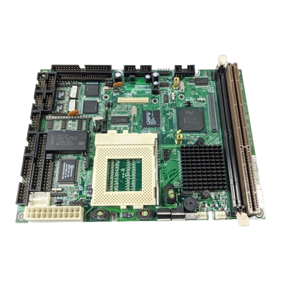
Chapter 2 Hardware Configuration 2-2. COMPONENT LOCATIONS PPCI DIMM 1 PISA Prox-1670 Connector, Jumper and Component locations ’ Page: 2-3 Prox-1670 USER S MANUAL... -
Page 15: How To Set The Jumpers
PIN2 & PIN3 to create another setting. The same jumper diagrams are applied all through this manual. The figure below shows what the manual diagram looks like and what they represent. ’ Page: 2-4 Prox-1670 USER S MANUAL... - Page 16 Chapter 2 Hardware Configuration JUMPER DIAGRAMS JUMPER SETTINGS ’ Page: 2-5 Prox-1670 USER S MANUAL...
-
Page 17: Com Port Connector
COM1 : COM1 Connector The COM1 Connector assignments are as follows : ASSIGNMENT COM1 COM2 : COM2 Connector The COM2 Connector assignments are as follows : ASSIGNMENT COM2 RS-232 RS-422 RS-485 RTS- RTS+ CTS+ CTS- ’ Page: 2-6 Prox-1670 USER S MANUAL... - Page 18 Chapter 2 Hardware Configuration COM3 : COM3 Connector The pin assignments are as follows : ASSIGNMENT COM3 COM4 : COM4 Connector The pin assignments are as follows : ASSIGNMENT COM4 ’ Page: 2-7 Prox-1670 USER S MANUAL...
-
Page 19: Rs232/422/485 (Com2) Selection
JP17 JP18 JP17 JP18 JP17 JP18 Function Open Open Open Jumper 9-10 9-10 setting 11-12 11-12 (pin closed) 13-14 13-14 15-16 15-16 17-18 17-18 19-20 19-20 Jumper illustration *** Manufactory default --- RS-232. ’ Page: 2-8 Prox-1670 USER S MANUAL... - Page 20 Chapter 2 Hardware Configuration 2-6. SOLID-STATE DISK SOCKET SSD : 32-pin Disk-on-chip Socket The pin assignments are as follows: ASSIGNMENT ASSIGNMENT SA12 SA10 SA11 ’ Page: 2-9 Prox-1670 USER S MANUAL...
-
Page 21: Ssd Memory Mapping Selection
The SSD Memory Mapping Selections are as follows: JUMPER SETTINGS JUMPER SSD Memory Map (pins closed) ILLUSTRATION CC000h-CDFFFh 11-12 D0000h-D1FFFh 9-10 D4000h-D5FFFh 11-12 D8000h-D9FFFh 9-10 DC000h-DDFFFh 11-12 E0000h-E1FFFh 9-10 *** Manufactory default --- CC000h-CDFFFh ’ Page: 2-10 Prox-1670 USER S MANUAL... -
Page 22: Keyboard Connector
KB1 : PC/AT Keyboard Connector The jumper settings are as follows: ASSIGNMENT KCLK KDATA IOVSB 2-9. PS/2 MOUSE CONNECTOR MS1 : PS/2 Mouse Connector The pin assignments are as follows : ASSIGNMENT MCLK MDATA IOVSB ’ Page: 2-11 Prox-1670 USER S MANUAL... -
Page 23: Reset Connector
ASSIGNMENT HDD Active Signal HDD Active Signal HDD Active Signal 2-12. EXTERNAL SPEAKER CONNECTOR SPK : External Speaker Connector The pin assignments are as follows : ASSIGNMENT Speaker Signal Speaker Signal Speaker Signal ’ Page: 2-12 Prox-1670 USER S MANUAL... -
Page 24: Vga Crt Connector
Chapter 2 Hardware Configuration 2-13. VGA CRT CONNECTOR VGA : VGA CRT Connector The pin assignments are as follows: ASSIGNMENT GREEN BLUE HSYNC VSYNC ’ Page: 2-13 Prox-1670 USER S MANUAL... -
Page 25: Lcd Panel Connector
Chapter 2 Hardware Configuration 2-14. LCD PANEL CONNECTOR LCD : LCD Panel Connector The pin assignments are as follows : ASSIGNMENT ASSIGNMENT LCD VDD LCDVDD VDDSAFE VDDSAFE ENABKL SHFCLK ENVEE 12VSAFE 12VSAFE ’ Page: 2-14 Prox-1670 USER S MANUAL... -
Page 26: Panel Inverter Delay-Power Connector
LCD VDD selection 2-16. LCD VDD SELECTION JP7 (2, 4, 6) : LCD VDD Selection The pin assignments are as follows: Panel VCC Selection JUMPER SETTINGS JUMPER (pins closed) ILLUSTRATION VDD 5V VDD 3.3V ’ Page: 2-15 Prox-1670 USER S MANUAL... -
Page 27: Floppy Disk Drive Connector
34-pin flat cable to attach the FDD on the board, the other side attaches to two FDDs. The pin assignments are as follows : ASSIGNMENT ASSIGNMENT INDEX MTR0 DRV1 DRV0 MTR1 STEP WDATA WGATE TRK0 WRPRT RDATA DSKCHG ’ Page: 2-16 Prox-1670 USER S MANUAL... -
Page 28: Hard Disk Drive Connector
IDERST IDEREQ0 IDED7 IDEIOW IDED8 IDED6 IDEIOR IDED9 IDED5 IDERDY IDED10 PULL HI IDED4 IDEACK0 IDED11 IDED3 IRQ14 IDED12 IOCS16 IDED2 IDEA1 IDED13 IDED1 IDEA0 IDED14 IDEA2 IDED0 IDECS1P IDED15 IDECS3P IDELEDP N.C. ’ Page: 2-17 Prox-1670 USER S MANUAL... - Page 29 ASSIGNMENT IDERST IDEIOW- IDED7 IDEIOR- IDED8 IDED6 IDERDY IDED9 PULL HI IDED5 IDEACK- IDED10 IDED4 IRQ15 IDED11 IDED3 SDA1 IDED12 IDED2 SDA0 IDED13 SDA2 IDED1 SCS1- IDED14 SCS3- IDED0 ACTS- IDED15 N.C. IDEREQ0 ’ Page: 2-18 Prox-1670 USER S MANUAL...
-
Page 30: Printer Connector
As to link the Printer to the card, you need a cable to connect both DB25 connector and parallel port. The pin assignments are as follows : ASSIGNMENT ASSIGNMENT AUTFE ERROR INIT SLCTIN BUSY SLCT ’ Page: 2-19 Prox-1670 USER S MANUAL... -
Page 31: Cpu Fan Connector
The pin assignments are as follows: ASSIGNMENT +12V FAN2 IN 2-21. POWER LED & KEYLOCK CONNECTOR JP13 : Power LED & Keylock Connector The pin assignments are as follows : ASSIGNMENT Power LED Ground Keyboard INT Ground ’ Page: 2-20 Prox-1670 USER S MANUAL... -
Page 32: Universal Serial Bus Connector
USBP1− USBP1+ 2-23. RESET/NMI/CLEAR WATCHDOG JP10 (1-2) : For Reset JP10 (3-4) : For NMI JP10 (5-6) : For Clear Watchdog The pin assignments are as follows: ASSIGNMENT WDGRST WDGRSTJ WDGNMI IOCHKJ CLRWDG ’ Page: 2-21 Prox-1670 USER S MANUAL... -
Page 33: Lan Connector
100 BaseTx Fast Ethernet. LAN1: LAN Connector The pin assignments are as follows: ASSIGNMENT LAN1 ISOLATED GND ISOLATED GND LAN2: LAN Connector The pin assignments are as follows: ASSIGNMENT LAN2 ISOLATED GND ISOLATED GND ’ Page: 2-22 Prox-1670 USER S MANUAL... -
Page 34: Ppci Connector
Chapter 2 Hardware Configuration 2-25. PPCI CONNECTOR You will find a PPCI connector in our Prox-1670. This connector is used to connect our SCSI daughter boards. The pin assignments are as follows: ASSIGNMENT ASSIGNMENT AD10 AD11 AD12 AD13 AD14 AD15... -
Page 35: Atx Power Connector
2-26. ATX POWER CONNECTOR PWR : ATX Power Connector The pin assignments are as follows : ASSIGNMENT +3.3V +3.3V +5.0V +5.0V Power Good +5.0V Standby +12.0V +3.3V -12.0V Power On -5.0V +5.0V +5.0V ’ Page: 2-24 Prox-1670 USER S MANUAL... -
Page 36: Sound Connector
MIC-VDD LINE-L LINE-R SPK-L SPK-R Please refer our Appendix A for more information about installation. 2-28. CD AUDIO-IN CONNECTOR JP1 : CD Audio-in Connector The pin assignments are as follows: ASSIGNMENT AUXAL AUXAR ’ Page: 2-25 Prox-1670 USER S MANUAL... -
Page 37: Mono Connector
GRN : Green Function Connector The pin assignments are as follows: ASSIGNMENT EXTSMI- 2-31. IRDA CONNECTOR JP15 : IrDA (Standard IR) Connector The pin assignments are as follows: JP15 PIN ASSIGNMENT FIRRX IRRX IRTX ’ Page: 2-26 Prox-1670 USER S MANUAL... -
Page 38: Lan Led Indicator
2-33. ATX POWER SWITCH CONNECTOR JP12 (3, 4) : ATX Power Switch Connector This connector is used to switch on or off the ATX power supply. The pin assignments are as follows: ASSIGNMENT PULL LOW PWR SWITCH-IN ’ Page: 2-27 Prox-1670 USER S MANUAL... -
Page 39: Lan Wake-Up Connector
2-34. LAN WAKE-UP CONNECTOR JP16 : LAN Wake-up Connector The pin assignments are as follows: ASSIGNMENT +5V STANDBY ACTIVE SIGNAL 2-35. MEMORY INSTALLATION The Prox-1670 Embedded Computer supports 1 SDRAM bank. DRAM BANK CONFIGURATION DIMM 1 TOTAL MEMORY 128M 128M 256M 256M 2-36. -
Page 40: Lan Enable/Disable Selection
Chapter 2 Hardware Configuration 2-37. LAN ENABLE/DISABLE SELECTION JP8 : LAN Enable/disable Selection The pin assignments are as follows: LAN PORT ENABLE DISABLE SELECTION Illustration Illustration LAN1 LAN2 ’ Page: 2-29 Prox-1670 USER S MANUAL... - Page 41 Chapter 2 Hardware Configuration ’ Page: 2-30 Prox-1670 USER S MANUAL...
-
Page 42: Chapter 3 Software Utilities
CHAPTER SOFTWARE UTILITIES This chapter comprises the detailed information of VGA driver, LAN driver and flash BIOS update. It also describes on how to install the watchdog timer. Section includes: VGA Driver Utility Flash BIOS Update LAN Driver Utility Sound Driver Utility Watchdog Timer Configuration Page: 3-1... -
Page 43: Introduction
Chapter 3 Software Configuration 3-1. INTRODUCTION Enclosed with our Prox-1670 package is our driver utility, which may comes in a form of a CD ROM disc or floppy diskettes. For CD ROM disc user, you will only need some of the files contained in the CD ROM... - Page 44 PROPERTIES window, then choose the SETTING tab, then DISPLAY TYPE. (3). In the CHANGE DISPLAY TYPE window, click on the CHANGE button in the ADAPTER TYPE, this will bring up the SELECT DEVICE window. Prox-1670 USER ′ S MANUAL Page:3-3...
- Page 45 (vii) When the Display Driver Install window appears, select PRIMARY DISPLAY, and click OK. (viii) When the Primary Display Driver List window appears, select “Chips and Technologies 69000” from the list of Adapter types, then select OK to install the video driver. Prox-1670 USER ′ S MANUAL Page:3-4...
-
Page 46: Flash Bios Update
Utility Disk for system BIOS and VGA BIOS update. 3-3-2. To update VGA BIOS for LCD Flat Panel Display: As Prox-1670 user, you have to update the VGA BIOS for your specific LCD flat panel you are going to use. For doing this, you need two files. - Page 47 File Name to Program: B70xxxxx.bin Checksum: XXXXX Reset System or Power off to accomplish update process! F1: Reset F10: Exit Please reset or power off the system, then the Flash BIOS is fully implemented. Prox-1670 USER ′ S MANUAL Page:3-6...
-
Page 48: Lan Driver Utility
Chapter 3 Software Configuration 3-4. LAN DRIVER UTILITY 3-4-1. Introduction Prox-1670 Embedded Board is enhanced with dual LAN function that can support various network adapters. Installation programs for LAN drivers are listed as follows: For more details on Installation procedure, please refer to INFO directory found on LAN DRIVER UTILITY. -
Page 49: Sound Driver Utility
3. Insert the CD ROM disk driver into your CD-ROM drive, then enter the correct pathname (ex: D:\SOUND\ESS1938\W95 or \W98), then click “OK” button from “Install from Disk dialog box”. 4. Follow screen instructions to complete the process. 5. Restart your computer. Prox-1670 USER ′ S MANUAL Page:3-8... - Page 50 5. Insert the CD ROM driver disk into your CD ROM drive, and then choose the “Browse” button. 6. Locate the pathname where the sound driver is located. “D:\SOUND\ESS1938\” and press the <ENTER> key. 7. Follow screen instructions to complete the process. 8. Restart your computer. Prox-1670 USER ′ S MANUAL Page:3-9...
-
Page 51: Watchdog Timer Configuration
I/O port 441H , the system will run the command to stop the Watchdog function. The Prox-1670 watchdog function, You must write your program so when it writes I/O port address 0443 for enable watchdog and write I/O port address 0441 for disable watchdog. The timer's intervals have a tolerance of 25% so you should program an instruction that will refresh the timer about every second. -
Page 52: Chapter 4 Green Pc Function
CHAPTER GREEN PC FUNCTION This chapter gives you the concise information for Green PC Function. Section includes: Power Saving Block Diagram CPU Doze Mode System STANDBY Mode System SUSPEND Mode Page: 4-1... -
Page 53: Power Saving Block Diagram
4. Level 1 cache are disabled. 5. VGA monitor displays blank screen. 6. Fixed disk driver motor will be spin off. 7. Any activity occurs, system will exit from Standby mode to On mode. Prox-1670 USER ′ S MANUAL Page: 4-2... -
Page 54: System Suspend Mode
6. Fixed disk driver motor will be spin off. 7. Monitor activity according to the setting of Advanced Setup. 8. When system in Suspend mode, only Keyboard / Mouse / Alarm resume can wakeup system. Prox-1670 USER ′ S MANUAL Page: 4-3... - Page 55 Chapter 4 Green PC Function Prox-1670 USER ′ S MANUAL Page: 4-4...
-
Page 56: Chapter 5 Award Bios Setup
CHAPTER AWARD BIOS SETUP This chapter shows how to set up the Award BIOS. Section includes: Introduction Entering Setup The Standard CMOS Setup The BIOS Features Setup The Chipset Features Setup Power Management Setup PNP/PCI Configuration Load BIOS/Setup defaults Integrated Peripherals Password Setting IDE HDD Auto Detection Save and Exit Setup... -
Page 57: Introduction
5-1. INTRODUCTION This chapter will show you the function of the BIOS in managing the features of your system. The Prox-1670 Embedded Board is equipped with the BIOS for system chipset from Award Software Inc. This page briefly explains the function of the BIOS in managing the special features of your system. -
Page 58: Entering Setup
As you highlight each item, a brief description of that item's function appears in the lower window. If you have a color monitor you can use the Shift F2 keys to scroll through the various color combinations available. Prox-1670 USER ′ S MANUAL Page: 5-3... -
Page 59: The Standard Cmos Setup Menu
Date: < Month >, < Date > and <Year >. Ranges for each value are in the CMOS Setup Screen, and the week-day will skip automatically. Prox-1670 USER ′ S MANUAL Page: 5-4... - Page 60 Drive at the POST stage and showing the IDE for HDD & CD-ROM Drive. If a hard disk has not been installed select “None” and press <Enter>. TYPE : This is the number designation for a drive with certain identification parameters. Prox-1670 USER ′ S MANUAL Page: 5-5...
- Page 61 For EGA, VGA, SEGA, SVGA or PGA monitor adapters. CGA 40 Color Graphics Adapter, power up in 40 column mode. CGA 80 Color Graphics Adapter, power up in 80 column mode. MONO Monochrome adapter, includes high resolution monochrome adapters. Prox-1670 USER ′ S MANUAL Page: 5-6...
- Page 62 The BIOS is the most frequent user of this RAM area since this is where it shadows RAM. Prox-1670 USER ′ S MANUAL Page: 5-7...
- Page 63 1023 1024 65535 1023 1024 65535 1023 1024 65535 1023 1024 65535 1023 1024 65535 1023 65535 1023 65535 1024 65535 1023 1024 65535 1023 65535 65535 65335 AUTO Hard Disk Type Table Prox-1670 USER ′ S MANUAL Page: 5-8...
-
Page 64: The Bios Features Setup Menu
A brief introduction of each setting is given below: VIRUS WARNING : When enabled, the BIOS will supervise the boot sector and partition table of the hard disk drive for any attempt for modification. Prox-1670 USER ′ S MANUAL Page: 5-9... - Page 65 A20 was handled via a pin on the keyboard. Today, while keyboards still provide this support, it is more common and much faster for the system chipset to provide support for gate A20. Prox-1670 USER ′ S MANUAL Page: 5-10...
- Page 66 This entry enable or disable the system to work with MPEG ISA/VESA VGA Card. OS SELECT FOR DRAM > 64MB : This item allows you to access the memory that over 64MB in OS/2. You may choose OS2 or Non-OS2. Prox-1670 USER ′ S MANUAL Page: 5-11...
- Page 67 Video Shadow will increase the video speed. C8000-CBFFF ~ DC000-DFFFF SHADOW : These categories determine whether option ROMs will be copied to RAM. An example of such option ROM would be support of onboard SCSI. Prox-1670 USER ′ S MANUAL Page: 5-12...
-
Page 68: Chipset Features Setup
Auto Configuration selects predetermined optimal values of the chipset parameters. When disabled, chipset parameters revert to setup information stored in CMOS. Many fields in this screen are not available when Auto Configuration is Enabled. Prox-1670 USER ′ S MANUAL Page: 5-13... - Page 69 When enabled, all CPU cycles to SDRAM result in an All Banks Precharge command on the SDRAM interface. DRAM DATA INTEGRITY MODE: Select parity or ECC (error-correcting code), according to the type of installed DRAM. Prox-1670 USER ′ S MANUAL Page: 5-14...
- Page 70 ISA cards. This memory must be mapped into the memory space below 16MB. PASSIVE RELEASE: When Enabled, CPU to PCI bus accesses are allowed during passive release. Otherwise, the arbiter only accepts another PCI master access to local DRAM. Prox-1670 USER ′ S MANUAL Page: 5-15...
- Page 71 This field displays the current CPU temperature if your system contains a monitoring system. CURRENT CPUFAN1/2 SPEED : These fields display the current speed of the CPU fan, if your computer contains a monitoring system. Prox-1670 USER ′ S MANUAL Page: 5-16...
-
Page 72: Power Management Setup
This setup menu allows to configure your system to most effectively save energy while operating in a manner consistent with your own style of computer use. Having made all the settings above, press < Esc > to return to the main menu. Prox-1670 USER ′ S MANUAL Page: 5-17... - Page 73 STANDBY MODE: When enabled and after the set time of system inactivity, the fixed disk drive and the video would be shut off while all other devices still operate at full speed. Prox-1670 USER ′ S MANUAL Page: 5-18...
- Page 74 When enabled, an event occurring on each device listed below restarts the global timer for Standby mode. IRQ[3-7, 9-15], NMI Primary IDE 0 Primary IDE 1 Secondary IDE 0 Secondary IDE 1 Floppy Disk Serial Port Parallel Port Prox-1670 USER ′ S MANUAL Page: 5-19...
-
Page 75: Pnp/Pci Configuration
The Award Plug and Play Bios can automatically configure all the booth and Plug and Play-compatible devices. If set to Auto, all interrupt request (IRQ) and DMA assignment fields disappear, as the BIOS automatically assigns them. Prox-1670 USER ′ S MANUAL Page: 5-20... - Page 76 PCI/ISA PnP Devices complaint with the Plug and Play standard, whether designed for PCI or ISA bus architecture. USED MEM BASE ADDR: Select a base address for the memory area used by any peripheral that requires high memory. Prox-1670 USER ′ S MANUAL Page: 5-21...
-
Page 77: Load Bios Defaults
Load BIOS Default ( Y / N ) ? Y To use the BIOS defaults, change the prompt to "Y" and press < Enter >, the CMOS is loaded automatically when you power on the Prox-1670. 5-9. LOAD SETUP DEFAULTS AUTO CONFIGURATION WITH SETUP DEFAULTS This Main Menu item uses the default SETUP values. -
Page 78: Integrated Peripherals
Block mode is also called block transfer, multiple commands, or multiple sector read/write. If your IDE hard drive supports block mode (most new drives do), select Enabled for automatic detection of the optimal number of block read/writes per sector the drive can support. Prox-1670 USER ′ S MANUAL Page: 5-23... - Page 79 Select an address and corresponding interrupt for the first and second serial ports. ONBOARD PARALLEL PORT: Select a logical LPT port address and corresponding interrupt for the physical parallel port. Prox-1670 USER ′ S MANUAL Page: 5-24...
-
Page 80: Password Setting
User should bear in mind that when a password is set, you will be ask to enter the password whenever you enter CMOS setup Menu. This can prevent an unauthorized person from changing any part of your system configuration. Prox-1670 USER ′ S MANUAL Page: 5-25... - Page 81 〝PASSWORD SETTING〞a message will appear at the center. Password Disabled!!! Press any key to continue... Press < Enter > and the password will be disabled. Once the password is disabled, you can enter Setup freely. Prox-1670 USER ′ S MANUAL Page: 5-26...
-
Page 82: Ide Hdd Auto Detection
3. Enter Y or N to confirm the acceptance of the parameter reported by BIOS, then press the <ENTER> key. The process will repeat again form Primary Slave, Secondary Master and Secondary Slave Hard Disks. Prox-1670 USER ′ S MANUAL Page: 5-27... -
Page 83: Save & Exit Setup
You may call up the setup program at any time to adjust any of the individual items by pressing the <Del> key during boot up. Prox-1670 USER ′ S MANUAL Page: 5-28... -
Page 84: Exit Without Saving
Quit Without Saving (Y/N) ? Y LOAD BIOS DE SAVING LOAD SETUP DEFAULTS ↑↓→← Esc : Quit :SELECT ITEM F10 : Save & Exit Setup (Shift)F2 : Change Color Abandon all Datas & Exit SETUP Prox-1670 USER ′ S MANUAL Page: 5-29... - Page 85 Chapter 5 Award BIOS Setup Prox-1670 USER ′ S MANUAL Page: 5-30...
-
Page 86: Appendix A Adapter Card
APPENDIX ADAPTER CARD This appendix explains the adapter card. Section includes: W-Sound Adapter Card Page: A-1... -
Page 87: W-Sound Adapter Card
You will also find W-Sound Adapter Card in our package. This card is designed as a converter of sound connector found in our system board. Below, you will find an illustration of our W-Sound Adapter Card: AUDIO-OUT (SPK) LINE-IN Prox-1670 USER ′ S MANUAL Page: A-2... - Page 88 Audio-Out (SPK) : Speaker Connector The pin assignments are as follows : AUDIO-OUT (SPK) ASSIGNMENT SPK-L SPK-R LINE-IN : Line Input Connector The pin assignments are as follows : LINE-IN ASSIGNMENT LINE-R LINE-L Prox-1670 USER ′ S MANUAL Page: A-3...
- Page 89 (2) Check the Sound cable enclosed with the package. (3) Connect one end of the cable to the Sound connector (JP5 found in Prox-1675 board), and the other end to the JP1 of the W-sound Adapter Card. Prox-1670 USER ′ S MANUAL Page: A-4...
-
Page 90: Appendix B Expansion Bus
APPENDIX EXPANSION This appendix indicates the pin assignments. Section includes: PISA BUS Pin Assignment Page: B-1... - Page 91 H10 AD7 AD28 AD27 CBE#0 H11 AD5 AD26 AD25 H12 AD3 AD24 CBE#3 H13 AD1 AD22 AD23 H14 AD0 AD20 AD21 H16 V I/O AD18 AD19 H17 VCC PWRGDIN REQ#3 H18 GND H19 GND Prox-1670 USER ′ S MANUAL Page: B-2...
- Page 92 D14 /DACK7 SA16 /DACK3 SD12 D15 DRQ7 SA15 DRQ3 SD13 D16 VCC SA14 /DACK1 SD14 D17 /MASTER SA13 DRQ1 SD15 D18 GND SA12 /RFRSH SA11 SYSCLK SA10 IRQ7 IRQ6 IRQ5 IRQ4 IRQ3 /DACK2 BALE Prox-1670 USER ′ S MANUAL Page: B-3...
- Page 93 Appendix B EXPANSION BUS Prox-1670 USER ′ S MANUAL Page: B-4...
- Page 94 APPENDIX TECHNICAL SUMMARY This section introduce you the maps concisely. Sections include: Block Diagram Interrupt Map RTC & CMOS RAM Map Timer & DMA Channels Map I / O & Memory Map Page: C-1...
-
Page 95: Appendix C Technical Summary Block Diagram
C N T L A D D / D A T A D A T A C N T L A D D R A D D / D A T A A D D R Prox-1670 USER ′ S MANUAL Page: C-2... -
Page 96: Interrupt Map
Keyboard Cascade for IRQ 8-15 Serial port 2 Serial port 1 Available Floppy Parallel port 1 RTC clock Available Serial port 3 Serial port 4 Available or PS/2 Mouse Math coprocessor IDE1 IDE2 Prox-1670 USER ′ S MANUAL Page: C-3... -
Page 97: Rtc & Cmos Ram Map
Extension memory low byte Extension memory high byte Reserved for extension memory low byte Reserved for extension memory high byte Date Century byte Information Flag 34-3F Reserve 40-7f Reserved for Chipset Setting Data Prox-1670 USER ′ S MANUAL Page: C-4... -
Page 98: Timer & Dma Channels Map
Timer Channel Map : Timer Channel Assignment System timer interrupt DRAM Refresh request Speaker tone generator DMA Channel Map : DMA Channel Assignment Available Available Floppy Available Cascade for DMA controller 1 Available Available Available Prox-1670 USER ′ S MANUAL Page: C-5... -
Page 99: I/O & Memory Map
Parallel port-2 2B0-2DF Graphics adapter controller 2F8-2FF Serial port-2 360-36F Net work ports 378-37F Parallel port-1 3B0-3BF Monochrome & Printer adapter 3C0-3CF EGA adapter 3D0-3DF CGA adapter 3F0-3F7 Floppy disk controller 3F8-3FF Serial port-1 Prox-1670 USER ′ S MANUAL Page: C-6... -
Page 100: Appendix D Trouble Shooting
APPENDIX TROUBLE SHOOTING This section outlines the errors messages that may occur when you operate the system. It also gives you the suggestions on solving the problems. Section includes: Trouble Shooting for Error Messages Trouble Shooting for POST Code Page: D-1... -
Page 101: Trouble Shooting For Error Messages
Also make sure the disk is formatted as a boot device. Then reboot the system. Prox-1670 USER ′ S MANUAL Page: D-2... - Page 102 MEMORY PARITY ERROR AT ... : Indicates a memory parity error at a specific location. You can use this location along with the memory map for your system to find and replace the bad memory chips. Prox-1670 USER ′ S MANUAL Page: D-3...
- Page 103 Indicates a parity error in Random Access Memory. SYSTEM HALTED : Indicates the present boot attempt has been aborted and the system must be rebooted. Press and hold down the CTRL and ALT keys and press DEL. Prox-1670 USER ′ S MANUAL Page: D-4...
- Page 104 Cannot initialize the keyboard. Make sure the keyboard is properly attached and no keys are being pressed during the boot. MEMORY TEST FAIL : BIOS reports the memory test fail if the onboard memory is tested error. Prox-1670 USER ′ S MANUAL Page: D-5...
-
Page 105: Trouble Shooting For Post Codes
POST will go faster. 08 : Test the first 256K DRAM. 09 : 1. Program the configuration register of Cyrix CPU according to the MODBINable Cyrix Register Table. 2. OEM specific cache initialization (if needed). Prox-1670 USER ′ S MANUAL Page: D-6... - Page 106 -CPU brand, type & speed. -Test system BIOS checksum (Non-compress Version only). 0F : DMA channel 0 test. 10 : DMA channel 1 test. 11 : DMA page registers test. 14 : Test 8254 Timer 0 Counter2. Prox-1670 USER ′ S MANUAL Page: D-7...
- Page 107 MODBINable Auto-Table. 41 : Initialize floppy disk drive controller. 42 : Initialize Hard drive controller. 43 : If it is a PnP BIOS, initialize serial & parallel ports. 45 : Initialize math coprocessor. Prox-1670 USER ′ S MANUAL Page: D-8...
- Page 108 2. Set the boot up speed according to Setup setting. 3. Last chance for Chipset initialization. 4. Last chance for Power Management initialization (Green BIOS only). 5. Show the system configuration table. Prox-1670 USER ′ S MANUAL Page: D-9...
- Page 109 (PnP BIOS only). 2. Clear memory that have been used. 3. Boot system via INT 19H. FF : System Booting. this means that the BIOS already pass the control right to the operating system. Prox-1670 USER ′ S MANUAL Page: D-10...
- Page 110 Appendix D Trouble Shooting Prox-1670 USER ′ S MANUAL Page: D-11...
- Page 111 Appendix D Trouble Shooting Prox-1670 USER ′ S MANUAL Page: D-12...
- Page 112 Appendix D Trouble Shooting Prox-1670 USER ′ S MANUAL Page: D-13...
- Page 113 Appendix D Trouble Shooting PRINTED IN TAIWAN Prox-1670 USER ′ S MANUAL Page: D-14...
Need help?
Do you have a question about the ProX-1670 and is the answer not in the manual?
Questions and answers