
Subscribe to Our Youtube Channel
Related Manuals for Boss Snowplow VBX 3000


Summary of Contents for Boss Snowplow VBX 3000
- Page 1 Form No. MSC11095 Rev B Owner's Manual VBX 3000 V-Box Spreader Part No. VBS11060—Serial No. 400000000 and Up Part No. VBS19300B—Serial No. 400000000 and Up *MSC11095* Register at www.bossplow.com. Original Instructions (EN)
-
Page 2: Table Of Contents
This product complies with all relevant European directives; for details, please see the separate product Model No. specific Declaration of Conformity (DOC) sheet. BOSS Products limited consumer warranty and BOSS Serial No. Products commercial warranty policies are located at www.bossplow.com. This manual identifies potential hazards and has Patents pending. -
Page 3: Safety
Operation Safety • Never put any part of your body between the Improper use or maintenance by the operator or spreader and the vehicle. owner can result in injury. To reduce the potential • When transporting the spreader, ensure that it is for injury, comply with these safety instructions properly secured. -
Page 4: Safety And Instructional Decals
Safety and Instructional Decals Safety decals and instructions are easily visible to the operator and are located near any area of potential danger. Replace any decal that is damaged or missing. decalvbs14567b decalmsc19399 VBS14567 MSC19399 1. Loss of machine hazard—the ratchet straps must be 1. - Page 5 decalmsc06370 MSC06370 (non-replaceable decal) 1. Feeder speed 4. Vibrator 2. Power 5. Blast 3. Light 6. Spinner speed...
-
Page 6: Setup
Setup Secure the spreader connectors end of the vehicle wire harness (Figure 3) to the left side of the rear vehicle bumper with a cable tie. Determine the left and right sides of the machine from Route the wire harness along the driver-side the normal operating position. -
Page 7: Mounting The Spreader
Mounting the Spreader Installing the Tie-Down D-Rings The minimum truck bed length for the spreader is 85 cm (33-1/2 inches). Using a 7/16-inch drill bit, mark and drill the Remove the tailgate from the vehicle. holes for the D-rings as shown in Figure Align the rear D-ring with the back of the rear Using the lift points... -
Page 8: Securing The Spreader
Securing the Spreader DANGER The spreader is heavy and could cause serious injury or property damage if it falls off the vehicle. Ensure that the ratchet straps are securely attached to the spreader at all times. Connect the ratchet straps to the lift handles around the upper edge of the spreader (Figure g031633... -
Page 9: Installing The Spreader Controller
Installing the Spreader Controller Mount the controller in the cab where it does not interfere with vehicle operation or visibility. Ensure that the controller is in a dry area that is protected from the elements. Important: Do not mount the controller in a location that vehicle occupants could contact it during a crash. -
Page 10: Product Overview
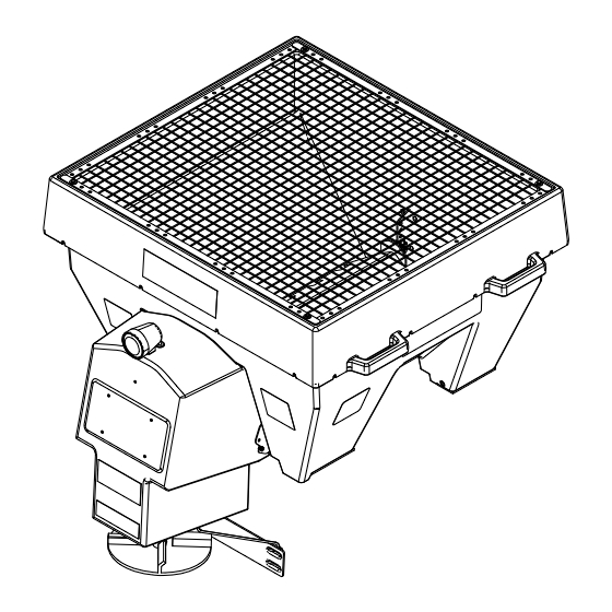
Product Overview g031529 Figure 13 1. Material deflector 3. Hopper cover 2. Spinner assembly Controls Material Deflector The material deflector controls the spread of materials; you can adjust the controls to provide different spread patterns; refer to Adjusting the Material Deflectors (page 12). -
Page 11: Specifications
Operation a jam. When flashing red, it indicates that the spreader is jammed or has been disconnected. The speed display for the jammed motor flashes Note: Determine the left and right sides of the to indicate where the jam is. machine from the normal operating position. -
Page 12: Operating The Spreader
Operating the Spreader Adjusting the Material Deflectors DANGER You can adjust the material deflectors by inserting the Hands, feet, and clothing can get caught in deflector pins into the staggered holes around the the moving parts of the spreader and cause spinner (Figure 15). -
Page 13: Adjusting The Baffle
Adjusting the Baffle Empty the spreader hopper; refer to Unloading the Spreader (page 13). Unplug the spinner harness from the main wire harness. Remove the top screen from the spreader. Remove the hardware securing the baffle to the inside of the spreader (Figure 17). -
Page 14: Operating Tips
Operating Tips • Know the area in which you are working; hidden obstructions such as curbs, sidewalks, and pipes, can damage the spreader or vehicle. • Do not let the ice build up; always start as soon as possible. • Always wear your seatbelt when spreading. -
Page 15: Maintenance
Maintenance WARNING Failure to properly maintain the machine could result in premature failure of machine systems causing possible harm to you or bystanders. Keep the machine well maintained and in good working order as indicated in these instructions. Note: Determine the left and right sides of the machine from the normal operating position. Recommended Maintenance Schedule(s) Maintenance Service Maintenance Procedure... -
Page 16: Troubleshooting
Troubleshooting Problem Possible Cause Corrective Action The controller has no power. 1. The spade connector is not connected 1. Connect the spade connector to the to the ignition switch power source. ignition switch power source. 2. The the ignition switch, battery, or 2.
Need help?
Do you have a question about the VBX 3000 and is the answer not in the manual?
Questions and answers