Table of Contents
Advertisement
Quick Links
www.ti.com
User's Guide
BQ77216 Evaluation Module
Willy Massoth
The BQ77216EVM evaluation module (EVM) is a complete evaluation system for the BQ77216, a 3-cell to 16-
cell Li-Ion battery protection integrated circuit. The EVM consists of a BQ77216 circuit module which is used for
simple evaluation of the BQ77216 protection function. The circuit module includes one BQ77216 integrated
circuit (IC), thermistor, and all other onboard components necessary to signal the condition from overcharge,
overdischarge, and overtemperature in a 16-series cell Li-Ion or Li-Polymer battery pack. The circuit module
connects directly across the cells in a battery, or can be connected with a power supply and the included cell
simulator resistors.
space
1
Features...................................................................................................................................................................................3
Contents........................................................................................................................................................................3
1.2 Ordering Information..........................................................................................................................................................
1.4 Required Equipment..........................................................................................................................................................
2.1 Before You Begin...............................................................................................................................................................
2.2 Warnings and Cautions......................................................................................................................................................
Start..........................................................................................................................................................................4
Simulator.....................................................................................................................................................................6
3.2 Reducing the Cell Count....................................................................................................................................................
3.3 Connecting Cells................................................................................................................................................................
3.4 Hardware Configuration.....................................................................................................................................................
Layout......................................................................................................................................................................8
Materials.................................................................................................................................................................12
4.3
Schematics.......................................................................................................................................................................13
6 Revision History...................................................................................................................................................................
Figure 4-1. Top Silk Screen.........................................................................................................................................................
Figure 4-2. Top Assembly............................................................................................................................................................
Layer...................................................................................................................................................................9
Figure 4-4. Bottom Layer...........................................................................................................................................................
Screen..................................................................................................................................................10
Assembly.....................................................................................................................................................11
Figure 4-7. Schematic Diagram.................................................................................................................................................
Figure 4-8. Cell Simulator..........................................................................................................................................................
Table 1-1. Ordering Information...................................................................................................................................................
Table 3-1. Reducing Cell Count...................................................................................................................................................
SLUUC95A - AUGUST 2020 - REVISED NOVEMBER 2020
Submit Document Feedback
ABSTRACT
Table of Contents
Guide....................................................................................................................................4
Use.................................................................................................................................................6
Construction..........................................................................................................8
Instruments.....................................................................................................................16
List of Figures
Operation........................................................................................................................5
List of Tables
Summary..........................................................................................................................3
Copyright © 2020 Texas Instruments Incorporated
Summary.........................................................................................3
Table of Contents
3
3
4
4
6
6
7
16
8
9
10
14
15
3
6
BQ77216 Evaluation Module
1
Advertisement
Table of Contents

Related Manuals for Texas Instruments BQ77216


Summary of Contents for Texas Instruments BQ77216
-
Page 1: Table Of Contents
The BQ77216EVM evaluation module (EVM) is a complete evaluation system for the BQ77216, a 3-cell to 16- cell Li-Ion battery protection integrated circuit. The EVM consists of a BQ77216 circuit module which is used for simple evaluation of the BQ77216 protection function. The circuit module includes one BQ77216 integrated circuit (IC), thermistor, and all other onboard components necessary to signal the condition from overcharge, overdischarge, and overtemperature in a 16-series cell Li-Ion or Li-Polymer battery pack. - Page 2 Trademarks www.ti.com Table 4-1. BQ77216 Circuit Module Bill of Materials......................... Trademarks All trademarks are the property of their respective owners. BQ77216 Evaluation Module SLUUC95A – AUGUST 2020 – REVISED NOVEMBER 2020 Submit Document Feedback Copyright © 2020 Texas Instruments Incorporated...
-
Page 3: Features
Refer to the physical construction section for board details. 1.3 BQ77216 Circuit Module Performance Specification Summary This section summarizes the performance specifications of the BQ77216 circuit module in its default 16-cell series FET configuration. Typical voltage depends on the number of cells configured. The board does not control current. If populating additional components limit currents to appropriate levels. -
Page 4: Bq77216 Evm Getting Started Guide
2.3 Quick Start The BQ77216 is configured for cell count by the connections on the board. By default the board is set up for 16 cells and this quick start is for all 16 cells. When fewer cells are used, refer to... -
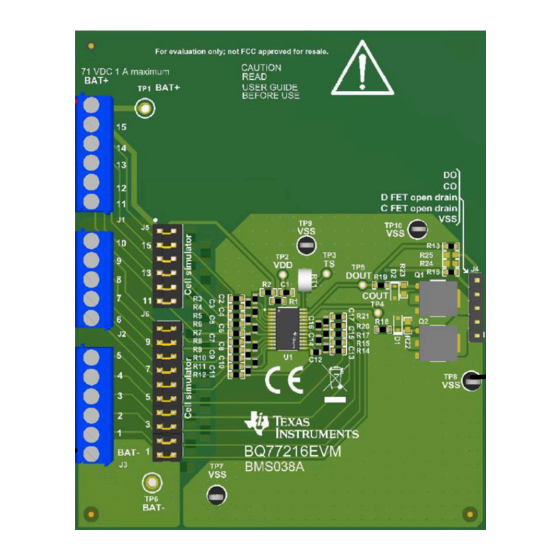
Page 5: Figure 2-1. Evm Connection For Basic Operation
BQ77216 EVM Getting Started Guide 2. Connect a 0-V DC power supply capable of 250 mA minimum between the “BAT-” and "BAT+" terminals and adjust to approximately 45 V. 3. Connect a meter to a VSS test point and monitor the COUT or DOUT test points, or the corresponding signals at J4 terminals 4 or 5. -
Page 6: Bq77216 Circuit Module Use
3.2 Reducing the Cell Count The BQ77216 cell count is reduced by shorting unused cells, normally from the top down but cells between the top and bottom may be shorted. The inputs are usually shorted at the IC as shown in the data sheet. The bottom cell must be used for proper operation. -
Page 7: Hardware Configuration
If using these patterns for evaluation monitor the temperature of the board and limit current as needed. See the schematic in Figure 4-7. SLUUC95A – AUGUST 2020 – REVISED NOVEMBER 2020 BQ77216 Evaluation Module Submit Document Feedback Copyright © 2020 Texas Instruments Incorporated... -
Page 8: Bq77216Evm Circuit Module Physical Construction
See additional information in the configuration and operation sections of this document. Figure 4-1 Figure 4-6 show the board layout. Figure 4-1. Top Silk Screen BQ77216 Evaluation Module SLUUC95A – AUGUST 2020 – REVISED NOVEMBER 2020 Submit Document Feedback Copyright © 2020 Texas Instruments Incorporated... -
Page 9: Figure 4-2. Top Assembly
BQ77216EVM Circuit Module Physical Construction Figure 4-2. Top Assembly Figure 4-3. Top Layer SLUUC95A – AUGUST 2020 – REVISED NOVEMBER 2020 BQ77216 Evaluation Module Submit Document Feedback Copyright © 2020 Texas Instruments Incorporated... -
Page 10: Figure 4-4. Bottom Layer
BQ77216EVM Circuit Module Physical Construction www.ti.com Figure 4-4. Bottom Layer Figure 4-5. Bottom Silk Screen BQ77216 Evaluation Module SLUUC95A – AUGUST 2020 – REVISED NOVEMBER 2020 Submit Document Feedback Copyright © 2020 Texas Instruments Incorporated... -
Page 11: Figure 4-6. Bottom Assembly
BQ77216EVM Circuit Module Physical Construction Figure 4-6. Bottom Assembly SLUUC95A – AUGUST 2020 – REVISED NOVEMBER 2020 BQ77216 Evaluation Module Submit Document Feedback Copyright © 2020 Texas Instruments Incorporated... -
Page 12: Bill Of Materials
4.2 Bill of Materials The bill of materials for the circuit module is shown in Table 4-1. Substitute parts may be used in the manufacturing of the assembly. Table 4-1. BQ77216 Circuit Module Bill of Materials Designator Quantity Value PartNumber... -
Page 13: Schematics
BQ77216EVM Circuit Module Physical Construction Table 4-1. BQ77216 Circuit Module Bill of Materials (continued) Designator Quantity Value PartNumber Manufacturer Description PackageReference SH-J1, SH-J2, SH-J3, SH-J4, SH-J5, SH-J6, SH-J7, SH-J8, SH-J9, Shunt, 100mil, Gold SNT-100-BK-G Samtec Shunt SH-J10, SH-J11, SH-J12,... -
Page 14: Figure 4-7. Schematic Diagram
CFETD CFETD 1.0k 0.1uF 1.0k 0.1uF 1.0k 0.1uF BAT- 1.0M 1.0M 1.0M 1.0M TP10 Net-Tie BQ7721602PWR Figure 4-7. Schematic Diagram BQ77216 Evaluation Module SLUUC95A – AUGUST 2020 – REVISED NOVEMBER 2020 Submit Document Feedback Copyright © 2020 Texas Instruments Incorporated... -
Page 15: Figure 4-8. Cell Simulator
BQ77216EVM Circuit Module Physical Construction Cell Simulator - Populate shunts to use cell simulator if not connecting a battery. BAT- Figure 4-8. Cell Simulator SLUUC95A – AUGUST 2020 – REVISED NOVEMBER 2020 BQ77216 Evaluation Module Submit Document Feedback Copyright © 2020 Texas Instruments Incorporated... -
Page 16: Related Documents From Texas Instruments
5 Related Documents from Texas Instruments • Texas Instruments, BQ77216 Voltage and Temperature Protection for 2 to 16-Series Cell Li-Ion Batt w/ Int Delay Timer data sheet 6 Revision History NOTE: Page numbers for previous revisions may differ from page numbers in the current version. - Page 17 STANDARD TERMS FOR EVALUATION MODULES Delivery: TI delivers TI evaluation boards, kits, or modules, including any accompanying demonstration software, components, and/or documentation which may be provided together or separately (collectively, an “EVM” or “EVMs”) to the User (“User”) in accordance with the terms set forth herein.
- Page 18 www.ti.com Regulatory Notices: 3.1 United States 3.1.1 Notice applicable to EVMs not FCC-Approved: FCC NOTICE: This kit is designed to allow product developers to evaluate electronic components, circuitry, or software associated with the kit to determine whether to incorporate such items in a finished product and software developers to write software applications for use with the end product.
- Page 19 www.ti.com Concernant les EVMs avec antennes détachables Conformément à la réglementation d'Industrie Canada, le présent émetteur radio peut fonctionner avec une antenne d'un type et d'un gain maximal (ou inférieur) approuvé pour l'émetteur par Industrie Canada. Dans le but de réduire les risques de brouillage radioélectrique à...
- Page 20 www.ti.com EVM Use Restrictions and Warnings: 4.1 EVMS ARE NOT FOR USE IN FUNCTIONAL SAFETY AND/OR SAFETY CRITICAL EVALUATIONS, INCLUDING BUT NOT LIMITED TO EVALUATIONS OF LIFE SUPPORT APPLICATIONS. 4.2 User must read and apply the user guide and other available documentation provided by TI regarding the EVM prior to handling or using the EVM, including without limitation any warning or restriction notices.
- Page 21 Notwithstanding the foregoing, any judgment may be enforced in any United States or foreign court, and TI may seek injunctive relief in any United States or foreign court. Mailing Address: Texas Instruments, Post Office Box 655303, Dallas, Texas 75265 Copyright © 2019, Texas Instruments Incorporated...
- Page 22 TI products. TI’s provision of these resources does not expand or otherwise alter TI’s applicable warranties or warranty disclaimers for TI products. Mailing Address: Texas Instruments, Post Office Box 655303, Dallas, Texas 75265 Copyright © 2020, Texas Instruments Incorporated...
- Page 23 Mouser Electronics Authorized Distributor Click to View Pricing, Inventory, Delivery & Lifecycle Information: Texas Instruments BQ77216EVM...
Need help?
Do you have a question about the BQ77216 and is the answer not in the manual?
Questions and answers