Table of Contents
Advertisement
SEDECAL
Technical Publication
SM-0524R4
Service Manual
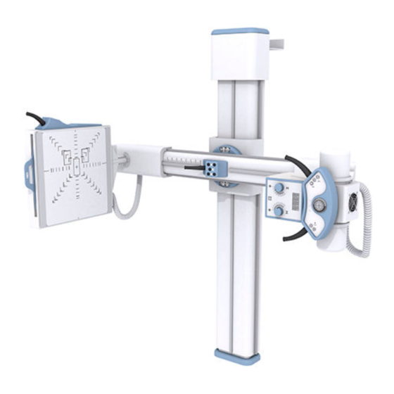
SEDECAL X
Universal Radiographic System
Este producto ostenta una marca CE de acuerdo con las disposiciones de la Directiva 93/42/CEE del 14 de Junio de 1993 sobre Productos Médicos.
This product bears a CE marking in accordance with the provisions of the 93/42/EEC MDD dated June 14, 1993.
Advertisement
Table of Contents

Subscribe to Our Youtube Channel
Related Manuals for Sedecal X


Summary of Contents for Sedecal X
- Page 1 Technical Publication SM-0524R4 Service Manual SEDECAL X Universal Radiographic System Este producto ostenta una marca CE de acuerdo con las disposiciones de la Directiva 93/42/CEE del 14 de Junio de 1993 sobre Productos Médicos. This product bears a CE marking in accordance with the provisions of the 93/42/EEC MDD dated June 14, 1993.
- Page 3 Universal Radiographic System Service Manual REVISION HISTORY REVISION DATE REASON FOR CHANGE AUG 2, 2004 First edition OCT 4, 2005 Schematics JUN 28, 2006 New Balance Adjustment System FEB 08, 2011 Schematics MAY 17, 2011 Renewal Parts This Document is the English original version, edited and supplied by the manufacturer. The Revision state of this Document is indicated in the code number shown at the bottom of this page.
- Page 4 Universal Radiographic System Service Manual SAFETY SYMBOLS The following safety symbols will be used in the equipment. Their meaning are described below. Attention, consult accompanying documents. Ionizing radiation. Type B equipment. Dangerous voltage. Ground. This symbol indicates that the waste of electrical and electronic equipment must not be disposed as unsorted municipal waste and must be collected separately.
-
Page 5: Table Of Contents
Alignment of Light Field with X-ray Field ......4.4.2 Perpendicularity Adjustment of X-ray Beam with Image Receptor . . . 4.4.3 Centering of X-ray Field and Image Receptor . -
Page 6: Section Page
Universal Radiographic System Service Manual Section Page RENEWAL PARTS ............Manual Version . -
Page 7: Introduction
• PRE-INSTALLATION CHECKS Prior to beginning installation it is recommended to inspect the site and verify that the X-ray room complies with requirements such as: Space Requirements to allow installation and system movements must • consider the maximum dimensions and travels of the equipment. - Page 8 Universal Radiographic System Service Manual Illustration 1-1 Dimensions 1400 1095 1165 Reception Area Reference Axis 1000 2000 2260 SM-0524R4...
-
Page 9: Unpacking
UNPACKING The whole system is shipped in several boxes to facilitate transport and installation. Upon receipt of the X-ray unit and associated equipment, inspect all shipping containers for signs of damage. If damage is found, notify the carrier or his agent immediately. - Page 10 Universal Radiographic System Service Manual This page intentionally left blank. SM-0524R4...
-
Page 11: Installation
(optional model) has the Receptor placed at the right side of the unit, position of the Control Unit (Wall Box), Bucky, Tube-Collimator Assembly, ceiling pole and clamp to fasten the HV Cables of the X-ray Tube should be installed in the reverse side. Perform Installation following the order described below. - Page 12 Universal Radiographic System Service Manual Move the Column and prepare the anchorages. Distances shown on Illustration 3-2 may also be taken as Note reference to mark the anchoring holes position. Illustration 3-2 Drill Template 4 wall anchoring holes for screws diam. 8 (Upper Support of the Column) 2 wall anchoring holes for screws diam.
- Page 13 Universal Radiographic System Service Manual Position the Column and make it firm to floor and wall. Check that it is properly levelled on both lateral sides and on the front. Make sure the Column is firmly anchored. (Refer to Illustration 3-3.) It is recommended that the upper part of the Column should be Note placed slightly leaned towards the wall with its top in a closer...
- Page 14 Universal Radiographic System Service Manual Install the X-ray Tube in the Upper Support of the Column using the Collimator Adaptation Ring and its four Safety Screws (Allen). Before installing the Collimator, unscrew equally the four Centering Adjustment and Safety Screws (Allen) to allow the Collimator installation in the Collimator Adaptation Ring.
- Page 15 Universal Radiographic System Service Manual Remove the Bucky Lock-Lever. Install the Bucky Assembly inserting it into the lower axis of the Swivel Arm. Re-install the Bucky Lock-Lever keeping the indicator plate between both nylon washers, and the metallic washers close to the lever. Illustration 3-5 Bucky Lock-Lever INDICATOR PLATE...
- Page 16 Universal Radiographic System Service Manual Install the Control Unit on the wall near the Column (refer to Illustration 3-2). For the Manual version: Install the lower cover of the Control Unit Box. Identify and separate the cables to be connected to the Control Unit and the cables to be connected to the Generator Cabinet.
- Page 17 Universal Radiographic System Service Manual Cables to be connected directly in the Generator Cabinet must be routed through the lower cables entrance of the Control Unit. Verify that the transformer and the fuses of the Control Unit Box are in accordance to the power line. (Refer to Maps I/M-041 and A6408-xx).
- Page 18 Universal Radiographic System Service Manual Connect to the Control Unit Board (A3194- -XX) all connectors and wires from the main harness (J1, J2, wires to TS1 and TS2) (refer to Interconnections Map A6541-03-S). Connect to the Generator the cables from the main harness (Stator, Bucky and ground (GND) cables routed directly from the Column) (for these connections refer to Interconnections Map A6541-03-S and also to Generator Service Manual).
- Page 19 Make sure that they are all straight and that the splits in the pins are open (parallel to sides). Prepare the High Voltage terminals that will be installed in the X-ray Tube receptacles. Apply Silicone Paste over the entire surface of the Plug including the Pins.
- Page 20 Universal Radiographic System Service Manual Illustration 3-9 Covers and HV Cables Clamp TOP COVER HV CABLES CLAMP SAFETY LOCKING ROD SAFETY LOCKING ROD BASE COVER Plug the Control Unit and turn the system on. Check that all controls and movements operate correctly. SM-0524R4...
-
Page 21: Adjustments
Note suggested tools or equivalent. BALANCE TEST OF THE SWIVEL ARM AND CENTRAL CARRIAGE This section only applies to systems where the X-ray Tube or the Note Collimator has to be replaced by a new different X-ray Tube or Collimator (different weight). -
Page 22: Swivel Arm Balance In Horizontal Position
Universal Radiographic System Service Manual 4.2.1 SWIVEL ARM BALANCE IN HORIZONTAL POSITION Turn the unit ON. Place the Swivel Arm in horizontal position and open SID at maximum meters. Press the “Rotation” button and check that the Swivel Arm is balanced, that is, the Swivel Arm should not tilt in any direction without force applied at any point. -
Page 23: Central Carriage Balance For Manual Version
Universal Radiographic System Service Manual 4.2.2 CENTRAL CARRIAGE BALANCE FOR MANUAL VERSION With the unit turned ON. Place the Swivel Arm in horizontal position and open SID at 1.5 meters. Re-install the Safety Locking Rod in the Central Carriage. Remove the Top Cover of the Column. Disengage the Spring located on the Top of the Column (only one end). - Page 24 Universal Radiographic System Service Manual Carefully, remove the Safety Locking Rod from the Central Carriage. Check that the Central Carriage is correctly balanced. It must remain in position when it is released and needs the same strength (approx. a force of 8 kg) for moving it up or down.
-
Page 25: Central Carriage Balance For Motorized Version
Universal Radiographic System Service Manual 4.2.3 CENTRAL CARRIAGE BALANCE FOR MOTORIZED VERSION With the unit turned ON. Place the Swivel Arm in horizontal position and open SID at 1.5 meters. Re-install the Safety Locking Rod in the Central Carriage. Remove the Top Cover of the Column. Loosen slightly the three Safety Screws of the Motor. - Page 26 Universal Radiographic System Service Manual Carefully, remove the Safety Locking Rod from the Central Carriage. Check that the Central Carriage is correctly balanced. It must remain in position when it is released and needs the same strength (approx. a force of 8 kg) for moving it up or down.
-
Page 27: Adjustament Of Motorized Movements Of The Swivel Arm
Universal Radiographic System Service Manual ADJUSTMENT OF MOTORIZED MOVEMENTS OF THE SWIVEL ARM Perfom this section only during Periodic Maintenance tasks, it is Note factory adjusted and is not necessary during the unit installation. The motorized movements of the Swivel Arm (SID and Vertical movements) are blocked automatically for safety reasons when an obstacle is found in its travel applying a strength above 15 ¦... -
Page 28: Adjusment Of Sid Movement Of The Receptor Assembly
Universal Radiographic System Service Manual 4.3.2 ADJUSTMENT OF SID MOVEMENT OF THE RECEPTOR ASSEMBLY With the unit turned ON. Place the Swivel Arm centered in horizontal position and open SID at 1.5 meters. DYNAMOMETER (Pos. 2) DYNAMOMETER (Pos. 1) Press the respective button to reduce the SID and check with a Dynamometer located in contact with the inner side of the Receptor (Table--Top) that the horizontal movement closing the SID is blocked when a strength of 15 ¦... -
Page 29: Alignment Of X-Ray Beam
Universal Radiographic System Service Manual ALIGNMENT OF X-RAY BEAM Place the Swivel Arm in vertical position. The Tube-Collimator Assembly has to be perfectly aligned with the Bucky Assembly. Check with a level correct horizontal position of both assemblies. Place SID at 1 meter. - Page 30 Universal Radiographic System Service Manual Turn on Collimator light and center the Collimator in relation to the Bucky Table-Top. Horizontal and transversal position of the light axes projected by the Collimator Lamp must be in line with the axes or film sizes marked on the Table-Top.
- Page 31 Check that the X-ray Field falls just within the image of the inner rectangle of the Collimator Test Tool. If an edge of the X-ray Field falls out of the inner rectangle means a misalignment of the Light Field respect to the X-ray Field. The maximum misalignment allowed is 2 % of SID (for SID 1m = 2 cm tolerance).
- Page 32 Beam Alignment Test Tool with the Collimator Test Tool. Based on next illustration, the criteria for SID at 1 meter is: -- If the image of the two balls overlap (A) the X-ray Beam is perpendicular to within 0.5 -- If the image of the top ball (larger shadow) intercepts the first circle (B), the X-ray Beam is about 1.5...
-
Page 33: Alignment Of Light Field With X-Ray Field
Universal Radiographic System Service Manual 4.4.1 ALIGNMENT OF LIGHT FIELD WITH X-RAY FIELD Place the Swivel Arm in vertical position. The Tube-Collimator Assembly has to be perfectly aligned with the Bucky Assembly. Check with a level correct horizontal position of both assemblies. - Page 34 Universal Radiographic System Service Manual Check on the processed film the adjustment required to meet the Light Field with the X-ray Field. Identify the deviation on the axes imaged on the film. PROCESSED FILM COLLIMATED LIGHT FIELD COLLIMATED X-RAY FIELD...
- Page 35 Universal Radiographic System Service Manual Do not remove the Collimator Test Tool from its original position and adjust the Light Field by moving the Collimator Unit and/or the Collimator Lamp. Collimator Lamp must be ON during Light Field adjustment. Modify Collimator position by carefully unscrewing and screwing the four Centering Adjustment and Safety Screws (Allen) until the Light Field coincides with the axes reference imaged (numbers and dots) on the processed film.
-
Page 36: Perpendicularity Adjustment Of X-Ray Beam With Image Receptor
Universal Radiographic System Service Manual 4.4.2 PERPENDICULARITY ADJUSTMENT OF X-RAY BEAM WITH IMAGE RECEPTOR In case that perpendicularity is out of tolerance (top ball is out of first circle), adjust perpendicularity as follows: Place the Swivel Arm in vertical position. The Tube-Collimator Assembly has to be perfectly aligned with the Bucky Assembly. - Page 37 Universal Radiographic System Service Manual Illustration 4-10 Levelling Rods of the Tube-Collimator Assembly Support SAFETY SCREWS PIVOTATION LOCKING RATCHET LOCK TOOTH SETSCREWS LEVELING SCREWS (ALLEN M6) SAFETY SCREWS (ALLEN M8) SAFETY SCREWS PIVOTATION LOCKING RATCHET OF THE LOCK TOOTH TUBE-COLLIMATOR ASSEMBLY LEVELLING SCREWS LOCK-LEVER FOR ROTATION OF TUBE-COLLIMATOR ASSEMBLY...
-
Page 38: Centering Of X-Ray Field And Image Receptor
4.4.3 CENTERING OF X-RAY FIELD AND IMAGE RECEPTOR The error between centers of the X-ray Field and the Image Receptor should not be greater than 2% of the SID. (for SID 1m = 2 cm tolerance). CENTER OF THE IMAGE... -
Page 39: Sid Indicator Test
SID INDICATOR TEST Before starting with the SID Indicator Test, the Alignment of X-Ray Note Beam Test and the Alignment of Light Field with X-Ray Field Test should be performed. Place the Swivel Arm in vertical position. The Tube-Collimator Assembly has to be perfectly aligned with the Bucky Assembly. - Page 40 Place a small signal on the circle in order to mark the position. Illustration 4-12 Light Field over SID Test Stand Tool Load on the cassette film Tray with a cassette film of 24 x 30 cm centered and insert it. Make an exposure at 60 kVp, 1 mAs.
- Page 41 Film (refer to Illustration 4-14). Illustration 4-14 Radius in Processed Film SIGNAL PROCESSED FILM With the measurements obtained on the step-9., calculate the “X” value, where: (d/2) x h (D/2) - - (d/2) The SID value to calculate will be:...
-
Page 42: Field Size Indicator Test
Position SID at 1 meter (use the SID scale on the Column). Open the Collimator blades to set a Field Size of 24 x 30 cm for SID 1 m. Turn on the Collimator Light and center the Collimator in relation to the Bucky Table-Top. - Page 43 Universal Radiographic System Service Manual Load on the Cassette Film Tray with a Cassette Film of 35 x 43 cm centered and insert it. Make an exposure at 60 kVp, 1 mAs. Process film and check the following measurements known (refer to...
-
Page 44: Collimator Lamp Brightness Test
Position SID at 1 meter (use the SID scale of the Column). Open the Collimator shutter by means of Collimator Control Knobs and set a Field Size of 25 x 25 cm for SID 1m. Turn on the Collimator Light and center the Collimator in relation to the Bucky Table-Top. - Page 45 Universal Radiographic System Service Manual Place the Light Meter on the Table-Top with sensor directed toward the Light Source. Place the Light Meter in the center of one quadrant of the light field (refer to Illustration 4-18). Illustration 4-18 Light Meter on Table-Top LIGHT SENSOR ON THE 2nd QUADRANT 1st QUADRANT 4th QUADRANT...
-
Page 46: Collimator Light Field Contrast Ratio
Position SID at 1 meter (use the SID scale of the Column). Open the Collimator blades to set a Field Size of 25 x 25 cm for SID 1m. Turn ON the Collimator Light and center the Collimator in relation to the Bucky Table-Top. - Page 47 Universal Radiographic System Service Manual Turn ON the Collimator Light. Measure the maximum illumination; this should occur near the field center. Slide the light sensor along the Table-Top, and locate the point where the illumination drops to a 75% of the maximum.
- Page 48 Universal Radiographic System Service Manual This page intentionally left blank. SM-0524R4...
-
Page 49: Maintenance
Universal Radiographic System Service Manual SECTION 5 MAINTENANCE The purpose of this Periodic Maintenance is to guarantee a continue safe performance of the Unit, to increase serviceability, to reduce costs (down time, repairs, etc.) and to assure the safety (personal risk). The following checks and maintenance procedures, at the the suggested intervals, are the manufacturer’s recommendation for the most effective Periodic Maintenance schedule for this Unit. -
Page 50: Electrical Checks
Universal Radiographic System Service Manual ELECTRICAL CHECKS ELECTRICAL CHECKS ELECTRICAL CABLES Check that all electrical connections are firm and secure and that all cable clamps and AND CONNECTIONS strain reliefs are in place. Also check that connectors do not have exposed wires and check cable sheaths for wear and fraying. -
Page 51: Renewal Parts
Universal Radiographic System Service Manual SECTION 6 RENEWAL PARTS MANUAL VERSION SM-0524R4... - Page 52 Universal Radiographic System Service Manual ITEM DESCRIPTION REFERENCE REMARKS COLUMN Spring Kit SAT- -A8280- -01 Solenoid Kit SAT- -A9808- -01 Steel Cable Kit SAT- -12040- -01 Concentric Bearing Kit SAT- -51501110 includes 2 bearings Lateral Guide SAT- -S02.01.004 Top Guide Kit SAT- -A9810- -01 SM-0524R4...
- Page 53 Universal Radiographic System Service Manual SM-0524R4...
- Page 54 Universal Radiographic System Service Manual ITEM DESCRIPTION REFERENCE REMARKS CENTRAL CARRIAGE + ARM Lower Side Bearing Kit SAT- -A9811- -01 Concentric Bearing Kit SAT- -51501110 each kit includes 2 bearings Eccentric Bearing Kit SAT- -A9812- -01 each kit includes 2 bearings Spring Kit SAT- -S02.03.006 includes 4 springs...
- Page 55 Universal Radiographic System Service Manual SM-0524R4...
- Page 56 Universal Radiographic System Service Manual SM-0524R4...
- Page 57 Universal Radiographic System Service Manual SM-0524R4...
- Page 58 Universal Radiographic System Service Manual ITEM DESCRIPTION REFERENCE REMARKS POWER BOX Transformer SAT- -50509008 Optima Universal Board SAT- -A3127- -01 Line Filter SAT- -50208001 Switch Green SAT- -50613012 Emergency OFF Switch Kit SAT- -A9830- -01 Fuses Kit SAT- -A9817- -01 SM-0524R4...
- Page 59 Universal Radiographic System Service Manual ITEM DESCRIPTION REFERENCE REMARKS CABLES Stator Cable SAT- -A3052- -02 Stator Cable SAT- -A7014- -02 Power Cable SAT- -A3153- -02 Vertical Cable SAT- -A3154- -02 SID Cable SAT- -A3155- -02 Cable Rotation SAT- -A3158- -02 Control Cable SAT- -A3157- -02 Collimator Panel Cable...
- Page 60 Universal Radiographic System Service Manual This page intentionally left blank. SM-0524R4...
-
Page 61: Motorized Version
Universal Radiographic System Service Manual MOTORIZED VERSION SM-0524R4... - Page 62 Universal Radiographic System Service Manual ITEM DESCRIPTION REFERENCE REMARKS COLUMN SAT- -A8280- -01 - - Bucky - - Canon 50G Spring Kit SAT- -A8281- -01 - - Radax - - Trixell Gear 21 Z SAT- -12002- -01 Vertical Motor Kit SAT- -A9819- -01 Vertical Motor Chain Kit SAT- -A9820- -01...
- Page 63 Universal Radiographic System Service Manual SM-0524R4...
- Page 64 Universal Radiographic System Service Manual ITEM DESCRIPTION REFERENCE REMARKS CENTRAL CARRIAGE + ARM Lower Side Bearing Kit SAT- -A9811- -01 Concentric Bearing SAT- -51501110 each kit includes 2 bearings Eccentric Bearing Kit SAT- -A9812- -01 each kit includes 2 bearings Spring Kit SAT- -S02.03.006 includes 4 springs...
- Page 65 Universal Radiographic System Service Manual ITEM DESCRIPTION REFERENCE REMARKS Bucky SAT- -6685- -11 Ion Chamber SAT- -6695- -21 Grid SAT- -6697- -03 Tube Fan SAT- -53103020 Option Collimator SAT- -6693- -XX Depends on Collimator installed Tube SAT- -6690- -XX Depends on Tube installed SM-0524R4...
- Page 66 Universal Radiographic System Service Manual SM-0524R4...
- Page 67 Universal Radiographic System Service Manual SM-0524R4...
- Page 68 Universal Radiographic System Service Manual SM-0524R4...
- Page 69 Universal Radiographic System Service Manual ITEM DESCRIPTION REFERENCE REMARKS POWER BOX Transformer SAT- -50509033 Optima Universal Board SAT- -A3194- -03 Line Filter SAT- -50208001 Switch Green SAT- -50613012 Emergency OFF Switch Kit SAT- -A9830- -01 Fuses Kit SAT- -A9831- -01 SM-0524R4...
- Page 70 Universal Radiographic System Service Manual ITEM DESCRIPTION REFERENCE REMARKS CABLES Stator Cable SAT- -A3052- -02 Stator Cable SAT- -A7014- -02 Power Cable SAT- -A3153- -02 Motor Cable SAT- -A3386- -01 Motor Harness SAT- -A3386- -02 Display Harness SAT- -A3387- -01 Collimator Harness SAT- -A3388- -01 Rotation Motor Harness...
-
Page 71: Interconnection Maps
Motorized URS A3195- -01 Motorized URS Display IF-001 Bucky Interface (connected as Bucky-1) IF-002 Bucky Interface (connected as Bucky-2) IF-045 US X-ray Bucky Interface IM- -363 AEC Interconnection for URS (optional) IM- -366 Fans Adaptation for Motorized URS (optional) SM-0524R4... - Page 72 Universal Radiographic System Service Manual This page intentionally left blank. SM-0524R4...
- Page 73 SID Locks Cable (A3155-02) ROTATION SID LOCK Rotation Lock Rot. Locks Cable (A3156-02) ROTATION LOCK NAME DATE SHEET / OF IM - 041 DRAWING F.GARCIA 01/07/01 A.DIAZ 01/07/01 REVISED OPTIMA UNIVERSAL SEDECAL Version 02 INTERCONNECTION F. Garcia 01/07/01 DESCRIPTION ISSUED BY DATE...
- Page 75 24 VAC 440 V 0 VAC 415 V T 10A 20 V 400 V +24 V FB1002L Connect according 4 x 2200uF with the input line 240 V STUD +24 VDC 160, 2w 230 V 208 V 1N4007 100 uF...
- Page 77 GENERATOR CABINET HEIGHT Motor Cable (A3386-01) Stator Cable CONTROL Anode Cable Optima URS Motorized Display Cable (A3387-01) PANEL X-RAY Cathode Cable TUBE HV TANK Fan Cable (A7306-XX) (optional) COLLIMATOR Collimator Cable (A3388-01) CARRIAGE SID Cable (A3391-01) Lock-up Cable (A3392-01) ROTATION...
- Page 79 Fan Cable HEIGHT UP (A7306-XX) 230 VAC HEIGHT DOWN 0 VAC Chassis GND Generator NAME DATE SHEET / OF TUBE A6541-03-S Cabinet DRAWING F.GARCIA 06/06/03 A.DIAZ 06/06/03 REVISED SEDECAL MOTORIZED URS CN 07/024 F. García 29/01/08 DESCRIPTION ISSUED BY DATE...
- Page 81 ROTATE NAME DATE SHEET / OF A3194-03 DRAWING F.GARCIA 07/07/03 A.DIAZ 07/07/03 CN 10/512 S.Pérez 27/12/10 REVISED CN 09/339 24/11/09 F. Díaz CN 08/365 F. García 05/12/08 SEDECAL Optima URS Motorized board validated F. García 16/01/04 DESCRIPTION ISSUED BY DATE...
- Page 83 +12V NAME DATE SHEET / OF A3194-03 DRAWING F.GARCIA 07/07/03 A.DIAZ 07/07/03 CN 10/512 S.Pérez 27/12/10 REVISED CN 09/339 24/11/09 F. Díaz CN 08/365 F. García 05/12/08 SEDECAL Optima URS Motorized board validated F. García 16/01/04 DESCRIPTION ISSUED BY DATE...
- Page 85 NAME DATE SHEET / OF J1-3 A3194-03 DRAWING F.GARCIA 07/07/03 A.DIAZ 07/07/03 CN 10/512 S.Pérez 27/12/10 REVISED CN 09/339 24/11/09 F. Díaz CN 08/365 F. García 05/12/08 SEDECAL Optima URS Motorized board validated F. García 16/01/04 DESCRIPTION ISSUED BY DATE...
- Page 87 LAMP COMMON UNDERTABLE LOCK LAMP SID 100 LAMP SID 180 LAMP SID 200 LAMP +12V NAME DATE SHEET / OF A3195-01 F.GARCIA 01/01/01 DRAWING A.DIAZ 02/02/01 REVISED SEDECAL Optima URS Motorized Display CN 01/171 F. GARCIA 10/10/01 DESCRIPTION ISSUED BY DATE...
- Page 89 NAME DATE SHEET / OF I/F- -001 Cable de Inerconexión DRAWING F. GARCIA 15/03/95 REVISED A. DIAZ 15/03/95 TABLE BUCKY INTERFACE Interf. board revised F. GARCIA 14/03/08 SEDECAL Innomed added F. GARCIA 09/09/02 INTERFAZ BUCKY MESA DESCRIPTION ISSUED BY DATE...
- Page 91 NAME DATE SHEET / OF I/F- -002 Cable de Inerconexión DRAWING F. GARCIA 15/03/95 REVISED A. DIAZ 15/03/95 VERTICAL BUCKY INTERFACE Interf board revised F. GARCIA 14/03/08 SEDECAL Innomed added 09/09/02 F. GARCIA INTERFAZ BUCKY VERTICAL DESCRIPTION ISSUED BY DATE...
- Page 93 C2=470 nF, 250 VAC según se muestra. Interconnection Cable NAME DATE SHEET / OF I/F- -045 Cable de Inerconexión DRAWING F. GARCIA 08/08/01 1 / 2 REVISED A. DIAZ 08/08/01 SEDECAL US X- -RAY BUCKY INTERFACE Interf bd. revised 14/03/08 F. García DESCRIPTION ISSUED BY DATE...
- Page 95 C2=470 nF, 250 VAC según se muestra. Interconnection Cable NAME DATE SHEET / OF I/F- -045 Cable de Inerconexión DRAWING F. GARCIA 08/08/01 2 / 2 REVISED A. DIAZ 08/08/01 SEDECAL US X- -RAY BUCKY INTERFACE Interf bd. revised 14/03/08 F. García DESCRIPTION ISSUED BY DATE...
- Page 97 GND Stud (Column) GND Stud Note.-Connect wire 26 to TS1-26 for 220 VAC, or to TS1-27 for 115 VAC NAME DATE SHEET / OF IM - 363 DRAWING F.GARCIA 05/05/05 A.DIAZ 05/05/05 REVISED SEDECAL AEC Interconnection for URS DESCRIPTION ISSUED BY DATE...
- Page 99 10 w +32 VDC FANS CABLE FANS HARNESS TS10 TS11 FAN 3 +24 VDC +24 VDC FAN 4 FAN 5 NAME DATE SHEET / OF IM - 366 DRAWING F.GARCIA 09/09/05 A.DIAZ 09/09/05 REVISED SEDECAL URS/Fans Adaptation DESCRIPTION ISSUED BY DATE...
Need help?
Do you have a question about the X and is the answer not in the manual?
Questions and answers