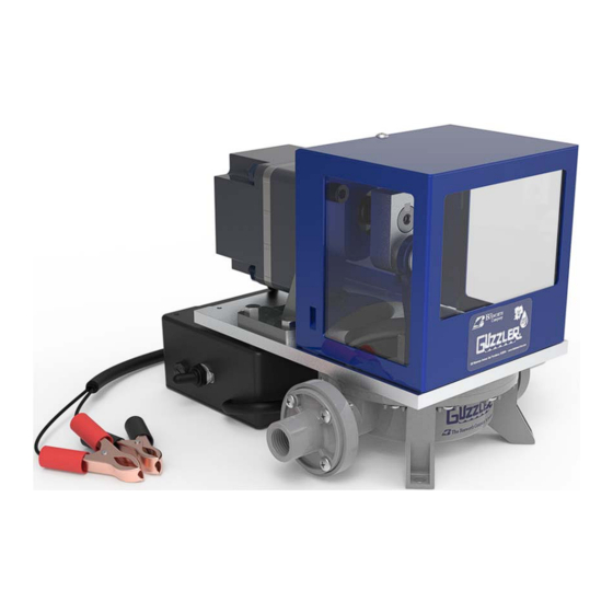
Bosworth Guzzler GE-0404N Operator's Manual
24 vdc single diaphragm pump
Hide thumbs
Also See for Guzzler GE-0404N:
- Operator's manual (10 pages) ,
- Operator's manual (20 pages)

Subscribe to Our Youtube Channel
Related Manuals for Bosworth Guzzler GE-0404N


Summary of Contents for Bosworth Guzzler GE-0404N
- Page 1 D ® GE‐0404N / GE‐0504N ’ M use as Maple Sap Vacuum pumps © Copyright 2023 The Bosworth Company Doc M-PR-09-34-013123 Guzzler® and SapCheck® are registered trademarks of The Bosworth Compa-...
-
Page 2: Table Of Contents
GE-0404N/GE-0504N 24 ……………………………………………………………………………………………………………………………. Power Requirements ………………………………………………………………………………………………………..……. 2 Testing the Pump … …………………………………………………………………………………………………………….…… 2 ………………………………………………………………………………………………………………………………. Protect the Pump from the Elements…………………………………………………………………………………...…… 2 Ventilate Pump to Keep from Overheating……………………………………………………………………………… 3 Quick Connect Couplers between Guzzler and Mainline … ………………………………………………………. 3 Install Shut‐off Valve and Vacuum Gauge at Pump Inlet …………………………………………………………. 3 Minimize Pump Back Pressure ……………………………………………………………………………………………….. 3 Use a Strainer to Keep Foreign Materials and Ice from Entering the Pump …………………………….. 3 Recirculation Line for Best Vacuum ………………………………………………………………………………………… 3 …………………………………………………………………………………………………………… Eliminate Leaks for Best Vacuum ……………………………………………………………………………………………. 4 Isolate the Pump to Find Cause of Vacuum Loss …………………………………………………………………….. ... -
Page 3: Power Requirements
Your Guzzler® GE‐0404N/GE‐0504N 24 vdc diaphragm pump ships fully as‐ sembled. Included with the pump is a spare diaphragm. Additional dia‐ phragms can be purchased through your maple equipment dealer or directly online from The Bosworth Company at www.thebosworthco.com. Your pump’s serial number can be found on the side of the pump gear‐ motor, as shown in Figure 1. Power Requirements The GE‐0404N/GE‐0504N pumps require 24 vdc power. The pump motor is Pump serial number on side of motor a 100 watt motor with rated output current of 6.0 A. When connected to Figure 1 two 60 amp‐hour 12 vdc deep‐discharge batteries wired in series, the pump can operate for 30‐50 hours depending on the amount of sap it transfers in that time and on the level of vacuum it pulls. The above results were obtained based on the pump creating 20 in Hg vacuum. Higher levels of vacuum will shorten the length of time the pump can operate before the batteries need recharging. The pump on/off switch is located on the side of the electrical junction box. (Figure 2) Testing the Pump Before installing the pump in your sugarbush, test your pump by connec ng it to power and turning the Power switch to On. Be sure to connect the On/Off switch and fuse on side of posi ve (red wire) lead from the motor to the posi ve terminal on the electrical junc on box. ... -
Page 4: Ventilate Pump To Keep From Overheating
Vacuum Gauge 1/8” Recircula ng Line valve control and connec on (from sap tank) Shutoff Valve Connec on to Mainline 1/4” vacuum connec‐ Quick Connect Pump on to SapCheck® Coupler Strainer monitoring system Recommended pump setup for use on maple sap collec on lines Figure 4 Ventilate Pump to Keep from Overheating When operating, the pump can develop a motor surface temperature that may exceed 160°F (70°C). If you in‐ stall your pump in an enclosure, ensure that it provides ventilation so that the pump motor has adequate airflow during operation to prevent overheating. Quick Connect Couplers between Guzzler and Mainline We recommend the use of Quick Connect Couplers between the pump inlet and mainline so that the pump can be easily disconnected from and reconnected to your mainline. Install Shut‐off Valve and Vacuum Gauge at Pump Inlet We recommend that you install a shut‐off valve and a vacuum gauge – in that sequence – “in front of” the pump, ... -
Page 5: T B O
Eliminate Leaks for Best Vacuum Your Guzzler Pump can develop 19‐28 in. of Hg vacuum, depending on whether the valves are dry or wet. Because the Guzzler is a low‐cfm (cubic feet of air per minute) pump, even very small leaks can prevent the pump from deliv‐ ering its rated vacuum. Maintain your tap lines to keep your system tight and address problems that can cause vacu‐ um leaks. Isolate the Pump to Find Cause of Vacuum Loss If you experience a loss of vacuum in your system – as registered by the gauge near the pump – slowly turn the shut‐ off valve to isolate the pump from your mainline. DO NOT SHUT THE VALVE SUDDENLY, AS PUMP DAMAGE MAY RESULT. If the gauge begins to return to normal operating vacuum, then the pump is working properly, and the source of the leak is somewhere in your sap lines or taps. If the pump fails to recover normal vacuum, then the pump is the source of the problem. Inspect the pump diaphragms and/or valves for any holes or tears. In the case of the valves, check for and remove any material that may have entered a pump body and lodged in the valve, pre‐ venting the valve from proper opening and closing. Keep Ice from Forming Inside Pump Sap can freeze within the pump body. If the pump is turned on when there is ice in a pump body, it will result in damage to various pump components, including the pump body, valves and diaphragm. If there is a risk of freezing conditions, we recommend that you disconnect the pump from your sap lines when the pump is not running and drain any excess sap from the pump. Some users install a small heat lamp in the enclosure with the pump to prevent ice from forming when the pump is not operating. Drain Sap if Removing Pump from Mainline To shut the pump down and disconnect it from the mainline, first slowly close the shut‐off valve to isolate and main‐... -
Page 6: M - C D
Over time, the elastomer components of the pump (i.e., the diaphragm and valves) will fail. If a diaphragm fails, the pump may continue to develop some vacuum (depending on the size of the hole/tear), but it will be significantly reduced, and you will see sap leaking from the diaphragm in and around the pump guard. When replacing the diaphragm, pay close a en on to the orienta on of various parts. The use of witness marks may be helpful during reassembly. Tools Needed: Philips Head Screwdriver, Flat Head Screwdriver Materials Needed: Blue Loctite 242 Remove pump body from Removing a Diaphragm aluminum moun ng plate Figure 5 1. Disconnect the power. 2. Turn the pump upside down so that it is res ng on the pump guard and motor. With a pencil, mark the side of the moun ng plate next to the pump inlet (the short‐ er of the two ports). 3. Remove the 10 screws holding the pump body to the aluminum moun ng plate (Figure 5). 4. Remove the pump body to expose the diaphragm screw a aching the plas c “bu on” (a plas c support plate) to the diaphragm. 5. Remove the slo ed head screw, washer, bu on, and diaphragm from the base of the plas c clevis (Figure 6). ... -
Page 7: M - C P V
Pump Valve Types There are two valves in each Guzzler pump. One valve is locat‐ ed between the pump body and the inlet port; the other, be‐ tween the pump body and the outlet port. Your Guzzler pump may be equipped with either duckbill valves or umbrella valves, depending on the pump options chosen. GE‐0504x Duckbill valve GE‐0404x Duckbill valve (le : Closed; right: Open) (le : Closed; right: Open) The duckbill valve is shaped like a bird’s beak. When pressure is Figure 8B Figure 8A placed on the outside of the beak, it forces it to close; when pressure is placed on the other end of the valve, it forces the beak to open so that fluid may pass. (Figures 8A‐8B) The duckbill valve on the GE‐0504x series pumps is slightly larger than that on the GE‐0404x pumps. The other kind of valve available for your pump is an umbrella valve. The umbrella valve features a rubber valve with a flat round disk held under ten‐ sion against a plastic plate (the “valve stop”) that contains a number of holes or “pores”. (Figure 9) When pressure is applied to one side of the valve stop, it pushes the rubber Figure 9 disk away from the holes, like an umbrella turning inside out (Figures 10A‐ 10B). When this happens, fluid or air can pass through the holes. When the pressure is reversed, the rubber disk is forced against the holes, making a tight seal to prevent any fluid or air from passing. Either kind of valve can be fouled by material in the sap (e.g., wood shavings from taps, plastic shavings from tubing, etc.) ... - Page 8 Changing the Valves, con nued 4. To replace the umbrella valve, use a pair of pliers to grasp the flat por on of the old umbrella valve and pull the en re valve through the valve stop center retaining hole (Figure 12). Insert the stem of the new valve into the valve stop retaining hole so that the flat por on of the valve is on the same side of the valve stop as the old Use pliers to remove old umbrella valve. Use pliers to grasp the stem of the valve on the other side and pull it com‐ valve from valve stop. pletely through un l it snaps into place. Figure 12 5. Posi on the new umbrella valve (or the inspected and cleaned old valve) between the pump body and the pump inlet flange, taking care to orient the valve as shown in Figure 13. Fasten the pump flange and the valve stop to the pump body using the flange screws. 6. Repeat steps 2‐5, this me with the outlet side of the pump. Be sure to install the outlet valve so it is oriented as shown in Figure 13. 7. Re‐install the pump body. NOTE IF THE VALVES ARE NOT ORIENTED CORRECTLY IN THE Umbrella valve stem points in opposite direc on to PUMP FLANGES, THE PUMP WILL NOT FUNCTION PROPERLY AND fluid flow. COULD BE DAMAGED UPON OPERATION. Figure 13 “I’ve got li le or no vacuum on If you’ve installed a shut‐off valve in front of the vacuum gauge, slowly turn the ...
-
Page 9: T S
The pump motor has built‐in protec on to guard against excessive load con‐ vacuum (27 in Hg) and then di ons, as can occur if the pump is pulling a vacuum in excess of 25 in Hg. stopped. My ba eries are fully Even if the ba eries are fully charged, the motor controller may determine charged. What’s wrong?” that there is insufficient voltage available to support the load on the motor. In some cases, keeping the ba eries charged (as can be done, for example, with a solar recharging system) and opera ng on the range 25.0‐26.0 vdc can provide sufficient power to support loads generated by vacuums on the range 26.0‐28.0 in Hg. If this is not prac cal, then it is recommended to reduce the vacuum that the pump is pulling to a maximum of 25 in Hg so that the pump will con nue to operate un l the ba eries have discharged to the point of providing 18‐20 vdc. For all technical inquiries, please refer to our website, www.thebosworthco.com, Maple Sap Pumps Application, or contact The Bosworth Company. Be sure to have your pump serial number readily available if contacting Technical Support. You can email us at info@thebosworthco.com or call 401‐438‐1110. Technical support is available Mon‐ day‐Friday, 8AM‐4:30 PM. After hours support is provided as resources are available. Doc M-09-34-013123... -
Page 10: P E V
— G GE-0404N Item Part Name 1 Inlet Flange 2 Outlet Flange 3B Bo om Bu on & Stainless Steel Washer 4 Clevis 5 Body 6B Intermediate Ring 7C Motor Moun ng Plate 12 Miscellaneous Hardware (10‐24 Screws & Nuts) 12C TH1/4‐20x1/2 (1) Diaphragm Screw 13 Diaphragm 14 Flapper Valves 15 Umbrella Valves (Umbrella valves (2), Valve Stops (2), O‐ rings (4), Screws & Nuts) 16 Duckbill Valves 18C ... - Page 11 — G GE-0504N Item Part Name 1 Inlet Flange 2 Outlet Flange 3B Bo om Bu on & Stainless Steel Washer 4 Clevis 5 Body 6B Intermediate Ring 7C Motor Moun ng Plate 12 Miscellaneous Hardware (10‐24 Screws & Nuts) 12C TH1/4‐20x1/2 (1) Diaphragm Screw 13 Diaphragm 14 Flapper Valves 15 Umbrella Valves (Umbrella valves (2), Valve Stops (2), O‐ rings (4), Screws & Nuts) 18C Connec ng Rod Bolt & Spacer 19A ...
- Page 12 930 W , RI 02914 888-438-1110 © Copyright 2023 The Bosworth Company...
Need help?
Do you have a question about the Guzzler GE-0404N and is the answer not in the manual?
Questions and answers