Table of Contents
Advertisement
Quick Links
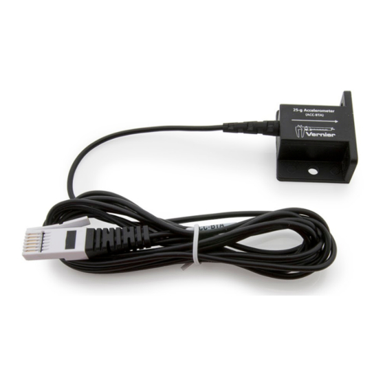
25-g Accelerometer
(Order Code ACC-BTA)
The 25-g Accelerometer can be used for a
wide variety of experiments and
demonstrations, both inside the lab and
outside.
Note: Vernier products are designed for
educational use. Our products are not designed nor are they recommended for
any industrial, medical, or commercial process such as life support, patient
diagnosis, control of a manufacturing process, or industrial testing of any kind.
Compatible Software
See
www.vernier.com/manuals/acc-bta
25-g Accelerometer.
Getting Started
1. Connect the sensor to the interface (LabQuest Mini, LabQuest 2, etc.).
2. Start the appropriate data-collection software (Logger Pro, Logger Lite,
LabQuest App, or Graphical Analysis 4) if not already running, and choose
New from File menu. The software will identify the sensor and load a
default data-collection setup. You are now ready to collect data.
If you are collecting data using a Chromebook™, mobile device such as iPad
or Android™ tablet, or a Vernier wireless interface, please see the following
link for up-to-date connection information:
www.vernier.com/start/acc-bta
Calibrating the Sensor
Optional Calibration Procedure
You do not need to calibrate this sensor. Each sensor is calibrated prior to being
shipped to you. The measurement being made by this sensor is complex and can
be difficult to analyze, so be sure to read the Frequently Asked Questions
section below. In most experiments you can simply use the default calibration,
but then use the software's zeroing option and zero the sensor in the appropriate
orientation.
Most accelerometers, including this one, sense gravity as well as acceleration.
This can make results more difficult to understand, but it provides an easy
calibration method. Calibration may be done using the acceleration due to
gravity. To calibrate the sensor for measuring acceleration in the horizontal
direction, position the accelerometer with the arrow pointing down for the first
calibration point. Define this as –9.8 m/s
the arrow points up and use the reading for the second calibration point. Define
2
this as +9.8 m/s
or +1g. The accelerometer will then read 0 with no
acceleration when held horizontally. If you want to calibrate for measuring
for a list of software compatible with the
2
or –1g. Rotate the accelerometer so
acceleration in the vertical direction, follow the procedure above, but define the
first calibration point as 0g or 0 m/s
Specifications
Power
Range
Accuracy
Frequency response
12-Bit resolution
Stored calibrations for the 25-g
Accelerometer
Care and Maintenance
Do not wrap the cable tightly around the sensor for storage. Repeatedly doing
so can irreparably damage the wires and is not covered under warranty.
How the Sensor Works
The accelerometer senses acceleration using an integrated circuit (IC) originally
designed to control the release of air bags in an automobile. This IC is micro-
machined with very thin "fingers" carved in silicon. These fingers flex when
®
accelerated. They are arranged and connected like the plates of a capacitor. As
the fingers flex, the capacitance changes, and a circuit included in the IC
monitors the capacitance, converting it into a voltage. The op-amp circuit on
our circuit board amplifies and filters this signal.
The accelerometer measures acceleration along the line marked by the arrow on
the sensor. Accelerations are normally measured in either meters per second per
2
second (m/s
) or g. One g is the acceleration due to gravity at the Earth's
2
surface, or 9.8 m/s
2
of –25g (–250 m/s
acceleration, it is easy to produce accelerations larger than this in collisions. In
fact, dropping the accelerometer on a hard surface from even a few centimeters
can produce accelerations of 100g. The accelerometer will not be damaged by
accelerations up to 1000g.
There is inherent noise in the sensing device inside the accelerometer. This
limits the use in low acceleration environments. The noise is typically on the
2
order of 2.5 m/s
peak to peak. Therefore, best results are achieved if the
experiments are designed around magnitudes or changes exceeding 9.8 m/s
The zero will drift with temperature.
1
2
and the second point as 2g or 19.6 m/s
30 mA @ 5 VDC
± 245 m/s
±2.45 m/s
0–100 Hz
0.16 m/s
slope: 127.9 m/s
intercept: –287.9 m/s
. This accelerometer will measure accelerations in the range
2
) to +25g (250 m/s
). Even though this is a fairly large
2
.
2
(±25g)
2
(±0.25g)
2
2
/V
2
2
.
Advertisement
Table of Contents

Subscribe to Our Youtube Channel
Related Manuals for Vernier ACC-BTA


Summary of Contents for Vernier ACC-BTA
- Page 1 If you are collecting data using a Chromebook™, mobile device such as iPad accelerated. They are arranged and connected like the plates of a capacitor. As or Android™ tablet, or a Vernier wireless interface, please see the following the fingers flex, the capacitance changes, and a circuit included in the IC link for up-to-date connection information: monitors the capacitance, converting it into a voltage.
- Page 2 would compress. If you accelerated the scale away from the mass, the spring would stretch. In each case the scale is reading a value corresponding to the normal force on the mass. This reading can be made relative by dividing out the mass, giving units of N/kg, which is the same as m/s The accelerometer measurements can be interpreted in exactly this way.
- Page 3 Rev. 01/31/20 you help prevent potential negative consequences on human health or on the Logger Pro, Logger Lite, Graphical Analysis, Vernier LabQuest, Vernier LabQuest Mini, and other marks environment. The recycling of materials will help to conserve natural resources. shown are our trademarks or registered trademarks in the United States.
Need help?
Do you have a question about the ACC-BTA and is the answer not in the manual?
Questions and answers