Table of Contents
Advertisement
Quick Links
Advertisement
Table of Contents

Related Manuals for Heraeus Electro-Nite CasTemp Wireless


Summary of Contents for Heraeus Electro-Nite CasTemp Wireless
- Page 1 5 June 2020 CasTemp Wireless including CasTemp Superheat page I of VII Instruction and Operating Manual Description CasTemp Wireless including CasTemp Superheat CasTemp Wireless software V6 onwards Document Version: 3.5 Date of Issue: 5 June 2020...
- Page 2 II of VII © 2015 Heraeus Electro-Nite This manual is copyrighted by Heraeus Electro-Nite. No part of this document may be reproduced, transmitted, transcribed, stored in any retrieval system, or translated into any language by any means without the express written permission of Heraeus Electro-Nite.
-
Page 3: Table Of Contents
5 June 2020 CasTemp Wireless including CasTemp Superheat page III of VII Table of contents Safety and Usage Notes ......................... 1 General ............................ 1 Qualified Personnel ........................1 Danger Notices ........................1 Proper Usage ........................... 2 Procedures for Maintenance and Repair .................. 2 Guidelines for Handling Electrostatic Discharge .............. - Page 4 5 June 2020 CasTemp Wireless including CasTemp Superheat page IV of VII 5.2.4 CasTip Parameters ......................32 5.2.5 Checkmate ........................34 5.2.6 Database parameters ...................... 34 5.2.7 LAN 1 & 2 parameters ..................... 35 5.2.8 Remote Viewer (Meltcontrol Set Up) ................36 5.2.9 Level 2 Inputs ........................
- Page 5 5 June 2020 CasTemp Wireless including CasTemp Superheat page V of VII 9.4.3 Telegram Requirements ....................17 9.4.4 Telegram Timings ......................22 9.4.5 Telegram Output ........................ 1 Profibus and Ethernet IP set up ....................1 9.5.1 Profibus Set up ........................1 9.5.2 Ethernet IP Set up ......................
- Page 6 5 June 2020 CasTemp Wireless including CasTemp Superheat page VI of VII Table of Figures Figure 1: CasTemp Wireless QUBE CTW and instrument Overview ............ 7 Figure 2: QUBE CTW module ....................... 7 Figure 3: CasTemp Wireless instrument (CTW) ................... 8 Figure 4: CTW User Guide........................
- Page 7 5 June 2020 CasTemp Wireless including CasTemp Superheat page VII of VII Figure 54: Serial port configuration window ..................45 Figure 55: Serial port configuration settings ..................45 Figure 56: Profibus configuration window ................... 46 Figure 57: EtherNet IP Configuration window ..................46 Figure 58: Physical device window after configuring a number of interfaces ........
-
Page 8: Safety And Usage Notes
We would also point out that the contents of this manual shall not become a part of, or modify, any prior or existing agreement, commitment, or legal relationship. The Purchase Agreement contains the complete and exclusive obligations of Heraeus Electro-Nite. Any statements contained in this manual do not create new warranties or restrict the existing warranty. -
Page 9: Proper Usage
The instrument or instrument components may only be used for the applications described in the manual or the technical description, and only in combination with the equipment, components, and devices of other manufacturers as far as this is recommended or permitted by Heraeus Electro-Nite. -
Page 10: Looking After The Instrument
5 June 2020 CasTemp Wireless including CasTemp Superheat Page 3 material such as conductive foam, anti-static plastic bag, aluminium foil, or paper. Normal plastic bags or foil should not be used under any circumstances. For modules with built-in batteries, ensure that the conductive packing does not touch or short-circuit the battery connections: if necessary cover the connections with insulating tape or material. - Page 11 5 June 2020 CasTemp Wireless including CasTemp Superheat Page 4 • Directive 2014/30/EU concerning electromagnetic compatibility (EMC). • Radio Equipment Directive 2014/53/EU Also: • FCC Title 47 part 15 A copy of the EC Declaration of Conformity certificates can be found in Appendix 1: EC Declaration of Conformity Certificate.
-
Page 12: Wireless Transmitter / Receiver Module
EU Directive 2002/96/EC WEEE, Heraeus Electro-Nite measuring instruments and analysis devices belong to category 9 - monitoring and control instruments. All Heraeus Electro-Nite instruments placed on the market after 1 July 2006 do not contain materials prohibited according to the RoHS directive. -
Page 13: Recycling
If in doubt, ask your national importer or Heraeus Electro-Nite. All old Heraeus Electro-Nite devices can be deposited at Heraeus Electro-Nite premises, free of charge and using a certificated disposal company. The customer pays only for the carriage. -
Page 14: System Overview
5 June 2020 CasTemp Wireless including CasTemp Superheat Page 7 2 System overview 2.1 Introduction The CasTemp Wireless system is an instrument for continuous temperature measurements in continuous casting tundishes and other applications. Continuous steel casting is a process based on the solidification of steel. A well-controlled steel solidification is the precondition for high quality cast products and caster throughput. -
Page 15: Qube Ctw Module
The QUBE CTW module, Figure 2: QUBE CTW module, transceiver unit plugs directly on to the CasTemp sensor and has the following features: • Compatibility with CasTemp and other Heraeus continuous temperature sensors • Robust construction for stable operation in environments -20 C to 60 •... -
Page 16: Castemp Wireless Instrument (Ctw)
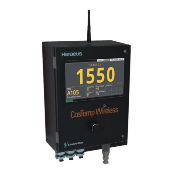
5 June 2020 CasTemp Wireless including CasTemp Superheat Page 9 2.3.2 CasTemp Wireless Instrument (CTW) The CasTemp Wireless instrument, Figure 3: CasTemp Wireless instrument (CTW), controls the QUBE CTW module and displays the liquid steel temperature: • Wall-mounted in an IP67 housing •... -
Page 17: Installing The System
5 June 2020 CasTemp Wireless including CasTemp Superheat Page 10 3 Installing the system In order to achieve a successful installation, all of the necessary components can be obtained in one CTW STARTER PACK ( 5: CTW STARTER PACK). This provides all parts and accessories to Figure allow a customer to begin a wireless continuous temperature measurement. -
Page 18: Qube Ctw Module Charging
5 June 2020 CasTemp Wireless including CasTemp Superheat Page 11 3.1 QUBE CTW Module Charging Charging of the QUBE CTW module can be performed in two ways; using the dedicated power outlet on the CasTemp Wireless instrument or by use of an external QUBE CTW Power Box. 3.1.1 Charging on the instrument In order to charge the QUBE CTW module battery the following steps are required: •... -
Page 19: Figure 9: Ctw Instrument And Qube Ctw Module In Charging Position On Mounting Plate
5 June 2020 CasTemp Wireless including CasTemp Superheat Page 12 3.1.1.1 QUBE CTW module with USB-A inlet • Lift up the Harting cover but DO NOT remove. • Ensure QUBE CTW module charge socket is clean and undamaged. • Plug in the USB plug end of the CTW CHARGING CABLE into the dedicated USB charging port socket on the QUBE CTW module Figure 9 shows the assembled instrument mounting plate, CasTemp Wireless instrument and QUBE CTW... -
Page 20: Charging With The Power Box
5 June 2020 CasTemp Wireless including CasTemp Superheat Page 13 3.1.2 Charging with the Power Box A separate charging option is available for the QUBE CTW module which allows charging to be done without the CasTemp Wireless Instrument. Both QUBE CTW module USB-A and USB-C variants can be charged when using the appropriate CTW CHARGING CABLE with the QUBE CTW Power Box Figure 11: Qube CTW Power Box Figure 12: Input and Output of Power Box... -
Page 21: Critical Safety Information
5 June 2020 CasTemp Wireless including CasTemp Superheat Page 14 The Power Box kit comes with a mounting plate and self-tapping screws to allow for it to be mounted in a suitable place. Figure 14: Power Box mounting plate 3.2 Critical Safety Information The key to a successful installation is to ensure that the system can operate within its operational limits. - Page 22 5 June 2020 CasTemp Wireless including CasTemp Superheat Page 15 Hazard identification and mitigation Caution: Potential Typical Control Measures Hazards Consequence Temperature Hazards QUBE CTW Temperature Below Critical Minimum Increase Qube CTW temperature: Limit - Warm Qube CTW prior to use <...
-
Page 23: Measuring The Temperature
4. Ambient temperature of the QUBE CTW module. 5. The Location ID of the measurement. This number must be unique for every tundish where an instrument is placed (configurable) and for every Heraeus Electro-Nite Qube system. • The local HEN representative can advise on the appropriate settings. -
Page 24: Pairing And Unpairing Sequences
5 June 2020 CasTemp Wireless including CasTemp Superheat Page 17 There is a setting to change the view of the measurement window. It is possible to configure the CasTemp Wireless instrument so that the temperature evolution is shown on the top of the screen and the temperature in the bottom right corner as can be seen Figure 16: CTW measurement window with large graph. -
Page 25: Starting A Measurement
Charging status Battery LED Measurement LED • Location ID Each Heraeus Electro-Nite Wireless instrument of any type must have a unique Location ID. This is assigned in settings (section 5.2.2 Configuring the CasTemp Wireless instrument parameters) • Critical Safety Information as outlined in Section 1.9 Safety Regulations and section 3.2 Critical Safety Information •... -
Page 26: Glossary
5 June 2020 CasTemp Wireless including CasTemp Superheat Page 19 4.2.2 Glossary: The following pictogram describes the symbols used in the User Guide documentation 4.2.2.1 Condition Checklist The equipment must be in a safe condition to use. Check for damage and cleanliness particularly where the sensor will connect to the QUBE CTW module. - Page 27 5 June 2020 CasTemp Wireless including CasTemp Superheat Page 20 • Connecting Hose must be undamaged and connected securely at both ends. • Flashing red lights highlight errors, see User Guide for more information. • Antenna cover must be undamaged and secure. •...
- Page 28 5 June 2020 CasTemp Wireless including CasTemp Superheat Page 21 4.2.2.5 Measurement LED The measurement LED is illuminated once the pairing process is initiated (see section 4.2.2.6) and follows on from the battery LED. The LED light indicates the condition as shown in the following table: 4.2.2.6 Push the button on the QUBE CTW module to send discovery messages To initiate the pairing process, push the button shown in Figure 18 on the QUBE CTW module to make it discoverable for the CasTemp wireless instrument.
-
Page 29: Figure 18: Qube Ctw Module
5 June 2020 CasTemp Wireless including CasTemp Superheat Page 22 QUBE CTW module ID QUBE CTW module Button Figure 18: QUBE CTW module • The red LED next to the wireless symbol will be illuminated for 2 seconds. • Next the battery LED will indicate the battery level at this moment. If the sensor is connected to the QUBE CTW module, connection with the instrument can be initiated. -
Page 30: Figure 21: Scanning Location Id's
5 June 2020 CasTemp Wireless including CasTemp Superheat Page 23 If the button is released after the progress bar is completed, the push action is accepted by the instrument. Note that the progress bar has a different appearance in superheat mode (see section 9.2 Screen differences). -
Page 31: Figure 24: Confirm The Correct Measuring Place
5 June 2020 CasTemp Wireless including CasTemp Superheat Page 24 4.2.2.9 Confirm the measurement location The last step is to confirm location of the QUBE CTW module to the CasTemp Wireless instrument. The CasTemp Wireless instrument asks to confirm this by asking to push the button a last time – Figure 24. -
Page 32: Figure 26: Qube Ctw Module After Pairing
5 June 2020 CasTemp Wireless including CasTemp Superheat Page 25 4.2.2.10 QUBE CTW Module in Measurement Mode The QUBE CTW module will blink as shown in Figure 26, at the interval set for transmission, see Section 5.2.2 Configuring the CasTemp Wireless instrument parameters – sub section: Measuring period of module. -
Page 33: Stopping A Measurement
5 June 2020 CasTemp Wireless including CasTemp Superheat Page 26 • When more than one QUBE CTW module is found actively sending discovery messages, the CasTemp Wireless instrument will report it and refuse the pairing until only one QUBE CTW module is active anymore. -
Page 34: Prevent Unpairing On The Instrument
5 June 2020 CasTemp Wireless including CasTemp Superheat Page 27 4.2.3.2 Push the button on the QUBE CTW module The link between the CasTemp Wireless instrument and the QUBE CTW module can also be broken by pressing the button on the QUBE CTW module (see Figure 18: QUBE CTW module). The QUBE CTW module will not send any data to the CasTemp Wireless instrument anymore. -
Page 35: Configuration Of The System
5 June 2020 CasTemp Wireless including CasTemp Superheat Page 28 5 Configuration of the system 5.1 Configuration possibilities during a measurement When a measurement is ongoing, a limited number of settings may be changed. To access the settings window from the measurement window (Figure 15: CTW measurement screen) connect a keyboard and a mouse (via the USB port) so that a window appears on the right top corner (see Figure 31), and type 2448. -
Page 36: Editing The Application Language
5 June 2020 CasTemp Wireless including CasTemp Superheat Page 29 5.1.1 Editing the Application Language Use this menu item to adjust the display language of the CasTemp Wireless instrument. This may depend on the software version in use. The following languages are available: •... -
Page 37: Graph Settings
5 June 2020 CasTemp Wireless including CasTemp Superheat Page 30 5.1.3 Graph settings The position of the graph on the screen settings are shown in Figure 34: Changing the graph settings Figure 34: Changing the graph settings • Large or small graphs: In standard mode this positions the graph on the main screen or bottom right corner In superheat mode (see section 9.2.2 ) then either the superheat is displayed (small) or the prediction screen is displayed (large) -
Page 38: Configuration Possibilities When No Measurement Is Ongoing
5 June 2020 CasTemp Wireless including CasTemp Superheat Page 31 5.2 Configuration possibilities when no measurement is ongoing When the QUBE CTW module is NOT paired with the CasTemp Wireless instrument (or no continuity), a number of parameters can be configured. To access the settings window from the start- up screen (see Figure 19: CTW start-up screen), connect a keyboard and a mouse to the CasTemp Wireless instrument (via the USB port) so that a window appears on the right top corner just below the time and type 24816. -
Page 39: Configuring The Temperature Parameters
This configuration menu contains a number of parameters that have to be set by the plant and parameters that should only be configured by Heraeus Electro-Nite service engineers. Figure 38: Instrument settings shows what is configurable and the following table gives the default setting and purpose. - Page 40 5 June 2020 CasTemp Wireless including CasTemp Superheat Page 33 Setting Default Comment Enable superheat software will automatically check once license is loaded UNCHECKED – see superheat section 9.6 application only required to be checked when instrument is a master for dual Enable master mode UNCHECKED setup...
-
Page 41: Sh Prediction Parameters
5 June 2020 CasTemp Wireless including CasTemp Superheat Page 34 5.2.3 SH Prediction Parameters SH Prediction parameters are configurable values but should only be changed if advised to by your local HEN rep. with the exception of Superheat overrun time. Figure 39: SH Prediction Settings Setting Default... -
Page 42: Figure 40: Castip Settings
5 June 2020 CasTemp Wireless including CasTemp Superheat Page 35 Figure 40: CasTip Settings Setting Default Comment Display checkmate UNCHECKED Check this if you would like the CasTip measurement to be measurement displayed on the SH screen during casting - this will be displayed in yellow for the amount of time set below - this will not be used to calculate SH or run a prediction Display checkmate... -
Page 43: Checkmate
Increase this to save more data. Caution: The database parameters are reserved for Heraeus Electro-Nite Service Engineers only and should not be changed. Changing the database parameters might cause inconsistent and unwanted behavior and is therefore not advised. -
Page 44: Lan 1 & 2 Parameters
5 June 2020 CasTemp Wireless including CasTemp Superheat Page 37 5.2.7 LAN 1 & 2 parameters The network parameters can be viewed when selecting the network option (LAN 1 or LAN 2) Figure 42: Network settings The network parameters can only be modified when the DHCP box is unchecked as shown in Figure 43: Network settings with DHCP is unchecked (Not enabled). -
Page 45: Remote Viewer (Meltcontrol Set Up)
5 June 2020 CasTemp Wireless including CasTemp Superheat Page 38 The CasTemp Wireless instrument can be placed on a network and viewed remotely. This allows for many different users to view the CasTemp Wireless instrument and download data. See Appendix 3: Remote Client Installation and set up for details on how to set up the Remote Client Viewer. -
Page 46: Level 2 Inputs
5 June 2020 CasTemp Wireless including CasTemp Superheat Page 39 5.2.9 Level 2 Inputs The communication over level 2 uses data telegrams. Each telegram is an array of data following a general structure and each data telegram will contain a header as described below: Byte Field name... - Page 47 5 June 2020 CasTemp Wireless including CasTemp Superheat Page 40 Level 2 communication for information on how to configure the telegrams.
-
Page 48: Level 2 Communication
5 June 2020 CasTemp Wireless including CasTemp Superheat Page 41 6 Level 2 communication The CasTemp Wireless instrument has different interfaces to provide communication that can be used to send data to the Level 2 system of the plant. The different physical connections available are listed: •... -
Page 49: Figure 46: Level 2 Configuration Window
5 June 2020 CasTemp Wireless including CasTemp Superheat Page 42 Figure 46: Level 2 configuration window By default, there are no Level 2 bindings. Meaning that there are no physical devices configured to enable communication. Click the ‘Telegrams’ button to go to the telegram composer where the data that has to be sent out can be configured. -
Page 50: Figure 48: New Telegram Composer
5 June 2020 CasTemp Wireless including CasTemp Superheat Page 43 Figure 48: new telegram composer To create a new telegram, configure the name and the definition. The name is the name given in the list of bindings; the definition is what is going to be in the data output. - Page 51 5 June 2020 CasTemp Wireless including CasTemp Superheat Page 44 Table...
- Page 52 5 June 2020 CasTemp Wireless including CasTemp Superheat Page 45 Table 1: List of available fields in the telegram composer Field Name Explanation Format and Size Units The ID of the QUBE CTW module that ModuleID Text, 4 bytes [] is paired during the measurement Equals 0 if no error is active, Equals 8 ErrorState...
-
Page 53: Figure 49: New Telegram Added To The List
5 June 2020 CasTemp Wireless including CasTemp Superheat Page 46 Text format, Superheat superheat value xxxx.y, 6 [degC] or [degF] bytes Text format, LTCasTip liquidus value xxxx.y, 6 [degC] or [degF] bytes Text, The datetimestamp of the CasTip dd/mm/yyyy DateTimeLTCasTip measurement as it is recorded by the hh:mm:ss, instrument... -
Page 54: Figure 50: Level 2 Configuration Window
5 June 2020 CasTemp Wireless including CasTemp Superheat Page 47 6.2 Implemented protocols Communication can be done through different interfaces. To configure the protocols for these interfaces, click the ‘Physical devices’ button in the level 2 composer window which is shown in Figure Figure 50: Level 2 configuration window To add a new physical protocol, select the ‘add’... -
Page 55: Figure 52: Tcp/Ip Client Configuration
5 June 2020 CasTemp Wireless including CasTemp Superheat Page 48 6.2.1 TCP/IP Client When the TCP-IP client is selected from the physical device options’ menu (Figure 50). Figure 52 shows the configuration window after TCP/IP Client is selected. Figure 52: TCP/IP Client configuration Following settings are user configurable: •... -
Page 56: Serial Port Rs232
5 June 2020 CasTemp Wireless including CasTemp Superheat Page 49 6.2.3 Serial port RS232 The CasTemp Wireless instrument can also be configured as a serial device. When the serial device is selected from the physical device options’ menu (Figure 50), Figure 54 appears. Figure 54: Serial port configuration window Set the configuration variables to the correct value, as shown in Figure 55 Following settings are user configurable:... -
Page 57: Profibus
Type. Refer to Anybus module card, • Use for input – required for Superheat see section 9.4 Note: Heraeus Electro-Nite personnel will provide a GSD file for the PLC to configure the Profibus successfully. 6.2.5 EtherNet IP The CasTemp Wireless instrument is also able to communicate using the EtherNet IP interface. To add an EtherNet IP interface, select the EtherNet IP (HMS) interface from the drop down shown in the physical device options’... -
Page 58: Implemented Protocols As Physical Devices List
5 June 2020 CasTemp Wireless including CasTemp Superheat Page 51 6.2.6 Implemented Protocols as Physical Devices List Click the OK button to accept the new interface and return to the Physical device window it should look like Figure 58: Figure 58: Physical device window after configuring a number of interfaces Note: It is possible to configure different protocols in parallel sending data telegrams at the same time. -
Page 59: Figure 60: Operation Window
5 June 2020 CasTemp Wireless including CasTemp Superheat Page 52 Give a name to the binding and select the physical interface that has to communicate with the plant level 2 system. Select the data telegram that contains the data that the physical interface has to send. Accept the default values in the “Operation”... -
Page 60: Telegram Output
5 June 2020 CasTemp Wireless including CasTemp Superheat Page 1 6.3.1 Telegram Output The following table shows the output of a telegram in the 4 possible conditons: paired; non-paired; loss of transmission or open cicuit. Telegram Input Paired Not - Paired Loss of Transmission Open Circuit Character... -
Page 61: Other
5 June 2020 CasTemp Wireless including CasTemp Superheat Page 1 7 Other The CasTemp Wireless instrument has a number of other features that can be accessed by the 24816 code. After login the following screen will appear Figure 62: Settings' Menu 7.1 Transfer (of Settings) The CasTemp Wireless software can save all the settings of the instrument on to a USB memory stick. -
Page 62: Exporting An Instrument Settings
5 June 2020 CasTemp Wireless including CasTemp Superheat Page 2 7.1.1 Exporting an Instrument settings The process of export of an instruments settings is: • Gain access to the menu via the “24816” menu when unpaired and click the “Transfer” option on the menu •... -
Page 63: Upgrading Software From ≤V3 To ≥V6.4 Or V5.23 To ≥V6.4
7.2.1 Upgrading Software from ≤V3 to ≥V6.4 or V5.23 to ≥V6.4 Gain access to the file explorer as explained in section 7.2 and locate the “Instrument” folder and within the file list, locate and start the installer “Heraeus.iM2.WirelessCastemp.DeployAgent.exe”. Follow the on screen instructions. -
Page 64: Date And Time
5 June 2020 CasTemp Wireless including CasTemp Superheat Page 4 Note: Instrument recovery After update, save the settings again, to desktop or USB drive. It can be good practice to keep a USB drive inside the instrument case containing the latest software version, *.cws settings file and *.lic licence file in case of instrument recovery. -
Page 65: Firmware Upgrade
5 June 2020 CasTemp Wireless including CasTemp Superheat Page 5 7.4 Firmware Upgrade The firmware of the QUBE CTW module can be upgraded through the CasTemp Wireless instrument software using the following procedure: Figure 69: Firmware Update 1. Set the QUBE CTW module to “Ready to Pair” (green flashing LED) by using the CASTEMP SHORTING TOOL to initiate continuity and pressing the button. -
Page 66: Download Data
5 June 2020 CasTemp Wireless including CasTemp Superheat Page 6 4. Click on QUBE CTW module number. 5. Click on Update: a. On the QUBE CTW module both lights will flash for several minutes during update, however the software might indicate completion before this. DO NOT close this screen until the module completes b. -
Page 67: License
5 June 2020 CasTemp Wireless including CasTemp Superheat Page 7 7.6 License Click the License button to access the License screen. The screen of Figure 72 pops up. The CasTemp Superheat option will be locked behind a license. The procedure to obtain the license code is given in section 9.6 and the approval form is shown in... -
Page 68: Close Program
5 June 2020 CasTemp Wireless including CasTemp Superheat Page 8 Appendix 5: CasTemp approval form. Figure 72: License screen 7.7 Close Program Close Program is not required in normal instrument use. Contact your HEN representative if required. -
Page 69: Technical Data
5 June 2020 CasTemp Wireless including CasTemp Superheat Page 9 8 Technical Data 8.1 Operating Specification QUBE CTW module Minimum Temperature Maximum Temperature Specified Operating Temperature Range Do not exceed Temperature Range Battery Charging The sensor contact block has a maximum operating temperature of 200 The wireless transmission system will not operate at temperatures above 85 The Qube CTW module must NOT be exposed to temperatures above 85 C to avoid risk... -
Page 70: Instrument Drawings
5 June 2020 CasTemp Wireless including CasTemp Superheat Page 10 8.3 Instrument drawings 8.3.1 Instrument 8.3.2 Mounting Plate... -
Page 71: Qube Ctw Module - Model 1
5 June 2020 CasTemp Wireless including CasTemp Superheat Page 11 8.3.3 QUBE CTW Module – model 1... -
Page 72: Qube Ctw Module - Model 2 - Castemp Qube Module
5 June 2020 CasTemp Wireless including CasTemp Superheat Page 12 8.3.4 QUBE CTW Module – model 2 - CasTemp Qube module An update to the QUBE CTW module has been made for design improvements and to replace obsolete parts from assemblies. Changes include: •... -
Page 73: Castemp Wireless Instrument Specifications
5 June 2020 CasTemp Wireless including CasTemp Superheat Page 13 8.4 CasTemp Wireless Instrument Specifications CTW Instrument Power Specification Voltage: 90-264VAC/ 47-63Hz Power: 34VA CTW Instrument Temperature Specification Max: 50°C Min: 0°C CTW Instrument Humidity Specification Max: 90% Min: 0% QUBE CTW Module battery specification: Voltage: 3.2v Amp Hour: 3Ah... -
Page 74: Castemp Superheat
9 CasTemp Superheat 9.1 CasTemp Superheat Introduction Heraeus Electro-Nite (HEN) has developed a CasTemp Superheat package as a means for enhancing the visualization of dynamic Superheat during casting, and ultimately helping to improve the process control of casting through optimal use of the features included in the package. In addition to the CasTemp continuous temperature measurement, the CasTip direct reading liquidus sensor will measure the Liquidus in the tundish. -
Page 75: Castemp Wireless Instrument Measurement Screen In Castemp Superheat Mode
5 June 2020 CasTemp Wireless including CasTemp Superheat Page 15 9.2.2 CasTemp Wireless Instrument Measurement Screen in CasTemp Superheat mode Figure 74: SuperHeat Mode Figure 75: SuperHeat Prediction Mode • Large or small graphs: (see section 5.1.3 Graph settings ) In standard mode this positions the graph on the main screen or bottom right corner In superheat mode then either the superheat is displayed (small) or the prediction screen is displayed (large) -
Page 76: Hardware Requirements
5 June 2020 CasTemp Wireless including CasTemp Superheat Page 16 9.3 Hardware Requirements CasTemp Superheat is based upon CasTemp Wireless so all the components required for the standard CasTemp Wireless instrument set up are still required along with these additions: Table of required equipment for CasTip set up: Item Component... -
Page 77: Lance Handle
5 June 2020 CasTemp Wireless including CasTemp Superheat Page 17 9.3.3 Lance Handle The lance handle connects to the lance/pole via a ¾ thread, the QUBE CASTIP then is attached to the lance handle. The contact block inside the handle must be wired to the oxygen channel. Attach the copper wire to the lance handle insert. -
Page 78: Level 2 Communication
5 June 2020 CasTemp Wireless including CasTemp Superheat Page 18 9.4 Level 2 communication CasTemp Superheat sends information to the plant but also requires information from the plant for the functionality. The following will be covered: • Communication Protocols for output to plant •... - Page 79 5 June 2020 CasTemp Wireless including CasTemp Superheat Page 19 9.4.3.1 Data formats The following data types are defined. All formats are big endian (high byte first). Format Description Size StringFormat-N Text string. Every byte is a character 1 byte per N = the number of characters that is used by the ASCII string.
- Page 80 5 June 2020 CasTemp Wireless including CasTemp Superheat Page 20 9.4.3.2.2 ASCII Field name Description Data format Message header 1 Char DataCount 2 Chars Payload Heat number The heat number 8 Chars Example Heat number = ABCD1234 Field DataCount Heat number Char value ABCD1234 Byte index...
- Page 81 5 June 2020 CasTemp Wireless including CasTemp Superheat Page 21 9.4.3.4.1 Byte Field name description Data format Message header Byte DataCount UShort Payload Remaining minutes The number of minutes until the ladle is Int32 until ladle empty empty. Example Remaining minutes until ladle empty = 75 Field DataCount Remaining minutes until ladle empty...
- Page 82 5 June 2020 CasTemp Wireless including CasTemp Superheat Page 22 9.4.3.5.2 ASCII Field name description Data format Message header 1 Char DataCount 2 Chars Payload SH value The limit at which the customer wants to be 4 Chars warned. This is not an absolute value, but an offset added to the current LT temperature Temperature unit Represents the temperature unit of the SH...
-
Page 83: Telegram Timings
5 June 2020 CasTemp Wireless including CasTemp Superheat Page 23 9.4.4 Telegram Timings The following is a flow chart of an example timing for receiving of information from the plant: Figure 76: Telegram timings for Superheat mode, Flow Sheet... -
Page 84: Telegram Output
5 June 2020 CasTemp Wireless including CasTemp Superheat Page 1 9.4.5 Telegram Output The following table shows the output of a telegram in the 4 possible conditons: paired; non-paired; loss of transmission or open cicuit. Telegram Input Paired Not - Paired Loss of Transmission Open Circuit Character... -
Page 85: Profibus And Ethernet Ip Set Up
5 June 2020 CasTemp Wireless including CasTemp Superheat Page 1 9.5 Profibus and Ethernet IP set up 9.5.1 Profibus Set up Profibus uses a M30 Anybus module which a maximum byte capacity of 128 bytes. All 128 bytes can be allocated to output when operating in CasTemp Wireless Instrument Measurement standard mode, however when in CasTemp Superheat mode some of this allocation needs to be set to input. -
Page 86: Figure 77: License Screen
5 June 2020 CasTemp Wireless including CasTemp Superheat Page 2 3. Appendix 5: CasTemp approval form 4. Gain access to “24816” menu when unpaired and select license. 5. Change the serial number to that of the instrument (found on the bottom of the instrument i.e. -
Page 87: License Code
5 June 2020 CasTemp Wireless including CasTemp Superheat Page 3 Figure 82: license is not yet valid for this instrument When the license is due for renewal, the following message will appear on screen: Figure 83: license renewal due 9.6.1 License Code The following flow chart explains the method of obtaining a Superheat license... - Page 88 5 June 2020 CasTemp Wireless including CasTemp Superheat Page 4...
-
Page 89: Dual System Set Up
5 June 2020 CasTemp Wireless including CasTemp Superheat Page 5 9.7 Dual System Set up CasTemp Superheat requires the use of a QUBE to take a measurement using a CasTip. Where two CasTemp Wireless instruments are used on one casting machine, CasTemp Superheat software has the ability to internally transfer messages between instruments which means there isn’t a requirement to have two CasTip QUBEs thus reducing the complexity of the system. -
Page 90: How To Set The Ip Address Of The Castemp Wireless Instrument
5 June 2020 CasTemp Wireless including CasTemp Superheat Page 6 9.7.1 How to set the IP address of the CasTemp Wireless instrument The IP address of the CasTemp Wireless instrument will only be set once a physical connection has been established. To set the IP address the following steps should be taken: 1. -
Page 91: How To Set The Instrument To Slave
5 June 2020 CasTemp Wireless including CasTemp Superheat Page 7 Settings Default CasTemp Superheat Mode IP Address 169.254.0.1 Subnetmask 255.255.255.0 Gateway 10.1.1.1 DHCP enable CHECK UNCHECK 5. As a default, DHCP will be checked which will grey out the IP Address, subnet mask and gateway. -
Page 92: Castip Safety Mode
5 June 2020 CasTemp Wireless including CasTemp Superheat Page 8 9.8.2 CasTip Safety Mode CasTip safety mode ensures that the instrument can be locked to one QUBE CasTip. This is to prevent a QUBE at another location accidently connecting to the system. The safety mode can be found in Settings under Instrument. -
Page 93: Measuring Period
5 June 2020 CasTemp Wireless including CasTemp Superheat Page 9 Measurement Light Connection Light Measuring Period CasTemp Superheat software processes a lot of back ground calculations which means that the CasTemp Wireless instrument is busy between measurements. As a default the measuring period is set at 15000ms. -
Page 94: Figure 86: Overview Superheat System
5 June 2020 CasTemp Wireless including CasTemp Superheat Page 10 Network Control Room Shroud Platform Shroud Platform Enables interconnectivity between CTW CasTip QUBE TCP IP Remote Viewer displays: HMI in place on shroud platform instruments and Remote Viewer applications dedicated HMI or pc Ethernet Shroud Platform Master CTW... -
Page 95: Superheat Screen Explained
5 June 2020 CasTemp Wireless including CasTemp Superheat Page 11 9.11 Superheat Screen Explained CasTemp CasTip Liquidus Smoothed rate of change 1234 Time till Predicted Time till Critical End of Cast ladle empty Ready to Plant heat Superheat Superheat Cast number Figure 87: Superheat Screen Explained... -
Page 96: Superheat Trial Set Up
5 June 2020 CasTemp Wireless including CasTemp Superheat Page 12 9.12 Superheat Trial Set up A limited time Superheat trial can be run by the plant operators manually inputting telegrams to the CTW instrument from a connected pc via a small windows based client application, “Level2 Plant Simulation”, which can be ran alongside a Remote viewer client. - Page 97 5 June 2020 CasTemp Wireless including CasTemp Superheat Page 13 Please see the table below for notes on these inputs: Input Comments Laptop inputs This must be 8 bytes in length so “12345678” Heat Number Alphanumeric you can input shorter lengths but these must start with spaces e.g.
-
Page 98: Appendices
5 June 2020 CasTemp Wireless including CasTemp Superheat Page 14 10 Appendices 10.1 Appendix 1: EC Declaration of Conformity Certificates... - Page 99 5 June 2020 CasTemp Wireless including CasTemp Superheat Page 15...
- Page 100 5 June 2020 CasTemp Wireless including CasTemp Superheat Page 16...
- Page 101 5 June 2020 CasTemp Wireless including CasTemp Superheat Page 17 The datasheet and official release documents for the Qube Laird Module and frequency range are available on request.
-
Page 102: Appendix 2: Safety Statement
5 June 2020 CasTemp Wireless including CasTemp Superheat Page 18 10.2 Appendix 2: Safety statement The design of Qube CTW module ensures that in normal operating circumstances the Qube CTW module can be mounted and operate with safety in environments within its design specification whilst being in relatively close proximity to a steelmaking tundish. - Page 103 5 June 2020 CasTemp Wireless including CasTemp Superheat Page 19 • The hose and cable system of Qube CTW module will be damaged if the tundish is moved before disconnection from CasTemp. The hose will part from either module or sensor contact block at a load of ~ 60kgf.
- Page 104 5 June 2020 CasTemp Wireless including CasTemp Superheat Page 20 Qube CTW module still connected to CasTemp. A properly secured Qube CTW module locating bracket system will not fail at this loading so the Qube CTW module is not expected to fall from its location position •...
- Page 105 5 June 2020 CasTemp Wireless including CasTemp Superheat Page 21...
-
Page 106: Appendix 3: Remote Client Installation And Set Up
10.3 Appendix 3: Remote Client Installation and set up The CasTemp Wireless instrument can be placed on a network and viewed remotely via a Remote Client application installed on PC devices. The Remote Client allows for many different users to view the CasTemp Wireless instrument and download data;... - Page 107 Identify the RemoteDeployAgent .exe file, and run it • Open the Remote Client via the desktop shortcut. If the Remote Client doesn’t open, right click and on “properties”-“compatibility”, check “run in compatibility mode” as shown, and “as an administrator” Network Connect a PC and CTW instrument to the same network.
- Page 108 Referring to the table, in general, each part of the address must match between the two devices if marked as “network” and can vary within the range shown if marked as “host” IP address Primary part: 172 part 30 part 39 part 12 class domain...
-
Page 109: Appendix 4: Profibus And Ethernet Ip Module Installation And Set Up
Highlight the required instrument and connect The Remote client screen matches that of the instrument. This can be configured to show a large or a small graph or the CasTemp Superheat application, if this is enabled. 10.4 Appendix 4: Profibus and Ethernet IP Module Installation and set up Instrument will come with PCB pre-assembled ready for board installation but without the board UCS number for options CASTEMP WL PROFIBUS DP OPTON KIT... - Page 110 Ethernet IP connection Profibus connection Ethernet IP connection Profibus connection Profibus card or EtherNet card can be connected to the PCB board, connection is same for both boards but difference cables are required, as shown above. Please note screws must be loosened as shown in the example before trying to fit the option card.
- Page 111 Serial Profibus EtherNet TCP IP Power/Keyboard Input Power 1st edition model CasTemp Wireless Instrument Power for QUBE CTW Keyboard module Input Serial Profibus 2nd edition model CasTemp Wireless Instrument...
-
Page 112: Appendix 5: Castemp Approval Form
CasTemp Wireless installation manual. Instrument Serial Numbers CasTemp Superheat Licence Approval I confirm Heraeus Electro-Nite provides the ‘CasTemp Superheat‘ System and the respective measurements (measurement of the superheat via CasTip, calculation of the superheat and the forward prediction of the superheat at the end of the cast) on an advisory basis and will not be liable for any inaccurate results. -
Page 113: Appendix 6: Qube Ctw Module Repair Guide
10.6 Appendix 6: QUBE CTW Module Repair Guide Assembly Spare Description Repair Guide 31715004 Spare CTW battery lead assembly not field repair 31970002 Return for Qube CTW Battery Pack module repair 31970000 Return for Qube CTW battery Housing assy module repair (Harting) 31715003... -
Page 114: Appendix 7: Qube Castip Lance Build Guide
10.7 Appendix 7: QUBE CasTip Lance Build Guide IMPORTANT ENSURE THAT THE SPIGOT IS FIXED FACING AWAY FROM THE OPERATOR TO AVOID DRAINAGE OF SAMPLE CHAMBER Probe Holder length= 903mm... - Page 115 Parts Required CASTIP LANCE HOLDER + CTB + CABLE P1 (including 4m 2 20850960 core Cu-Cu signal cable) - NOTCHED M.S. TUBE 1.1/16” O.D.X 10SWG (Steel Tube) 23910221 L-1.1 HANDLE W/CVR W/CONN FEM 4P NON-COMP (Lance Handle) 39800017 ¾’’ BSP M.I LOCKNUT 24006511 INSULATION TAPE BLACK 0.
- Page 116 Feed the cable through the steel tube and hand tighten the probe holder onto the tube thread. Note the design of the probe holder: • Locate the spigot to be facing upwards. • Grub screw which bites onto the pipe thread to prevent rotation of the probe holder.
- Page 117 Tape one wrap around the connections with electrical tape and replace the R-S connector into the lance in the correct orientation. Note the orientation of the contacts and grooves, +O and +T should be visible. Final Assembly Tighten screws on each side of the handle to secure the insert.
Need help?
Do you have a question about the Electro-Nite CasTemp Wireless and is the answer not in the manual?
Questions and answers