Table of Contents
Advertisement
Quick Links
Advertisement
Table of Contents

Subscribe to Our Youtube Channel
Related Manuals for ASROCK W790 WS


Summary of Contents for ASROCK W790 WS
- Page 2 Contact Information If you need to contact ASRock or want to know more about ASRock, you’re welcome to visit ASRock’s website at http://www.asrock.com; or you may contact your dealer for further information. For technical questions, please submit a support request form at https://event.asrock.com/tsd.asp...
-
Page 3: Table Of Contents
Chapter 1 Introduction Package Contents Specifications Motherboard Layout I/O Panel Block Diagram 802.11ax Wi-Fi 6E Module and ASRock WiFi 2.4/5/6 GHz Antenna Chapter 2 Installation Installing the CPU and Heatsink Installing Memory Modules (DIMM) Connecting the Front Panel Header Installing the Motherboard... - Page 4 2.14 M.2 SSD Module Installation Guide (M2_1) 2.15 M.2_SSD (NGFF) Module Installation Guide (M2_2 and M2_3) 2.16 M.2_SSD (NGFF) Module Installation Guide (M2_4)
-
Page 5: Chapter 1 Introduction
If you require technical support related to this mother- board, please visit our website for specific information about the model you are using. You may find the latest VGA cards and CPU support list on ASRock’s website as well. ASRock website http://www.asrock.com. -
Page 6: Specifications
Supports 4400 MHz Natively for Xeon W3, W5-3423 and W5-3433. Overclocking is not supported. * Actual support may vary by CPU • Max. capacity of system memory: 2TB * Please refer to Memory Support List on ASRock's website for more information. (http://www.asrock.com/) - Page 7 W790 WS Expansion CPU: Slot • 4 x PCIe 5.0 x16 Slots (PCIE1/PCIE3 at x16; PCIE2/PCIE5 at x8)* Chipset: • 1 x PCIe 4.0 x16 Slot (PCIE4), supports x4 mode* • 1 x Vertical M.2 Socket (Key E), supports type 2230 WiFi/BT...
- Page 8 • 2 x USB4 Thunderbolt 4 Type-C (Rear) • 1 x USB 3.2 Gen2x2 Type-C (Front) • 2 x USB 3.2 Gen2 Type-A (Rear) • 8 x USB 3.2 Gen1 (4 Rear, 4 Front) • 3 x USB 2.0 (Front) * All USB ports support ESD Protection Rear Panel • 2 x Antenna Ports...
- Page 9 W790 WS Connector • 1 x Virtual RAID On CPU Header • 1 x SPI TPM Header • 1 x Chassis Intrusion and Speaker Header • 1 x CPU Fan Connector (4-pin)* • 1 x CPU/Water Pump Fan Connector (4-pin) (Smart Fan Speed Control)** • 3 x Chassis/Water Pump Fan Connectors (4-pin) (Smart Fan...
- Page 10 • ErP/EuP ready (ErP/EuP ready power supply is required) • CEC Tier II ready * For detailed product information, please visit our website: http://www.asrock.com Please realize that there is a certain risk involved with overclocking, including adjusting the setting in the BIOS, applying Untied Overclocking Technology, or using third-party overclocking tools.
-
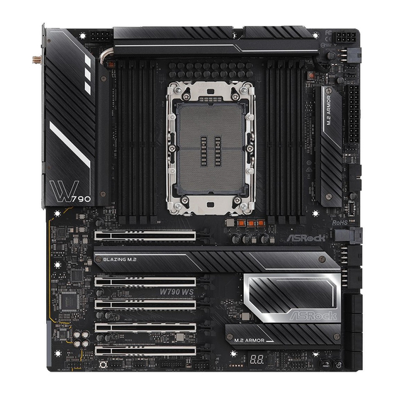
Page 11: Motherboard Layout
W790 WS 1.3 Motherboard Layout ATX12V2 VROC1 BIOS ATX12V1 _FB1 ATX12V3 M2_WIFI_2 CPU_FAN2 /WP_3A USB 3.2 Gen1 T: USB32_1 CPU_FAN1 B: USB32_2 Top: 10GLAN TB_1 (Marvell (Aquantia) AQC113CS ) M2_1 Top: 10GLAN TB_2 (Marvell (Aquantia) AQC113CS ) CHA_FAN1/WP USB 3.2 Gen2 Top: 2.5GLAN... - Page 12 No. Description Virtual RAID On CPU Header (VROC1) 8 pin 12V Power Connector (ATX12V1) 2 x 288-pin DDR5 DIMM Slots (DDR5_B2, DDR5_A2) 2 x 288-pin DDR5 DIMM Slots (DDR5_B1, DDR5_A1) 2 x 288-pin DDR5 DIMM Slots (DDR5_C1, DDR5_D1) 2 x 288-pin DDR5 DIMM Slots (DDR5_C2, DDR5_D2) 8 pin 12V Power Connector (ATX12V2) 6 pin 12V Power Connector (ATX12V3) CPU/Water Pump Fan Connector (CPU_FAN2/WP_3A)
-
Page 13: I/O Panel
W790 WS 1.4 I/O Panel No. Description No. Description 10G LAN RJ-45 Port USB 3.2 Gen1 Type-A Port (USB32_6) ( Marvell (Aquantia) AQC113CS ) * USB 4.0 Thunderbolt 10G LAN RJ-45 Port Type-C Port (TB_2)**** ( Marvell (Aquantia) AQC113CS ) * USB 3.2 Gen1 Type-A Port... - Page 14 Function Line Out Jack Front speaker out (Rear Panel) Pink-Mic Rear speaker out (Front Panel) Microphone Input Jack 5.1ch Central/Subwoofer speaker out (Rear Panel) Lime-Headphone 7.1ch Side Speaker out (Front Panel) ****For the Thunderbolt compatibility and limitation, please visit www.asrock.com.
-
Page 15: Block Diagram
W790 WS 1.5 Block Diagram... -
Page 16: 802.11Ax Wi-Fi 6E Module And Asrock Wifi 2.4/5/6 Ghz Antenna
1.6 802.11ax Wi-Fi 6E Module and ASRock WiFi 2.4/5/6 GHz Antenna 802.11ax Wi-Fi 6E + BT Module This motherboard comes with an exclusive 802.11 a/b/g/n/ac/ax Wi-Fi 6E + BT v5.3 module that offers support for 802.11 a/b/g/n/ac/ax Wi-Fi 6E connectivity standards and Bluetooth v5.3. -
Page 17: Chapter 2 Installation
W790 WS Chapter 2 Installation This is an EATX form factor motherboard. Before you install the motherboard, study the configuration of your chassis to ensure that the motherboard fits into it. Pre-installation Precautions Take note of the following precautions before you install motherboard components or change any motherboard settings. -
Page 18: Installing The Cpu And Heatsink
2.1 Installing the CPU and Heatsink Socket Dust Cover CPU Carrier... - Page 19 W790 WS...
- Page 21 W790 WS CPU Carrier...
- Page 22 Heatsink CPU Carrier Socket...
- Page 23 W790 WS...
-
Page 24: Installing Memory Modules (Dimm)
2.2 Installing Memory Modules (DIMM) This motherboard provides eight 288-pin DDR5 (Double Data Rate 5) DIMM slots in two groups, and supports Quad Channel Memory Technology. 1. For eight channel configuration, you always need to install identical (the same brand, speed, size and chip-type) DDR5 DIMM pairs. - Page 25 W790 WS...
-
Page 26: Connecting The Front Panel Header
2.3 Connecting the Front Panel Header Front Panel Wires System Panel Header Power SW (-) RESET SW (+) Power SW (+) RESET SW (-) Power LED (-) HDD LED (-) Power LED (+) HDD LED (+) PANEL1... -
Page 27: Installing The Motherboard
W790 WS 2.4 Installing the Motherboard... -
Page 28: Installing Sata Drives
2.5 Installing SATA Drives Optical Drive SATA Drive SATA Data Cable... - Page 29 W790 WS SATA Power Connector SATA Data Connector...
-
Page 30: Installing A Graphics Card
2.6 Installing a Graphics Card CLICK! - Page 31 W790 WS Expansion Slots (PCIe Slots) There are 5 PCI Express slots on the motherboard. Before installing an expansion card, please make sure that the power supply is switched off or the power cord is unplugged. Please read the documentation of the expansion card and make necessary hardware settings for the card before you start the installation.
-
Page 32: Connecting Peripheral Devices
2.7 Connecting Peripheral Devices... -
Page 33: Connecting The Power Connectors
W790 WS 2.8 Connecting the Power Connectors... -
Page 34: Power On
2.9 Power On... -
Page 35: Jumpers Setup
W790 WS 2.10 Jumpers Setup The illustration shows how jumpers are setup. When the jumper cap is placed on the pins, the jumper is “Short”. If no jumper cap is placed on the pins, the jumper is “Open”. Clear CMOS Jumper (CLRMOS1) (see p.7, No. -
Page 36: Onboard Headers And Connectors
2.11 Onboard Headers and Connectors Onboard headers and connectors are NOT jumpers. Do NOT place jumper caps over these headers and connectors. Placing jumper caps over the headers and connectors will cause permanent damage to the motherboard. System Panel Header (9-pin PANEL1) (see p.7, No. - Page 37 W790 WS Chassis Intrusion and Speaker Header (7-pin SPK_CI1) (see p.7, No. 25) Please connect the chassis intrusion and the chassis speaker to this header. SPK_CI1 SPEAKER DUMMY DUMMY SIGNAL DUMMY...
- Page 38 Serial ATA3 Connectors Right Angle: (SATA3_0) (see p.7, No. 21)(Upper) (SATA3_1) (see p.7, No. 21)(Lower) (SATA3_2) (see p.7, No. 20)(Upper) (SATA3_3) (see p.7, No. 20)(Lower) (SATA3_4) (see p.7, No. 19)(Upper) (SATA3_5) (see p.7, No. 19)(Lower) (SATA3_6) (see p.7, No. 18)(Upper) (SATA3_7) (see p.7, No.
- Page 39 W790 WS USB 2.0 Headers (9-pin USB_1_2) (see p.7, No. 28) (5-pin USB_3) (see p.7, No. 27) There are two headers on this motherboard. USB_3 P- P+ USB_PWR USB_1_2 USB_PWR DUMMY USB_PWR...
- Page 40 USB 3.2 Gen1 Headers Right Angle: (19-pin USB32_7_8) (see p.7, No. 13) Vertical: (19-pin USB32_9_10) (see p.7, No. 29) There are two headers on this motherboard. Each USB 3.2 Gen1 header can support two ports. USB32_7_8 Dummy IntA_PA_D+ IntA_PB_D+ IntA_PA_D- IntA_PB_D- IntA_PA_SSTX+ IntA_PB_SSTX+...
- Page 41 W790 WS Front Panel Type C USB 3.2 Gen2x2 Header (20-pin USB32_TC1) (see p.7, No. 14) There is one Front Panel Type C USB 3.2 Gen2x2 Header on this motherboard. This header is used for connecting a USB 3.2 Gen2x2 module for additional USB 3.2 Gen2x2 ports.
- Page 42 Front Panel Audio Header (9-pin HD_AUDIO1) (see p.7, No. 34) This header is for connecting audio devices to the front audio panel. HD_AUDIO1 PRESENCE# MIC_RET OUT_RET OUT2_L J_SENSE OUT2_R MIC2_R MIC2_L High Definition Audio supports Jack Sensing, but the panel wire on the chassis must sup- port HDA to function correctly.
- Page 43 W790 WS Chassis/Water Pump Fan Connectors (4-pin CHA_FAN1/WP) (see p.7, No. 12) (4-pin CHA_FAN2/WP) (see p.7, No. 30) (4-pin CHA_FAN3/WP) (see p.7, No. 31) This motherboard provides three 4-Pin water cooling chassis fan connectors. If you plan to connect a 3-Pin chassis water cooler fan, please connect it to Pin 1-3.
- Page 44 CPU Fan Connector (4-pin CPU_FAN1) (see p.7, No. 10) This motherboard provides a 4-Pin CPU fan (Quiet Fan) connector. If you plan to connect a 3-Pin CPU fan, please connect it to Pin 1-3. CPU_FAN1 +12V CPU_F AN_SPEED FAN_SPEED_CONTROL CPU/Water Pump Fan Connector (4-pin CPU_FAN2/WP_3A) (see p.7, No.9) This motherboard provides a 4-Pin water cooling CPU fan connector.
- Page 45 W790 WS ATX Power Connector (24-pin ATXPWR1) (see p.7, No. 11) This motherboard provides a 24-pin ATX power connector. To use a 20-pin ATX power supply, please plug it along Pin 1 and Pin 13. ATXPWR1...
- Page 46 8-pin ATX 12V Power Connectors (8-pin ATX12V1) (see p.7, No. 2) (8-pin ATX12V2) (see p.7, No. 7) This motherboard provides two 8-pin ATX 12V power connectors. To use a 4-pin ATX power supply, please plug it along Pin 1 and Pin 5. *Connecting an ATX 12V 8-pin cable to ATX12V2 is optional.
- Page 47 W790 WS 6-pin ATX 12V Power Connector Right Angle: (6-pin ATX12V3) (see p.7, No. 8) This motherboard provides a 6-pin ATX 12V power connector. To use a 4-pin ATX power supply, please plug it along Pin 1 and Pin 5.
- Page 48 Graphics 12V Power Connectors Right Angle: (8-pin GFX_12V1) (see p.7, No. 16) (8-pin GFX_12V2 (see p.7, No. 17) This motherboard provides two Graphics 12V 8 pin Power Connectors. * Be sure to install the PSU’s power cable to this connector when PCIe card is installed.
- Page 49 W790 WS SPI TPM Header (13-pin SPI_TPM_J1) (see p.7, No. 26) This connector supports SPI Trusted Platform Module (TPM) system, which can securely store keys, digital certificates, passwords, and data. A TPM system also helps enhance network security, protects digital identities, and ensures platform integrity.
- Page 50 U.2 Connector Right Angle: (36-pin U2_1) (see p.7, No. 15) This connector supports U.2 NVM Express storage devices up to Gen4x4 (64 Gb/s). U2_1...
- Page 51 W790 WS Virtual RAID On CPU Header (4-pin VROC1) (see p.7, No. 1) This connector supports Intel® Virtual RAID on CPU and NVME/AHCI RAID on CPU PCIE. VROC1 +3VSB VROC RAID KEY With the introduction of the Intel VROC product, there are three modes of operation:...
-
Page 52: Smart Buttons
2.12 Smart Buttons The motherboard has four smart buttons: Power Button, Reset Button, Clear CMOS Button and BIOS Flashback Button, allowing users to quickly turn on/off the system, reset the system, clear the CMOS values or flash the BIOS. Power Button (PWRBTN1) (see p.7, No. - Page 53 W790 WS Clear CMOS Button (CLRCBTN1) (see p.7, No. 32) Clear CMOS Button allows users to quickly clear the CMOS values. CLRCBTN1 This function is workable only when you power off your computer and unplug the power supply.
- Page 54 BIOS Flashback Button (BIOS_FB1) (see p.9, No. 14) BIOS Flashback Button allows users to flash the BIOS. BIOS_FB1 USB BIOS Flashback port...
- Page 55 W790 WS ASRock BIOS Flashback feature allows you to update BIOS without powering on the system, even without CPU. Before using the BIOS Flashback function, please suspend BitLocker and any encryption or security relying on the TPM. Make sure that you have already stored and backup-ed the recovery key.
-
Page 56: Dr. Debug
2.13 Dr. Debug Dr. Debug is used to provide code information, which makes troubleshooting even easier. Please see the diagrams below for reading the Dr. Debug codes. Code Description 0x10 PEI_CORE_STARTED 0x11 PEI_CAR_CPU_INIT 0x15 PEI_CAR_NB_INIT 0x19 PEI_CAR_SB_INIT 0x31 PEI_MEMORY_INSTALLED 0x32 PEI_CPU_INIT 0x33 PEI_CPU_CACHE_INIT... - Page 57 W790 WS 0x63 DXE_CPU_INIT 0x68 DXE_NB_HB_INIT 0x69 DXE_NB_INIT 0x6A DXE_NB_SMM_INIT 0x70 DXE_SB_INIT 0x71 DXE_SB_SMM_INIT 0x72 DXE_SB_DEVICES_INIT 0x78 DXE_ACPI_INIT 0x79 DXE_CSM_INIT 0x90 DXE_BDS_STARTED 0x91 DXE_BDS_CONNECT_DRIVERS 0x92 DXE_PCI_BUS_BEGIN 0x93 DXE_PCI_BUS_HPC_INIT 0x94 DXE_PCI_BUS_ENUM 0x95 DXE_PCI_BUS_REQUEST_RESOURCES 0x96 DXE_PCI_BUS_ASSIGN_RESOURCES 0x97 DXE_CON_OUT_CONNECT 0x98 DXE_CON_IN_CONNECT...
- Page 58 0x99 DXE_SIO_INIT 0x9A DXE_USB_BEGIN 0x9B DXE_USB_RESET 0x9C DXE_USB_DETECT 0x9D DXE_USB_ENABLE 0xA0 DXE_IDE_BEGIN 0xA1 DXE_IDE_RESET 0xA2 DXE_IDE_DETECT 0xA3 DXE_IDE_ENABLE 0xA4 DXE_SCSI_BEGIN 0xA5 DXE_SCSI_RESET 0xA6 DXE_SCSI_DETECT 0xA7 DXE_SCSI_ENABLE 0xA8 DXE_SETUP_VERIFYING_PASSWORD 0xA9 DXE_SETUP_START 0xAB DXE_SETUP_INPUT_WAIT 0xAD DXE_READY_TO_BOOT 0xAE DXE_LEGACY_BOOT...
- Page 59 W790 WS 0xAF DXE_EXIT_BOOT_SERVICES 0xB0 RT_SET_VIRTUAL_ADDRESS_MAP_BEGIN 0xB1 RT_SET_VIRTUAL_ADDRESS_MAP_END 0xB2 DXE_LEGACY_OPROM_INIT 0xB3 DXE_RESET_SYSTEM 0xB4 DXE_USB_HOTPLUG 0xB5 DXE_PCI_BUS_HOTPLUG 0xB6 DXE_NVRAM_CLEANUP 0xB7 DXE_CONFIGURATION_RESET 0xF0 PEI_RECOVERY_AUTO 0xF1 PEI_RECOVERY_USER 0xF2 PEI_RECOVERY_STARTED 0xF3 PEI_RECOVERY_CAPSULE_FOUND 0xF4 PEI_RECOVERY_CAPSULE_LOADED 0xE0 PEI_S3_STARTED 0xE1 PEI_S3_BOOT_SCRIPT 0xE2 PEI_S3_VIDEO_REPOST...
- Page 60 0xE3 PEI_S3_OS_WAKE 0x50 PEI_MEMORY_INVALID_TYPE 0x53 PEI_MEMORY_NOT_DETECTED 0x55 PEI_MEMORY_NOT_INSTALLED 0x57 PEI_CPU_MISMATCH 0x58 PEI_CPU_SELF_TEST_FAILED 0x59 PEI_CPU_NO_MICROCODE 0x5A PEI_CPU_ERROR 0x5B PEI_RESET_NOT_AVAILABLE 0xD0 DXE_CPU_ERROR 0xD1 DXE_NB_ERROR 0xD2 DXE_SB_ERROR 0xD3 DXE_ARCH_PROTOCOL_NOT_AVAILABLE 0xD4 DXE_PCI_BUS_OUT_OF_RESOURCES 0xD5 DXE_LEGACY_OPROM_NO_SPACE 0xD6 DXE_NO_CON_OUT 0xD7 DXE_NO_CON_IN...
- Page 61 W790 WS 0xD8 DXE_INVALID_PASSWORD 0xD9 DXE_BOOT_OPTION_LOAD_ERROR 0xDA DXE_BOOT_OPTION_FAILED 0xDB DXE_FLASH_UPDATE_FAILED 0xDC DXE_RESET_NOT_AVAILABLE 0xE8 PEI_MEMORY_S3_RESUME_FAILED 0xE9 PEI_S3_RESUME_PPI_NOT_FOUND 0xEA PEI_S3_BOOT_SCRIPT_ERROR 0xEB PEI_S3_OS_WAKE_ERROR...
- Page 62 2.14 M.2 SSD Module Installation Guide (M2_1) The M.2 is a small size and versatile card edge connector that aims to replace mPCIe and mSATA. The Blazing M.2 Socket (M2_1, Key M) supports type 2230/2242/2260/2280 PCIe Gen5x4 (128 Gb/s) mode. Installing the M.2 SSD Module Step 1 Prepare a M.2 SSD module and the...
- Page 63 W790 WS Step 3 Before installing a M.2 SSD module, please loosen the screws to remove the M.2 heatsink. *Please remove the protective films on the bottom side of the M.2 heatsink before you install a M.2 SSD module. Step 4 Prepare the M.2 standoff that comes...
- Page 64 Step 6 Before securing the M.2 heatsink, make sure to align the notch on the SSD to the standoff on the motherboard if you use a Type 2280 SSD module; otherwise, the SSD module may be damaged. *The illustrations here are for reference only.
- Page 65 W790 WS Step 7 Tighten the screw with a screwdriver to secure the M.2 heatsink into place in the order shown. Tighten screw opposite the M.2 connector first (2), and then tighten the one next to the M.2 connector (3).
- Page 66 2.15 M.2_SSD (NGFF) Module Installation Guide (M2_2 and M2_3) The M.2 is a small size and versatile card edge connector that aims to replace mPCIe and mSATA. The Blazing M.2 Sockets (M2_2 and M2_3, Key M) support type 2260/2280 PCIe Gen5x4 (128 Gb/s) mode .
- Page 67 W790 WS Step 3 Before installing a M.2 SSD module, please loosen the screws to remove the M.2 heatsink. *Please remove the protective films on the bottom side of the M.2 heatsink before you install a M.2 SSD module. Step 4 Move the standoff based on the module type and length.
- Page 68 Tighten the screw with a screwdriver to secure the M.2 heatsink into place. Please do not overtighten the screw as this might damage the M.2 heatsink. For the latest updates of M.2 SSD module support list, please visit our website for details: http://www.asrock.com...
- Page 69 W790 WS 2.16 M.2_SSD (NGFF) Module Installation Guide (M2_4) The M.2, also known as the Next Generation Form Factor (NGFF), is a small size and versatile card edge connector that aims to replace mPCIe and mSATA. The Blazing M.2 Socket (M2_4, Key M) supports type 2260/2280 PCIe Gen5x4 (128 Gb/s) mode.
- Page 70 Step 3 Before installing a M.2 SSD module, please loosen the screws to remove the M.2 heatsink. *Please remove the protective films on the bottom side of the M.2 heatsink before you install a M.2 SSD module. Step 4 Peel off the yellow protective film on the nut A.
- Page 71 W790 WS Step 6 Tighten the screw with a screwdriver to secure the module into place. Please do not overtighten the screw as this might damage the module. NUT2 NUT1 Skip Step 6 if your M.2 SSD module is Type 2280.
- Page 72 M.2 connector (3). *Please do not overtighten the screw as this might damage the module and M.2 heatsink. For the latest updates of M.2 SSD module support list, please visit our website for details: http://www.asrock.com...
- Page 73 (including damages for loss of profits, loss of business, loss of data, interruption of business and the like), even if ASRock has been advised of the possibility of such damages arising from any defect or error in the documentation or product.
- Page 74 INTEL END USER SOFTWARE LICENSE AGREEMENT IMPORTANT - READ BEFORE COPYING, INSTALLING OR USING. LICENSE. Licensee has a license under Intel’s copyrights to reproduce Intel’s Software only in its unmodified and binary form, (with the accompanying documentation, the “Software”) for Licensee’s personal use only, and not commercial use, in connection with Intel-based products for which the Software has been provided, subject to the following conditions: (a) Licensee may not disclose, distribute or transfer any part of the Software, and You agree...
- Page 75 U.S. GOVERNMENT RESTRICTED RIGHTS. The Software is a commercial item (as defined in 48 C.F.R. 2.101) consisting of commercial computer software and commercial computer software documentation (as those terms are used in 48 C.F.R. 12.212), consistent with 48 C.F.R. 12.212 and 48 C.F.R 227.7202-1 through 227.7202-4. You will not provide the Software to the U.S.
- Page 76 If you require assistance please call ASRock Tel : +886-2-28965588 ext.123 (Standard International call charges apply)
- Page 77 ASRock follows the green design concept to design and manufacture our products, and makes sure that each stage of the product life cycle of ASRock product is in line with global environmental regulations. In addition, ASRock disclose the relevant information based on regulation requirements.
- Page 78 Operations in the 5.15-5.35GHz band are restricted to indoor usage only. Radio transmit power per transceiver type Function Frequency Maximum Output Power (EIRP) 2400-2483.5 MHz 18.5 + / -1.5 dbm 5150-5250 MHz 21.5 + / -1.5 dbm 18.5 + / -1.5 dbm (no TPC) 5250-5350 MHz 21.5 + / -1.5 dbm (TPC) WiFi...
Need help?
Do you have a question about the W790 WS and is the answer not in the manual?
Questions and answers