Advertisement
Quick Links
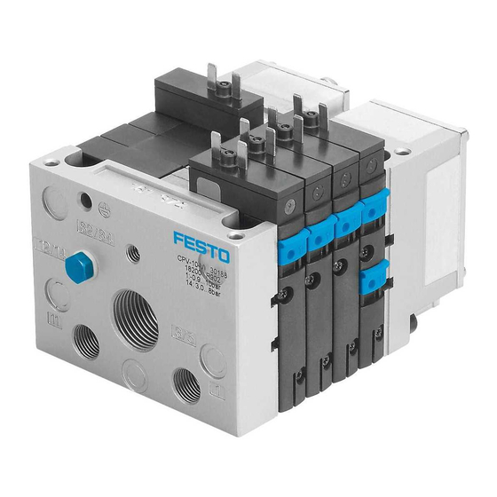
CPV10-EX-VI
Valve terminal
Addendum document | Operating conditions EX
8141984
202102e
[8141986]
Translation of the original instructions
© 2021 all rights reserved to Festo SE & Co. KG
1
Identification EX
Identification mark
IECEx
Ex ib IIC T4 Gb
Ex ib IIIC T100°C Db
ATEX
II 2G Ex ib IIC T4 Gb
II 2D Ex ib IIIC T100 ° C Db
China
Ex ib IIC T4 Gb
Ex ex ibD 21 T100
Tab. 1 Identification EX
2
Applicable documents
NOTICE!
Technical data for the product can have different values in other documents. For
operation in an explosive atmosphere, the technical data in this document always
have priority.
All available documents for the product è www.festo.com/sp.
3
Safety
3.1
General safety instructions
–
The device can be used under the stated operating conditions in zones 1 and
2, explosive gas atmospheres, and in zones 21 and 22, explosive dust atmo
spheres.
–
Use the device in its original status without any unauthorised modifications.
–
The device may only be used in the delivered configuration in a potentially
explosive atmosphere.
–
Operate the device only with compressed air of at least quality class [7:4:4] in
accordance with ISO 85731:2010.
–
Always generate compressed air outside the potentially explosive area.
–
Use only plug sockets KMYZ4 ... BEX for the electrical connection.
–
Connect valve plates to a certified intrinsically safe circuit Ex ia IIC or ib IIC in
accordance with the operating conditions.
3.2
Intended use
The valve terminal controls pneumatic actuators as intended. The intrinsically safe
solenoid coils control the individual valve plates of the valve terminal.
3.3
Identification X: special conditions
–
U
= 32 V DC; I
= 0.2 A; P
= 0.76 W
i
i
i
–
Ambient temperature 5 °C £ Ta £ +50 °C.
–
At ambient temperatures up to max. +40 °C the valve terminal can be oper
ated with higher performance characteristics (è 8 Technical data).
–
Conversion and replacement of valve plates is permissible.
–
Use only approved accessories è www.festo.com/catalogue.
–
Install electrical plug connectors protected against electric shock.
4
Function
The valve terminal is a configurable functional unit for controlling pneumatic drive
systems. The valve terminal includes a. valve plates with 5/2, 3/2or
2/2way valves. Switching on the voltage energises the solenoid coil and the
valve is actuated.
Festo SE & Co. KG
Ruiter Straße 82
73734 Esslingen
Germany
+49 711 3470
www.festo.com
8141984
Certificate
IECEx IBE 13.0046X
IBExU 12ATEX 1110X
GYJ20.1646X
5
Assembly
5.1
Mechanical
NOTICE!
Installation and commissioning may only be performed in accordance with the
operating instructions and by qualified personnel.
–
Allow dissipation of selfheating. The device surface of the solenoid coil must
not be covered.
–
Ensure that surfaces to be cleaned can be easily accessed.
5.2
Pneumatic
–
Seal unused openings in outlets 12 and 14 (pilot air) as well as 82 and 84
(exhaust air) with blanking plugs.
5.3
Electrical
WARNING!
Switching the connections will result in loss of intrinsic safety.
•
Pay attention to the correct polarity of the plug socket
The electrical connection is established via 2pin pushin connectors on each indi
vidual solenoid coil. A plug socket KMYZ4 ... BEX is required for this.
Pin
Function
–
0 V DC
+
£ 32 V DC or £36 V DC
1) Colour code in accordance with IEC 60575:198301
Tab. 2 Pin allocation for solenoid coils
Fig. 1
6
Commissioning
WARNING!
The discharge of electrostatically charged parts can lead to ignitable sparks.
•
Prevent electrostatic charging by taking appropriate installation and cleaning
measures.
•
Include the device in the system's potential equalisation. The surface coating
of the solenoid valves is electrically nonconductive.
•
Prevent processes that are chargegenerating.
–
Observe the specifications on the product labelling.
–
Observe operating conditions
7
Maintenance and care
–
The product is maintenancefree if used as intended.
–
Check function of the product regularly.
–
If there is audible leakage: check the fitting of the connections or replace the
affected valve circuits.
The replacement of wearing and spare parts is possible in individual cases.
Repairs of this type must only be carried out by trained and authorised special
ists.
–
Please contact your Festo technical consultant.
8
Technical data
General operating conditions
Operating pressure with
[bar]
external pilot pressure
Operating pressure with
[bar]
internal pilot pressure
Ambient temperature
[°C]
Temperature of medium
[°C]
Operating medium
Mounting position
Colour code
1)
BU
BUWH
0 ... 10
3 ... 8
–5 ... +50
–5 ... +50
Compressed air in accordance with
ISO 85731:2010:[7:4:4]
any
Advertisement

Subscribe to Our Youtube Channel
Related Manuals for Festo CPV10-EX-VI


Summary of Contents for Festo CPV10-EX-VI
- Page 1 0 V DC Translation of the original instructions £ 32 V DC or £36 V DC BUWH © 2021 all rights reserved to Festo SE & Co. KG 1) Colour code in accordance with IEC 60575:198301 Tab. 2 Pin allocation for solenoid coils Identification EX...
- Page 2 General operating conditions Tightening torque Wall bracket, Hrail [Nm] Pneumatic multiple connect [Nm] or plate – valve terminal Earthing screw [Nm] Tie rod [Nm] Flat plate silencer on end [Nm] 1.0 ±10 % plate Plug socket [Nm] 0.3 ±55 % Electrical connection KMYZ40.5BEX –...
Need help?
Do you have a question about the CPV10-EX-VI and is the answer not in the manual?
Questions and answers