Table of Contents
Advertisement
Advanced Test Equipment Corp.
www.atecorp.com 800-404-ATEC (2832)
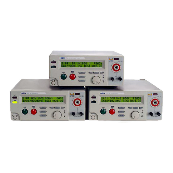
V60 Series Electrical Safety Testers
Operating Manual
For all Models V60, V61, and V63
9880A Via Pasar, San Diego CA 92126 USA
V: (858)689-2755
F: (858)689-2760
Web:
www.vitrek.com
E-mail:
info@vitrek.com
Copyright Vitrek Corporation 2000-05, all rights reserved,
rev 6/10/2005
Advertisement
Table of Contents

Subscribe to Our Youtube Channel
Related Manuals for ATE Vitrek V60 Series


Summary of Contents for ATE Vitrek V60 Series
- Page 1 Advanced Test Equipment Corp. www.atecorp.com 800-404-ATEC (2832) V60 Series Electrical Safety Testers Operating Manual For all Models V60, V61, and V63 9880A Via Pasar, San Diego CA 92126 USA V: (858)689-2755 F: (858)689-2760 Web: www.vitrek.com E-mail: info@vitrek.com Copyright Vitrek Corporation 2000-05, all rights reserved, rev 6/10/2005...
- Page 2 Vitrek V60 Series – Electrical Safety Tester USER MANUAL...
- Page 3 Vitrek V60 Series – Electrical Safety Tester USER MANUAL WARNING Vitrek Corporation, its representatives, vendors, and distributors assume no liability for the operation of this instrument in an unsafe manner. This instrument generates and delivers hazardous voltages (up to 5KVAC / 6KVDC). Always be extremely careful when using this instrument or any high voltage device.
-
Page 4: Table Of Contents
Vitrek V60 Series – Electrical Safety Tester USER MANUAL TABLE OF CONTENTS PAGE 1. INTRODUCTION to V60 SERIES.......... 1-1. Description…………………………..…………………… 1-2. Features...…………………………..………………….…. 2. SPECIFICATIONS………………………………………….. 3. PRECAUTIONS BEFORE OPERATION……...…………... 3-1. Unpacking the Instrument……..…………….………….. 3-2. Safety Notice………………..…………………..………... 3-3. Environment……………………………………..………. 4. PANEL INTRODUCTION……………………..……………. -
Page 5: Description
(Hipot) testing on a wide variety of electrical equipment and components. The Vitrek V60 series is a family of four automatic voltage withstand testers. The functions they provide include AC Hipot, DC Hipot, Insulation Resistance plus continuity. -
Page 6: Features
Vitrek V60 Series – Electrical Safety Tester USER MANUAL 1-2. Features The V60 series electrical safety testers offer many outstanding features: 1) No load setup of trip current and output voltage. A safe way to setup the trip current and output voltage is without the high voltage being activated. -
Page 7: Specifications
Vitrek V60 Series – Electrical Safety Tester USER MANUAL 2. 2. VITREK V60 SERIES SAFETY TESTER SPECIFICATIONS 1) AC Hi-Pot Specifications: Voltage Range 0.100~5.000Kv Voltage Step 5V/step Voltage Regulation 1% + 5V (line & load) Voltage Accuracy 1% of reading +10V Current Sourcing*... - Page 8 Vitrek V60 Series – Electrical Safety Tester USER MANUAL 7) Storage Groups Steps 8) Interface RS-232 Standard GPIB Option 9) PLC Control D-sub 9 pins female Standard 10) Scanner Interface D-sub 9 pins female Standard 11) General Power Source AC100V, 120V, 220V, 230V±10% 50/60Hz Indoor use, altitude up to 2000m.
- Page 9 Vitrek V60 Series – Electrical Safety Tester USER MANUAL Accessories: NIST certification, TL-20-60 Test Leads, Instruction Manual and power cord Accuracy: Stated specifications apply for 1 year at 23 °C ± 5 °C Calibration: Certificate of calibration, traceable to NIST provided Compliance: CE mark certified to EN61010 and EMC directives EN50081-1 &...
-
Page 10: Precautions Before Operation
Vitrek V60 Series – Electrical Safety Tester USER MANUAL 3. PRECAUTIONS BEFORE OPERATION 3-1. Unpacking the instrument The product has been fully inspected and tested before shipping from the factory. Upon receiving the instrument, please unpack and inspect it for any damage that may have occurred during transportation. If any sign of damage is found, notify the carrier and Vitrek or your distributor immediately. -
Page 11: Environment
Vitrek V60 Series – Electrical Safety Tester USER MANUAL alligator test leads while high voltage is applied. Also, when using the optional HV probe do not touch the exposed conductive tip of the test probe during testing. Provide full control the power supplied to the tester by means of a carefully placed on/off switch or remote power control device. -
Page 12: Panel Introduction
Vitrek V60 Series – Electrical Safety Tester USER MANUAL 4. PANEL INTRODUCTION 4-1. Front Panel FAIL CAUTION HIGH VOLTAGE 5.0 KVAC MAX. 6.0 KVDC MAX. PASS START RESET MENU FIELD EDIT/SAVE POWER UTILITY CONTI.CHECK RETURN 15 16 Model Number Model number and description... -
Page 13: Rear Panel
Vitrek V60 Series – Electrical Safety Tester USER MANUAL 4-2. Rear Panel Ground Terminal Connect Ground terminal to the earth ground. Fuse Holder with To change AC source voltage, pull the fuse holder and Voltage Selector rotate it to the proper value. -
Page 14: Main Lcd Display
Vitrek V60 Series – Electrical Safety Tester USER MANUAL 5. OPERATING THE INSTRUMENT 5-1. Main Display LCD Storage Mode Output Voltage/Current Status 1 : 1 A C W V = 5 . 0 0 0 k V R E A D Y I m A x = 0 1 . - Page 15 Vitrek V60 Series – Electrical Safety Tester USER MANUAL 5-2. Preparing the V60 Series EST for Use To view the Stored Steps 1. Press the MENU key to access test number field. M E N U MENU 2. Use the left and right arrow keys to select group or step. Use the knob to change the active step.
- Page 16 Vitrek V60 Series – Electrical Safety Tester USER MANUAL 3. Use the knob to adjust the parameter. Use arrow keys to change the knob’s resolution. A C W 4. Use FIELD key to advance to the next parameter field. V = 2 . 0 0 0 k V FIELD 5.
- Page 17 Vitrek V60 Series – Electrical Safety Tester USER MANUAL To Begin a Group Test 1. Repeat the procedure “To View the Stored Steps” to select a step. 2. Press RESET button to enter status READY. R E A D Y RESET 3.
- Page 18 Vitrek V60 Series – Electrical Safety Tester USER MANUAL 7. If the result is fail, the FAIL LED will be active and the buzzer will alarm the operator. To stop the alarm, press RESET button again. F A I L RESET 8.
- Page 19 Vitrek V60 Series – Electrical Safety Tester USER MANUAL Table of system utility: Parameter Option Description The group test procedure always begins from step 1 to end of From STEP 1 group. (e.g. 3:1~3:6, 4:1~4:6) TEST MODE The group test procedure always begins from the step selected From the present step to end of group.
- Page 20 Vitrek V60 Series – Electrical Safety Tester USER MANUAL To Edit/Save the System Utility 1. Follow the above procedure “To View the System Utility “ to select a parameter. 2. Press the EDIT/SAVE key to enter EDIT mode. E D I T EDIT/SAVE 3.
- Page 21 Vitrek V60 Series – Electrical Safety Tester USER MANUAL 5-3. Structure of Test Sequence Storage The test sequence database of the EST consists of a total of 6 test sequences or groups (group 1 ~ group 6), with 6 steps (step 1 ~ step 6) for each group. In addition to these steps, there is another step “0:0” for manually controlled tests.
-
Page 22: Menu Parameter Setup & Operation
Vitrek V60 Series – Electrical Safety Tester USER MANUAL 5-4. Menu Parameter Setup AC/DC Hipot - Voltage withstand test (ACW/DCW) Press MENU key to enter MENU mode then use knob and arrow keys to select a step. Press EDIT/SAVE key to enter EDIT mode. The cursor stays at the “test mode” field. Use knob to select desired test ACW (DCW). - Page 23 Vitrek V60 Series – Electrical Safety Tester USER MANUAL Insulation Resistance test (IR) Press MENU key to enter status MENU then use the knob and Arrow keys to select a step. Press EDIT/SAVE key to enter status EDIT. Now the cursor stays at the “test mode”...
- Page 24 Vitrek V60 Series – Electrical Safety Tester USER MANUAL Continuity Check (Cont.) Press MENU key to enter status MENU then use the knob and arrow keys to select a step. Press EDIT/SAVE key to enter status EDIT. Now the cursor stays at the “test mode” field. Use the knob to select mode Cnt.
-
Page 25: Remote Interface Operation
Vitrek V60 Series – Electrical Safety Tester USER MANUAL 5-5 Remote Interface Operation To prepare the unit for control via the remote interface, press the UTILITY key and dial up the TEST CONTROL MODE using the knob. Press the SAVE/EDIT key to edit the field and use the knob to select MODE 3: PLC ENABLE, then press SAVE/EDIT to save the setting and press MENU to exit the utility mode. -
Page 26: Measurement Connections
Vitrek V60 Series – Electrical Safety Tester USER MANUAL 6. MEASUREMENT CONNECTIONS 1. High Voltage Output Terminal. This large HV connector with a red circle around it is the output terminal for all HV tests (ACW, DCW and IR). For typical electrical safety testing, this terminal connects to both the line and neutral power pins of the device under test (DUT). - Page 27 Vitrek V60 Series – Electrical Safety Tester USER MANUAL 4. Device Under Test (DUT). A power supply shown here, represents a typical DUT. The connection to the DUT power inlet is made here by way of the optional TL-IEC-60. 5. DUT Chassis. The Conti Check terminal connects directly to the DUT chassis via the standard alligator test lead.
-
Page 28: Programming
7. PROGRAMMING 7-1. Introduction The Vitrek V60 Series Electrical Safety Tester (EST) is a fully interactive automatic measurement system. Communication between the V60 Series and host computers is easily accomplished. The V60 Series’ standard RS232 interface or optional GPIB interface provide the capability to download and run a custom test sequence, as well as, monitor the status of the test and retrieve results and actual readings. - Page 29 Vitrek V60 Series – Electrical Safety Tester USER MANUAL Do not use loop or parallel structure for the topology of GPIB system. Computer’s Connection A personal computer with a GPIB card is the essential facilities in order to operate the V60 Series via GPIB interface.
- Page 30 Vitrek V60 Series – Electrical Safety Tester USER MANUAL 7-3. Connecting the V60 Series via the RS232 Interface The RS232 interface capabilities: The RS232 interface provides a point-to-point connection between two items of equipment such as a computer and the EST. There are some parameters you need to set on the both sides. Once you have set these parameters, you can control the power supply through the RS232 interface.
-
Page 31: Input And Output Queue
Vitrek V60 Series – Electrical Safety Tester USER MANUAL Wiring configurations for DB9 to DB9: EQUIPMENT COMPUTER (DB9, DTE) (DB9, DTE) Pin2 Pin2 Pin3 Pin3 Pin5 Pin5 Computer’s Connection A personal computer with a COM port is the essential facilities in order to operate the V60 Series via RS232 interface. - Page 32 Vitrek V60 Series – Electrical Safety Tester USER MANUAL syntax has been adopted by SCPI to provide common commands for the identical functions of different programmable instruments. SCPI Common Command & Queries Syntax & Status Data Structure Interface Function SCPI IEEE-488.1...
- Page 33 Vitrek V60 Series – Electrical Safety Tester USER MANUAL Root node :SYSTem Lower-level node :ERRor :AUTO Leaf Node :STATe :STARt :CYCLe Figure 4: Tree hierarchy The command header is configured by header path and leaf node. Figure 5 shows the command header for the leaf node indicated in Figure 4.
- Page 34 Vitrek V60 Series – Electrical Safety Tester USER MANUAL Table 1 defines the Boolean and other parameter types for the V60 Series. Parameter Type Description Example 0, 1 Boolean Boolean numbers or values Integers 0, 1, 18 Decimal numbers 1.5, 3.141, 8.4 Floating point numbers 4.5E-1, 8.25E+1...
- Page 35 Vitrek V60 Series – Electrical Safety Tester USER MANUAL Combining Commands You can use a semicolon (;) to combine commands. But continuously query command will cause message missing. For example :GRO:STEP: ACWS:VOLT:;CMAX? If the command that follows the semicolon has a different header path from the root level, you must use a colon to force a return to the root level.
- Page 36 Vitrek V60 Series – Electrical Safety Tester USER MANUAL :UTILity:ARC:CURRent? Query the value of ARC current :UTILity:ARC:MODe <NR1> Set the ARC test mode :UTILity:ARC:MODe? Query the ARC test mode :UTILity:TEST:MODe <NR1> Set the test mode from step 1 or form present setp...
- Page 37 Vitrek V60 Series – Electrical Safety Tester USER MANUAL :DCWStanding:CMINimum <NR2> Set the DCW test minimum current :DCWStanding:CMINimum? Query the DCW test minimum current :DCWStanding:CMAXimum <NR2> Set the DCW test maximum current :DCWStanding:CMAXimum? Query the DCW test maximum current :DCWStanding:RTIMe <NR2>...
- Page 38 Vitrek V60 Series – Electrical Safety Tester USER MANUAL :STATus:OPERation:CONDition ? Returns the contents of the OPERation condition register. Returns NR1. :STATus:OPERation:ENABle <NR1> Sets the contents of the enable mask for the OPERation event register. :STATus:OPERation:ENABle ? Returns the contents of the enable mask for the OPERation event register.
-
Page 39: Details Of Command Reference
Vitrek V60 Series – Electrical Safety Tester USER MANUAL 7-6. Details of Command Reference Each command in this chapter will give a detailed description. The examples of each command will be provided and what query form might return. *CLS (no query form) Function: Clear all event status data register. - Page 40 Vitrek V60 Series – Electrical Safety Tester USER MANUAL *IDN? (query only) Function: Return the unique identification code of the EST. Syntax: *IDN? Returns: <string> includes Manufacturer, model number, serial number and firmware version. Examples: *IDN? - returns “Vitrek.Inc, V60, 0, FW1.21”...
- Page 41 Vitrek V60 Series – Electrical Safety Tester USER MANUAL *SAV Function: Save the setting data to a specific memory location. Syntax: *SAV <NR1> <NR1> is in the range from 0 through 99. Examples: *SAV 01 - saves the current setting data to memory location 1.
- Page 42 Vitrek V60 Series – Electrical Safety Tester USER MANUAL *WAI (no query form) Function: WAI prevents the programming instrument from executing further commands or queries until all pending operations are finished. Syntax: *WAI :GROup Function: Set or query the value of group.
- Page 43 Vitrek V60 Series – Electrical Safety Tester USER MANUAL :FUNCtion:TEST:STATe Function: Set or query the test state ( 0.OFF 1. ON 2.CONTINUE) Syntax: :FUNCtion:TEST:STATe <NR1> :FUNCtion:TEST:STATe? <NR1> is in the range from 0 through 2. Return: <NR1> Examples: :FUNCtion:TEST:STATe 1 - start test.
- Page 44 Vitrek V60 Series – Electrical Safety Tester USER MANUAL V/I: Test Function (5 bytes) Unit (2 bytes) CONT HOLD PAUSE Meas: Test Function (5 bytes) Unit (4 bytes) MΩ CONT mΩ HOLD Time: Time (1 byte) Value (5 bytes) Unit (1 byte) Ramp 005.0...
- Page 45 Vitrek V60 Series – Electrical Safety Tester USER MANUAL :UTILity:ARC:CURRent Function: Set or query the ARC current Syntax: :UTILity:ARC:CURRent <NR2> :UTILity:ARC:CURRent? <NR2>Please refer to the specification Return: <NR2> is in the integer range 1 to 40mA Examples: :UTILity:ARC:CURRent 2 - sets the ARC current to 2.00mA.
- Page 46 Vitrek V60 Series – Electrical Safety Tester USER MANUAL :UTILity:IRTest:MODe Function: Set or query the IR test mode ( 0 :Stop on Fail, 1: Stop on Pass, 2: TIMER ) Syntax: :UTILity:IRTest:MODe <NR1> :UTILity:IRTest:MODe? <NR1> is in the range from 0 through 2.
- Page 47 Vitrek V60 Series – Electrical Safety Tester USER MANUAL :ACContinuous:CMAXimum Function: Set or query the CAC test maximum current. Syntax: :ACContinuous:CMAXimum <NR2> :ACContinuous:CMAXimum? <NR2> Please refer to the specification Return: <NR2> Examples: :ACContinuous:CMAXimum 1.00 - sets the CAC test maximum current to 1.00mA.
- Page 48 Vitrek V60 Series – Electrical Safety Tester USER MANUAL :DCContinuous:CMINimum Function: Set or query the CDC test minimum current. Syntax: :DCContinuous:CMINimum <NR2> :DCContinuous:CMINimum? <NR2> Please refer to the specification Return: <NR2> Examples: :DCContinuous:CMINimum 1.00 - sets the CDC test minimum current to 1.00mA.
- Page 49 Vitrek V60 Series – Electrical Safety Tester USER MANUAL :ACWStanding:VOLTage Function: Set or query the ACW test voltage. Syntax: :ACWStanding:VOLTage <NR2> :ACWStanding:VOLTage? <NR2> Please refer to the specification Return: <NR2> Examples: : ACWStanding:VOLTage 1.000 - sets the ACW test voltage to 1.000kV.
- Page 50 Vitrek V60 Series – Electrical Safety Tester USER MANUAL :ACWStanding:RTIMe Function: Set or query the ACW ramp time. Syntax: :ACWStanding:RTIMe <NR2> :ACWStanding:RTIMe? <NR2> Please refer to the specification Return: <NR2> Examples: :ACWStanding:RTIMe 5.0 - sets the ACW ramp time to 5 sec.
- Page 51 Vitrek V60 Series – Electrical Safety Tester USER MANUAL :DCWStanding:CMINimum Function: Set or query the DCW test minimum current. Syntax: :DCWStanding:CMINimum <NR2> :DCWStanding:CMINimum? <NR2> Please refer to the specification Return: <NR2> Examples: :DCWStanding:CMINimum 1.00 - sets the DCW test minimum current to 1.00mA.
- Page 52 Vitrek V60 Series – Electrical Safety Tester USER MANUAL :DCWStanding:TTIMe Function: Set or query the DCW test time. Syntax: :DCWStanding:TTIMe <NR2> :DCWStanding:TTIMe? <NR2> Please refer to the specification Return: <NR2> Examples: :DCWStanding:TTIMe 5.0 - sets the DCW test time to 5 sec.
- Page 53 Vitrek V60 Series – Electrical Safety Tester USER MANUAL :IRESistance:RMAXimum Function: Set or query the IR test maximum resistance. Syntax: :IRESistance:RMAXimum <NR1> :IRESistance:RMAXimum? <NR1> Please refer to the specification Return: <NR1> Examples: :IRESistance:RMAXimum 100 - sets the IR test maximum resistance to 100MΩ.
- Page 54 Vitrek V60 Series – Electrical Safety Tester USER MANUAL :CONTinuity:RMAXimum Function: Set or query the continuity test maximum resistance. Syntax: :CONTinuity:RMAXimum <NR1> :CONTinuity:RMAXimum? <NR1> Please refer to the specification Return: <NR1> Examples: :CONTinuity:RMAXimum 100.0 - sets the continuity test maximum resistance to 100.0mΩ.
-
Page 55: Status And Error Reporting
Vitrek V60 Series – Electrical Safety Tester USER MANUAL 7-7. Status and Error Reporting A set of status registers allows the user to quickly determine the EST’s internal processing status. The status register, as well as the status and event reporting system, adhere to SCPI recommendations. - Page 56 Vitrek V60 Series – Electrical Safety Tester USER MANUAL Figure 8: Status registers and related commands To SBR Event Enable Condition Register Register Register The CONDition register is a read-only register which monitors the present state of the instrument. The CONDition register updates in real time and the inputs are not latched or buffered.
- Page 57 Vitrek V60 Series – Electrical Safety Tester USER MANUAL Status Registers There are two status registers are included to the EST defined by IEEE-488.1 and IEEE-488.2 standards. 1. Status Byte Register (SBR) 2. Standard Event Status Register (SESR) Status Byte Register (SBR): The SBR (Table 6) summarizes the status of all other registers and queues.
- Page 58 Vitrek V60 Series – Electrical Safety Tester USER MANUAL When one of the bits of the enable registers is high and the corresponding bit in the status register is high, the enable registers will perform a logical OR function, the output that controls the set bit of the Status Byte Register is high.
- Page 59 Vitrek V60 Series – Electrical Safety Tester USER MANUAL -221,"Settings conflict; Recall setting error" -222,"Data out of range;" -222,"Data out of range; Timer too large" -222,"Data out of range; Voltage too large" -222,"Data out of range; Current too large" -222,"Data out of range; Resistance too large"...
-
Page 60: Fuse Rating And Type
Vitrek V60 Series – Electrical Safety Tester USER MANUAL 8. MAINTENANCE The following instructions should be used only by a qualified person in order to avoid electrical shock. Do not perform any service other than contained in the operation instructions unless you are qualified to do so. -
Page 61: V60 Series Failure Indication
Vitrek V60 Series – Electrical Safety Tester USER MANUAL 8- 4. V60 Series Failure Indications Note: All indicators occur after you press the reset button to stop the tone, but before you press the reset button to reset the test. It is very easy to just hit the reset button twice and miss these error messages, as they often do not show up for a second after the first press of the reset button. - Page 62 8-5. Vitrek V60 Series Calibration Procedure Calibration Procedure No. V60-020502 The following procedure will provide verification of the calibration status of the Vitrek V60 Series EST. Utilize the attached V60 Series calibration data sheet for verification sequence, nominal values and maximum allowable tolerance.
- Page 63 Vitrek V60 Series – Electrical Safety Tester USER MANUAL Calibration for each module The Vitrek V60 Series ESTs can be divided into several modules for calibration & adjustment. The modules consist of: main board, isolation board, AC withstanding voltage, DC withstanding voltage, IR, and Continuity check.
- Page 64 Vitrek V60 Series – Electrical Safety Tester USER MANUAL proceduce” directly.) STEP 2: DC withstanding voltage- voltage adjustment proceduce (STEP2:DCV) 1. The calibrations of “DC withstanding voltage- voltage adjustment proceduce” and “AC withstanding voltage- voltage adjustment proceduce” are similar. Switch the high voltage meter to “DCV” and press “START”...
- Page 65 Vitrek V60 Series – Electrical Safety Tester USER MANUAL STEP 4: DC withstanding voltage- current adjustment proceduce (STEP 4: DCI) 1. The calibrations of “DC withstanding voltage- current adjustment proceduce” and “AC withstanding voltage- current adjustment proceduce” are similar. Connect a 1.2MΩ /50W resistor with DMM (on the range of DC current 20mA) and EST in series.
- Page 66 Vitrek V60 Series – Electrical Safety Tester USER MANUAL Connect the 2.5 MΩ "HIGH RESISTANCE BOX (SR-2)" with EST. Press START key to begin calibration procedures. When the entire calibration procedure is finished, the LCD monitor will display a "calibration voltage 100V" message.
- Page 67 Vitrek V60 Series – Electrical Safety Tester USER MANUAL Connect high voltage meter (DC) to HV output and return. Rotate knob to 1000V, press EDIT/SAVE key. LCD monitor will display an "IR 2000M" message. Connect the 2000 MΩ of "HIGH RESISTANCE BOX (SR-2)" with EST.
Need help?
Do you have a question about the Vitrek V60 Series and is the answer not in the manual?
Questions and answers