ZETRON 4010 Programming Manual
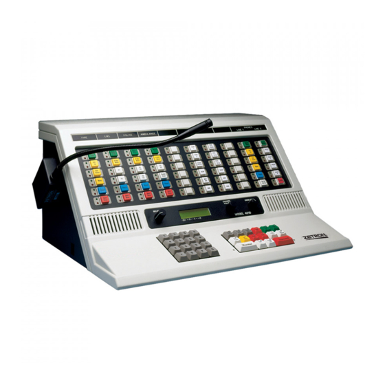
Radio dispatch console
Hide thumbs
Also See for 4010:
- Installation and programming (138 pages) ,
- Service manual (123 pages) ,
- Operation (38 pages)

Subscribe to Our Youtube Channel
Related Manuals for ZETRON 4010


Summary of Contents for ZETRON 4010
- Page 1 ZETRON Model 4010 Radio Dispatch Console Programming Manual Part No. 025-9229C.1 Please check for change information at the front of this manual. Copyright © 2008 by Zetron, Inc. All Rights Reserved...
- Page 3 Zetron’s warranty is published in the current United States Price List for Zetron Products. COPYRIGHT NOTICE The software in this product is copyrighted by and remains the property of Zetron, Inc. Reproduction, duplication, or disclosure is not permitted without prior written consent of Zetron, Inc.
-
Page 5: Table Of Contents
Table of Contents CHANGE INFORMATION WARRANTY INFORMATION 1. INTRODUCTION HARDWARE REQUIREMENTS................1-1 DEFINITIONS......................1-1 MANUALS......................... 1-1 2. INSTALLATION TO USE CPS, START HERE ..................2-1 Making a Working Program Diskette (floppy diskette system) ..... 2-1 Making a Working Directory (fixed disk system) .......... 2-2 3. - Page 6 MOTOROLA AND G.E. CODE PLANS ..............E-2 GENERAL ENCODING PLANS ................E-3 REACH ENCODING PLAN..................E-4 ZETRON TONE GROUPS FOR REACH ENCODING ........... E-4 REACH CODE PLAN....................E-5 FIVE/SIX-TONE FREQUENCIES AND TIMINGS..........E-5 DTMF TONE PAIR FREQUENCIES AND TIMING ..........E-6 QUICK CALL ONE (TWO-PLUS-TWO) FREQUENCIES AND TIMING....
- Page 7 1. INTRODUCTION HARDWARE REQUIREMENTS...............1-1 DEFINITIONS.....................1-1 MANUALS......................1-2...
-
Page 9: Introduction
Help is available through the use of pop-up help windows. In this manual both the Model 4010 and 4010R are referred to as the Model 4010 unless specifically stated otherwise. HARDWARE REQUIREMENTS To program the Model 4010 using CPS, you will need the following: •... -
Page 10: Definitions
There are several manuals which describe the operation, installation, service and programming of the Model 4010 Radio Dispatch Console. This manual describes how to use CPS to program the console keys. Table 1-1 lists the Model 4010 manuals and a description of their contents. - Page 11 2. INSTALLATION TO USE CPS, START HERE ................2-1 Making a Working Program Diskette (floppy diskette system) ....2-1 Making a Working Directory (fixed disk system) ........2-2...
-
Page 13: Installation
Making a Working Directory (fixed disk system). Due to copyright laws, the program diskette from Zetron does not contain a DOS (disk operating system) and therefore is not bootable. You will need a single blank diskette to format as described below. -
Page 14: Making A Working Directory (Fixed Disk System)
When the files are copied, remove the CPS master diskette from drive A: and store it in a cool, dry, safe place. Hopefully, you will never need it again. Label the new diskette “Zetron Model 4010 CPS” You have now created a working program diskette. Whenever you want to run the Model 4010 CPS program, type the following: A: <ENTER>... - Page 15 When the files are copied, remove the CPS master diskette from drive A: and store it in a cool, dry, safe place. Hopefully, you will never need it again. You have just created your CPS working directory. Whenever you want to run the Model 4010 CPS program, type the following: CD \CPS <ENTER> 4010 <ENTER>...
- Page 16 Section 2. Installation 025-9229C.1...
- Page 17 3. TUTORIAL INTRODUCTION ....................3-1 RUNNING CPS ....................3-1 CPS MENU AND DATA EDITING KEYS ............3-1 Using Menus ....................3-1 Getting Help.....................3-2 The ESC Key ...................3-2 Data Editing Keys ..................3-2 CREATING YOUR FIRST CONSOLE CONFIGURATION......3-3 Creating a New Channel ................3-4 Defining Console Keys ................3-7 Moving Console Keys................3-11 Copying Console Keys ................3-11 Listing Key Definitions to Printer............3-12...
-
Page 19: Tutorial
3. TUTORIAL INTRODUCTION This section presents the essential steps needed to run CPS to program a Model 4010. Information about starting the program and navigating through the menus is followed by a step-by-step tutorial that will quickly show you how to create a new channel, define, move and copy console keys, and print reports. -
Page 20: Getting Help
Section 3. Tutorial Getting Help At certain points in the program, you may pop-up a help window by pressing the ? (question mark) key. The help window provides information about the input field where help was requested. After reading the help window, press the key to remove the window from the screen and return to the field or menu you were working on. -
Page 21: Creating Your First Console Configuration
System configuration Selection [P] Figure 3-2. EDIT Menu To communicate with external devices (base stations, transmitters, etc.), the Model 4010 system needs to know what kind of channels are connected to it. To define these channels, press the key from the EDIT menu. This selection will cause the SYSTEM... -
Page 22: Creating A New Channel
Section 3. Tutorial ZETRON MODEL 4010 CONSOLE PROGRAMMING SYSTEM Select [E] Read Write drIve Edit List Upload Program Quit ?Help Position configuration SYSTEM CONFIGURATION System configuration A. Channel Configuration B. Channel Monitor Configuration Selection [P] C. Channel Paging Configuration D. Paging Format Configuration E. - Page 23 “Yes” to create a new channel. Next the program will place the cursor in the Channel Name field. Enter a channel name and press ENTER ZETRON MODEL 4010 CONSOLE PROGRAMMING SYSTEM Select [E] Read Write...
- Page 24 Section 3. Tutorial Press ENTER to accept standard protocol. Next the TONE STANDARDS menu, F igure 3-7 is displayed. ZETRON MODEL 4010 CONSOLE PROGRAMMING SYSTEM Select [E] Read Write drIve Edit List Upload Program Quit ?Help Position configuration Channel Number: 1...
-
Page 25: Defining Console Keys
Press the key or position the menu bar over “Key Definition” and press ENTER The next menu displayed will allow you to select which Model 4010 panel you wish to define keys for, as shown in F igure 3-10 ZETRON MODEL 4010 CONSOLE PROGRAMMING SYSTEM... - Page 26 The first window is a representation of the Model 4010 channel control panel. Notice that the key in the upper left hand corner of the panel is highlighted and pressing the arrow keys will move the highlighted key around the panel.
- Page 27 Section 3. Tutorial Define Erase Move Copy Spare Figure 3-12. KEY EDITING Menu Notice that by pressing the LEFT RIGHT ARROW keys, the highlighted menu option can be changed. Position the menu bar over the “Define” option and press ENTER The KEY FUNCTIONS menu, F igure 3-13 , will be displayed.
- Page 28 Type of Channel: Tone Control D. Instant Select E. Miscellaneous Selection [U] E. Instant Select with Voting Standard T2R2/T22R with PL ZETRON MODEL 4010 UPPER PANEL Selection [A] F. Instant Transmit G. Volume Keys Emergency ANI ACK: disabled H. Patch I. Main / Standby J.
-
Page 29: Moving Console Keys
Section 3. Tutorial Several windows will now be removed from the screen and you can now select another key to define. Program the key directly under the frequency select F2 key to be a frequency select F1 key for channel 1. Moving Console Keys Using the move key function, you can now correct the transposition of the frequency select keys. -
Page 30: Listing Key Definitions To Printer
Section 3. Tutorial for channel 1 and substitute channel 2 for channel 1 or you can use the copy function. The copy function makes it easy to replicate groups of keys on the console. Start by moving the highlighted key to the upper left hand corner of the panel. Next press and then select the Copy function. -
Page 31: Quitting Cps
Section 3. Tutorial ZETRON MODEL 4010 CONSOLE PROGRAMMING SYSTEM Select [L] Read Write drIve Edit List Upload Program Quit ?Help Key Configuration System configuration Selection [K] Figure 3-16. LIST Menu The report will begin printing on the printer. At any time during the printing of the report, pressing the key will cancel the printing of the report. - Page 32 Section 3. Tutorial ZETRON MODEL 4010 CONSOLE PROGRAMMING SYSTEM Select [Q] Read Write drIve Edit List Upload Program Quit ?Help < NAME > Select file name to save configuration file Default name is listed first. Figure 3-18. Save Configuration File Windows Notice the current system name is the first file listed.
-
Page 33: Tutorial Conclusion
Section 3. Tutorial TUTORIAL CONCLUSION This tutorial described how to create a new channel, define, move and copy console keys, and print reports. For a complete description of CPS functions, see Section 4. The complete CPS menu structure is presented in Appendix D. 025-9229C.1 3-15... - Page 34 Section 3. Tutorial 3-16 025-9229C.1...
- Page 35 G. Transmit Timeout..............4-17 H. Priority Marker Frequency............4-18 I. Priority Marker Duration ............4-18 J. Priority Marker Interval............4-18 K. Priority Marker Amplitude............4-18 PRINTING KEY AND SYSTEM CONFIGURATIONS ........4-18 PROGRAMMING A MODEL 4010 ..............4-18 UPLOADING A SYSTEM CONFIGURATION TO A PC........4-20 QUITTING CPS ....................4-20...
-
Page 37: Program Operation
A system configuration contains all of the key definitions for the two programmable Model 4010 panels and all channels. After editing the configuration, it is written back to the disk using the Write function. -
Page 38: Writing A System Configuration File
Section 4. Program Operation WRITING A SYSTEM CONFIGURATION FILE The Write function updates the configuration file stored on the disk by writing the current edit buffer to disk. The Write function can be activated in three ways. First, by pressing from the MAIN menu. -
Page 39: Creating A New System Configuration
EDITING THE CURRENT SYSTEM CONFIGURATION FILE Most CPS work is done with the Edit function. The Edit function is divided into two main areas. The first area deals with programming the Model 4010 panels. The second area deals with system configuration. -
Page 40: Key Definition
If spare inputs have been enabled, this menu will also include a Spare Inputs selection. Spare inputs are conceptually the same as pressing a key on a panel. The Model 4010 has eight spare inputs. The inputs are located on pins 1 through 8 on connector P8. To activate an input, short a spare input pin to ground through a contact closure. - Page 41 Section 4. Program Operation Next, the KEY MODIFICATION menu is displayed, as shown in Figure 4-5. From this menu, you may define, erase, move, or copy a key or you may assign an existing key to a spare input (if enabled). Define Erase Move Copy...
- Page 42 Section 4. Program Operation Frequency Select Key, the program will display the send function window. If “Upon Transmit Only” is selected, the function will be sent whenever the channel is transmitted on. Selecting “Instantly” will cause the function to be sent when the key is pressed.
- Page 43 Section 4. Program Operation Table 4-2. Key Categories — Custom Channel Functions Motorola/GE Custom Tone Functions Custom DC Functions Control Currents* No Tone No Current No Current 650 Hz + 2.5 mA + 2.5 mA 750 Hz + 5.0 mA + 5.5 mA 850 Hz + 7.5 mA...
- Page 44 Auxiliary Input Port numbers 9-38 are assigned to the optional Expanded Aux. I/O Card(s) (Part No. 702-9448) as follows: 9-14 to the first Aux. I/O Card, 15-20 to the second Aux. I/O Card, etc. This allows the Model 4010 to support up to five Aux. I/O Cards (30 ports).
- Page 45 Section 4. Program Operation If present, selecting one of the three Spare Output menu options displays the SPARE OUTPUT menu. Select a previously defined output port by entering a number from 1 to 8 and pressing . One of the main uses of the Spare Outputs is controlling ENTER telephone equipment connected to the console.
-
Page 46: Position Layout
Section 4. Program Operation B. Position Layout This selection allows expansion panels to be incorporated into the Model 4010 configuration. Figure 4-7 is displayed if this selection is pressed. Panel #2 or #3 are the only options that are available. Once either 2 or 3 is entered Figure 4-x2 is diplayed. Panel 2 must be entered before Panel 3, or an error message is displayed. -
Page 47: Ani Decode / Display
Section 4. Program Operation level for all channels of the system. The percentage entered will be rounded up to the nearest integer multiple of 12.5. Default Volume Level Select option from the AUDIO CONTROLS menu. Enter a number from 0 to 99 representing the percentage of total volume to be used as a “power up”, or default, volume level for all channels of the system. - Page 48 Section 4. Program Operation Select for edit from the MAIN menu and then select to display the next menu. Next, select for ANI Decode / Display and the ANI menu will be displayed. The two ANI menu selections are described below: 1.
-
Page 49: Display Operation
To set the position’s ANI address, select Destination from the ANI menu. The Model 4010 has two ANI addresses: a primary and a secondary. Normally the primary address is used to select a group of consoles, while the secondary address is used to select an individual console within the group. - Page 50 Deskmic from the next menu. Press the key to return to the MAIN EDIT menu. Table 4-3. Model 4010 Audio Sources and Steering Notes There are only four external audio sources: 1. “D” Mic - Desktop mic 2. “E” Mic - Headset or handset 3.
-
Page 51: System Configuration
Section 4. Program Operation MIC SW PTT Input Audio Source Spare 9 Audio Source Aux. PTT — — — Aux. Audio D PTT — — — Desk Mic E PTT/Soft Tx Always E — — “E” Mic E PTT/Soft Tx Always D —... -
Page 52: Channel Monitor Configuration
Auxiliary Input Port numbers 9-38 are assigned to the optional Expanded Aux. I/O Card(s) (Part No. 702-9448) as follows: 9-14 to the first Aux. I/O Card, 15-20 to the second Aux. I/O Card, etc. This allows the Model 4010 to support up to five Aux. I/O cards (30 ports). 4-16... -
Page 53: Transmit Timeout
Section 4. Program Operation Auxiliary Input Port numbers 1-8 are assigned to the Model 4010 main PC board Spare/Aux. inputs (on connector P8) if these inputs have been configured as auxiliary inputs. If the inputs have been defined as spare inputs instead (the default), Auxiliary Input Port numbers 1-8 are unavailable and cannot be selected in the following menus Auxiliary Output Port numbers 9-38 are assigned to the optional Expanded Aux. -
Page 54: Printing Key And System Configurations
Connect one end of the supplied serial cable to the COMB phone jack on the right side of the Model 4010 console. Connect the other end of the cable to serial port COM1 or COM2 on the computer. See Figure 4-13. - Page 55 When the cable is connected between the computer and the console, locate a small slide switch on the bottom of the console. Lift the front of the Model 4010 and find the switch at the center of the bottom panel. Slide the switch to the left.
-
Page 56: Uploading A System Configuration To A Pc
Section 4. Program Operation UPLOADING A SYSTEM CONFIGURATION TO A PC The Upload function transfers a previously downloaded system configuration back up to the computer. The configuration can then be modified, saved to disk, and/or used to program another console. The only information not retained are the optional channel and auxiliary I/O names because these are not part of the data when downloading to the console. -
Page 57: Appendix A. Tone-Remote Function Definition
APPENDIX A. TONE-REMOTE FUNCTION DEFINITION Tone Freq. T1R1 T2R2 T4R4 T8R8 650Hz — — — — 750Hz — — — — 850Hz — — — 950Hz — — — 1050Hz PL4/WC 2 OFF PL4/WC 2 OFF WC 2 OFF 1150Hz PL3/WC 2 ON PL3/WC 2 ON WC 2 ON... -
Page 59: Appendix B. Dc-Remote Function Definition
APPENDIX B. DC-REMOTE FUNCTION DEFINITION Current T1R1 STD T1R1 PAGING T2R2 T4R4 0.0 mA + 2.5 mA — — — — + 5.0 mA — + 7.5 mA — — — — +10.0 mA — — — — +12.5 mA RPTR ON F1 W PL +15.0 mA... -
Page 61: Appendix C. Generating Motorola/Ge Control Currents
APPENDIX C. GENERATING MOTOROLA/GE CONTROL CURRENTS Standard Motorola and GE DC Remote Control currents may be generated with Model 4010 DC Channel cards. Normally, the available positive and negative currents, which are based on 2.5 mA increments, will achieve proper control of DC Remote Controlled base stations. However, a feature on the DC Channel card allows alternate Motorola and GE currents to be achieved. - Page 63 APPENDIX D. CPS MENU STRUCTURE PURPOSE ......................D-1 Top Menu....................D-1 EDIT ........................D-2 Position Configuration ................D-2 A. Key definition .................D-2 B. Position Layout ...............D-25 C. Audio Controls ................D-25 D. ANI Decode/Display...............D-27 E. Display Operation..............D-29 F. Miscellaneous ................D-30 System Configuration ................D-31 A. Channel Configuration............D-32 B.
-
Page 65: Appendix D. Cps Menu Structure
Zetron Series 4010 dispatch console using CPS (Console Programming System). CPS creates or modifies a configuration file for the Series 4010 dispatch consoles. Each menu you encounter while programming the console is explained along with a brief description of the effects. -
Page 66: Edit
System configuration Selection [P] Figure D-2. EDIT Menu Position Configuration This menu (see Figure D-3) allows you to assign Model 4010 key functions and define certain system options. Use the DOWN ARROW keys or type the letter in the first column to select the desired menu item. - Page 67 Appendix D. CPS Menu Structure ZETRON MODEL 4010 CONSOLE PROGRAMMING SYSTEM Select [E] Read Write drIve Edit List Upload Program Quit ?Help Position configuration A. Key Definition Upper Panel System configuration B. Audio Control Lower Panel C. ANI Decode / Display...
- Page 68 Type of Channel: Tone Control D. Instant Select E. Miscellaneous Selection [U] E. Instant Select with Voting Standard T2R2/T22R with PL ZETRON MODEL 4010 UPPER PANEL Selection [A] F. Instant Transmit G. Volume Keys Emergency ANI ACK: disabled H. Patch I. Main / Standby J.
- Page 69 Appendix D. CPS Menu Structure current” will cause the previous control current for that function to be maintained; that is no current change. Table D-1. Receive Function DC Controlled Channel Tone Controlled Channel Receive Function Receive Function A. No current A.
- Page 70 Appendix D. CPS Menu Structure Table D-2. Transmit Function DC Controlled Channel Tone Controlled Channel Transmit Function Transmit Function A. No current A. No Tone B. + 2.5 ma B. 650 HZ C. + 5.0 ma C. 750 HZ D. + 7.5 ma D.
- Page 71 Appendix D. CPS Menu Structure NSTANT ELECT Instant Select differs from the normal Select function in that after the Select is performed, a DC or Tone control function is sent. This is normally used on a multi- frequency base station to select a channel at a desired frequency. Several Instant Select keys may be assigned to a single channel even though only one can be active at a time.
- Page 72 Appendix D. CPS Menu Structure OLUME DJUST KNOB The volume adjust key allows the volume of a specific channel to be set or changed at the console. Pressing the key will cause the current volume level (in percentage) to be displayed.
- Page 73 Appendix D. CPS Menu Structure ANI S OURCE This function is assigned to the switch’s lights only. The ANI option must be installed for this function to have meaning. Whenever a valid ANI is displayed, the ANI source light for the channel that received the ANI will illuminate. This light will be illuminated (flashing) until the ANI review key is activated.
- Page 74 Appendix D. CPS Menu Structure SYSTEM FUNCTIONS A. Transmit Keys B. Monitor C. Site Intercom D. Alert E. Mute Keys F. Simultaneous Select G. Group Keys H. Priority Marker I. Speaker / Headset J. Diagnostics Reset K. Clock Set L. ANI Keys M.
- Page 75 Appendix D. CPS Menu Structure RANSMIT ANY CHANNEL This key will cause the last channel that had received audio (“Call” activity) to transmit. The channel will not be selected. RANSMIT SELECTED CHANNELS This key will cause the last “Selected” channel that had received audio (“Call” activity) to transmit.
- Page 76 Appendix D. CPS Menu Structure IREN This key causes a slow siren-like sound to be transmitted on the “selected” channel. IREN This key causes a fast siren-like sound to be transmitted on the “selected” channel. ARBLE This key causes a warble-like sound to be transmitted on the “selected” channel. 25 F ODEL ARBLE...
- Page 77 Appendix D. CPS Menu Structure IMULTANEOUS ELECT Holding this key and pressing channel “Select” keys will cause multiple channels to be “Selected”. All the channels thus selected will transmit when the transmit key is pressed and all their received audio will be routed to the “Select” speaker. This same procedure can be used to deselect currently selected channels, i.e.;...
- Page 78 Appendix D. CPS Menu Structure GROUP SELECT CH 1 [ ] CH 2 [ ] CH 3 [ ] CH 4 [ ] CH 5 [ ] CH 6 [ ] CH 7 [ ] CH 8 [ ] Enter ‘E’ to select a channel, a space to disable a channel.
- Page 79 Appendix D. CPS Menu Structure PRIORITY MARKER Enter Channel Number from 1 to 14 ‘T’ for Transfer ‘S’ for selected channel Selection [__] Figure D-18. PRIORITY MARKER Menu PEAKER EADSET This key will cause the speaker audio to be toggled between the speakers and headset. The green LED will indicate that the audio is routed to the speaker;...
- Page 80 Appendix D. CPS Menu Structure A. ANI Review B. ANI Select Select ANI Key Type [B] Figure D-19. ANI KEYS Menu ANI R EVIEW Because ANIs are received from various radios, they will be decoded and stored in a “stack” in memory. The ANIs are reviewed and removed from the stack by repeatedly pressing this key.
- Page 81 Select one of the paging functions shown in Figure D-21 to assign to the key. Note that the “Instant Call” and “Page Safety” functions represent optional features. They can always be programmed, but will generate an error message in the Model 4010 console if the Instant Call Paging option has not been installed.
- Page 82 If a page transmission is in progress, it will also immediately abort the page transmission. This function should always be programmed if the Model 4010 console is to be used for paging. D-18...
- Page 83 Appendix D. CPS Menu Structure This paging function will terminate any manual page entry in progress (as if a PAGE ENTER key had been pressed), and begin transmitting the manual page stack on the currently selected channel(s) in the order the pages were stacked (entered). The page stack is retained and can be transmitted again (on different channel(s), for example) by pressing this key again.
- Page 84 Appendix D. CPS Menu Structure I ON/OFF Toggle the Wild Card I function on the appropriate tone controlled radio channel. Refer to Appendix A or B for the function actually transmitted. II ON/OFF Toggle the Wild Card II function on the appropriate tone controlled radio channel. Refer to Appendix A or B for the function actually transmitted.
- Page 85 Appendix D. CPS Menu Structure A. Output RED active, OFF inactive B. Output RED active, GREEN inactive C. Input/Output RED output, GREEN input D. Input GREEN active, OFF inactive E. Input RED active, GREEN inactive F. Dual Input ON active, OFF inactive G.
- Page 86 PARE UTPUT ATCHING The eight spare outputs are located on connector 7 on the Model 4010 main PC board. Note: If Spare Outputs 7 and 8 are not programmed, they will function as follows: Spare Output 7: Will be ON whenever an ANI is displayed on the console.
- Page 87 Appendix D. CPS Menu Structure The assigned spare output will toggle on and off with each press of the spare output latching key. The red LED will toggle to show the state of the output. PARE UTPUT OGGLE The assigned spare output will toggle on and off with each press of this key. The red and green LEDs will toggle to show the state of the output.
- Page 88 Appendix D. CPS Menu Structure If the channel has been defined as a tone controlled channel, you will be asked to select the desired transmit and receive tone from the values shown in Table D-1 and Table D-2. The receive tone selected will be sent whenever the key is pressed. The transmit function will be sent on transmit.
-
Page 89: Position Layout
Appendix D. CPS Menu Structure this key. The spare input and associated key are effectively in parallel such that activating either one will execute the function. SPARE INPUTS Spare input 1 Spare input 2 Spare input 3 Spare input 4 Spare input 5 Spare input 6 Spare input 7... - Page 90 (inaudible) or set to any desired level up to 99% of full. Any number from 0 to 99 can be entered, but because the Model 4010 channel card has only eight discrete volume levels, the percentage entered will be rounded up to the nearest integer multiple of 12.5.
-
Page 91: Ani Decode/Display
Appendix D. CPS Menu Structure a) Don’t Mute Idle Channels This selection does not mute any idle channels. b) Mute All Idle Channels This selection causes all channels that have no received audio (Call activity) to be electronically muted or turned off. This is used when a system contains a large number of channels to prevent inherent channel noise from summing together and causing an annoying “hiss”... - Page 92 Appendix D. CPS Menu Structure A. No ANI display B. ANI display enabled C. ANI Channel Unmute operation D. Emergency ANI Acknowledge ANI Operation [C] Figure D-42. ANI OPERATING MODE Menu a) No ANI Display Choosing this function will disable the ANI capability. Even though ANIs will be received and decoded, none will be displayed.
-
Page 93: Display Operation
Appendix D. CPS Menu Structure 2) Destination Two addresses may be decoded by the consoles. Normally the primary address is decoded by all positions. Each position can then have its own unique secondary address allowing a mobile to call a particular operator or console. In the window shown in Figure D-46, select the 1- to 6-digit address for primary and secondary. -
Page 94: Miscellaneous
Appendix D. CPS Menu Structure F. Miscellaneous Miscellaneous panel configuration functions are shown in Figure D-48. A. Audio Source for ‘Soft’ Xmit Keys B. Instant Select Key Display Mode C. Received ‘Call’ light duration D. Dynamic Mic selection E. Parallel Remote Status enabled Selection [ ] Figure D-48. -
Page 95: System Configuration
(see Figure D-51). Prior to configuring the system, it is imperative that the programmer has a complete understanding of the radio system that is to be controlled by the Model 4010 console. 025-9229C.1 D-31... -
Page 96: Channel Configuration
Appendix D. CPS Menu Structure ZETRON MODEL 4010 CONSOLE PROGRAMMING SYSTEM Select [E] Read Write drIve Edit List Upload Program Quit ?Help Position configuration SYSTEM CONFIGURATION System configuration A. Channel Configuration B. Channel Monitor Configuration Selection [P] C. Channel Paging Configuration D. - Page 97 Appendix D. CPS Menu Structure 1) DC Control-Momentary Use this DC control option if the radio requires only a momentary DC current to perform the desired function. 2) DC Control-Constant Some radios require that the control current be maintained constantly in order to perform the desired function.
- Page 98 Appendix D. CPS Menu Structure T4R4 Standard DC controlled radio with four frequency transmit and receive capability. Choosing this option allows frequency select keys to be programmed. 3) Tone Control Two types of tone control protocol are available: Standard or Custom (see Figure D-54). Consult the radio specifications prior to selecting a channel type.
-
Page 99: Channel Monitor Configuration
The default control functions are 2050 Hz for tone remotes and -2.5 mA for DC remotes. C. Channel Paging Configuration The Model 4010 Console allows certain paging parameters to be defined (see Figure D-57) on a per-channel basis. These parameters are in effect only when a page is being transmitted on the channel. - Page 100 Appendix D. CPS Menu Structure PAGING FUNCTION Paging channel number [3 ] A. No Tone 650 HZ Keyup delay (0.0-10.0) [0.60] 750 HZ 850 HZ 950 HZ De-emphasis enabled ? [N] F. 1050 HZ G. 1150 HZ H. 1250 HZ Inter-stack delay (0.0-10.0) [0.20] I.
-
Page 101: Paging Format Configuration
(or allowed) since the Model 4010 already knows what type of page it will be. Note that when programming Instant Call Key paging stack(s), a leading digit is always required. - Page 102 To then transmit the stacked page(s) on the selected channel(s), press the “PAGE SEND” key. Alert tones 1 through 4 are predefined in the Model 4010 console. The Beep Alert and Delay function are defined by you via the windows shown in Figure D-60.
-
Page 103: Edit Custom Calls
The Delay function is used to create a delay within a paging stack during which time the Model 4010 console stops all transmission, opens the channel PTT relay, and is in the receive mode for the number of seconds specified in the fourth window shown in Figure D-60. After this time, the normal transmit mode is resumed and paging continues with the next page in the stack. -
Page 104: Input/Output Configuration
This function is used to create and name auxiliary inputs and outputs used in the console, and to set the mode of the Spare/Aux. Ports on the Model 4010 main PC board (see Figure D-62). Port numbers 1-8 are assigned to standard main PC board Spare/Aux. Ports. Port numbers 9- 38 are assigned to any optional Expanded Aux. -
Page 105: Other Menus
The default duration is 120 mS. You may enter any other value from 10 mS to 630 mS in 10 mS increments. This custom duration can be enabled on a per-tone-channel basis by the option bit switch on the back of the card, as described in Model 4010 Radio Dispatch Console Installation Manual (Part No. 025-9227). - Page 106 Section 4. QUIT After all programming is completed, you may exit the Model 4010 CPS by selecting this function. If your changes have not been saved to disk, you will be asked if you wish to save them before leaving CPS. You may decide to discard all changes and exit without saving in which case any changes to the existing configuration file will be lost.
- Page 107 Appendix D. CPS Menu Structure If you elect to save your changes, you will be prompted for the file in which you wish to store them. The highlighted file name in the displayed menu will be the configuration file that was originally loaded. To save the new configuration to this file, just press ENTER.
- Page 108 Appendix D. CPS Menu Structure D-44 025-9229C.1...
- Page 109 MOTOROLA AND G.E. TONE GROUP FREQUENCIES.......E-1 MOTOROLA AND G.E. CODE PLANS ............E-2 GENERAL ENCODING PLANS ...............E-3 REACH ENCODING PLAN................E-4 ZETRON TONE GROUPS FOR REACH ENCODING ........E-4 REACH CODE PLAN..................E-5 FIVE/SIX-TONE FREQUENCIES AND TIMINGS..........E-5 DTMF TONE PAIR FREQUENCIES AND TIMING ........E-6...
-
Page 111: Appendix E. Paging Format Reference Tables
APPENDIX E. PAGING FORMAT REFERENCE TABLES MOTOROLA AND G.E. TONE GROUP FREQUENCIES Tone Groups Tone Mot 1 Mot 2 Mot 3 Mot 4 Mot 5 Mot 6 Mot A 330.5 569.1 1092.4 321.7 553.9 1122.5 358.9 349.0 600.9 288.5 339.6 584.8 1153.4 398.1... -
Page 112: Motorola And G.e. Code Plans
Appendix E. Paging Format Reference Tables MOTOROLA AND G.E. CODE PLANS Code Plans Pager Cap- Mot B Mot C Mot D Mot E Mot F Mot G Mot H Mot J Mot K code Groups Groups Groups Groups Groups Groups Groups Groups Groups... -
Page 113: General Encoding Plans
Appendix E. Paging Format Reference Tables GENERAL ENCODING PLANS General Plan Modified Gen. Plan General Alternate Plan Pager Cap- Tone Diagonal Tone Diagonal Pager Tone code Groups Tone Groups Tone Capcode † Groups 569.1 569.1 953.7 + Mot 1 979.9 979.9 953.7 + Mot 2 569.1... -
Page 114: Reach Encoding Plan
2612.0 1553.0 923.0 549.0 2523.0 1500.0 892.0 530.0 2437.0 1449.0 862.0 512.0 495.0 Notes: Frequencies are shown in hertz. ZETRON TONE GROUPS FOR REACH ENCODING Tone Groups Tone 1980.0 1177.0 1400.0 832.0 588.0 2704.0 1608.0 1912.0 1137.0 804.0 2612.0 1553.0 1847.0... -
Page 115: Reach Code Plan
Appendix E. Paging Format Reference Tables REACH CODE PLAN Individual Call Pager Tone Groups Capcode (x+y) Z5+Z3 Note that the ones/tens digit encoding, shown by ‘x’ and ‘y,’ reverses position for each 100 pager Z1+Z2 block. In Motorola/GE plans, the first tone is Z2+Z1 always the tens digit and the second tone is the ones digit. -
Page 116: Dtmf Tone Pair Frequencies And Timing
Appendix E. Paging Format Reference Tables DTMF TONE PAIR FREQUENCIES AND TIMING Column 1 Column 2 Column 3 Column 4 First 697/1209 697/1336 697/1477 697/1633 Second 770/1209 770/1336 770/1477 770/1633 Third 852/1209 852/1336 852/1477 852/1633 ∗ Fourth 941/1336 941/1477 941/1633 941/1209 Notes: Frequencies are shown in hertz. -
Page 117: Model 4010 Cps Menu Structure
Model 4010 Programming Manual MODEL 4010 CPS MENU STRUCTURE READ LIST UPLOAD WRITE DRIVE EDIT PROGRAM QUIT HELP Key Configuration Position Configuration NOTE System Configuration System Configuration The codes at the end of the menu names refer to the items in the Appendix D Table of Contents and Edit subsection;...
Need help?
Do you have a question about the 4010 and is the answer not in the manual?
Questions and answers