Table of Contents
Advertisement
Quick Links
Advertisement
Table of Contents

Subscribe to Our Youtube Channel
Related Manuals for Zubler V6000


Summary of Contents for Zubler V6000
- Page 1 V6000 Individual Vacuuming Unit Operating instruction 11-2012 www.zubler.de...
-
Page 2: Table Of Contents
Content Introduction Page 0.1 Declaration of conformity 0.2 General hints 0.3 Regular usage 0.4 Environment 0.5 Setting up 0.5.1 Conn. the unit 0.5.2 Conn. the working tool 0.5.3 Remote switching Functions Page 1.1 Front panel 1.2 Starting the unit 1.3 Operation Adjustments Page 2.1 Sensitivity settings... -
Page 3: Declaration Of Conformity
Introduction Declaration of conformity Zubler GmbH Buchbrunnenweg 26 89081 Ulm-Jungingen /Germany declare, that the product vacuuming unit V6000 corresponds to the regulations of the following directives in regard to protective requirements 2004/108/EG EMV-Directive 2006/95/EG Low-Voltage Directive 2006/42/EG Machines Directive Any modification not specifically approved by us voids the validity of this declaration. -
Page 4: General Hints
General hints Dear customer, we are pleased that you have made the decision to purchase a zubler pro- duct and wish you a comfortable working with our equipment. We are asking you to read the instructions carefully before putting the installation into operation. -
Page 5: Setting Up
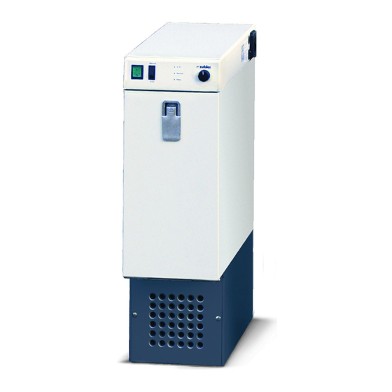
3 Front door 0.5.1 Connecting the unit Before connecting the to the ■ V6000 mains power, check if the voltage given on the number plate corre- sponds with the specifications of your local mains power supply. Fig. 0.2: side view Plug the enclosed power cord into the ■... -
Page 6: Remote Switching
Plug in the power cord of the working ■ ZUBLER Gerätebau GmbH tool (e.g. handpiece) into the autom. Buchbrunnenweg 26 power socket(7). D-89081 Ulm Tel. +49(0)731 1452-0 / www.zubler.de The power consumption of the wor- ■ Absauganlage king tool may not exceed 450W ! V6000 Spannung 230V Gesamtleistung max. -
Page 7: Functions
Functions Front panel Manual ® O. K. Service Filter Auto Fig. 1.1: Front panel Starting the unit 9 LED Service Switch the Automatic / Manual switch ■ 10 LED OK (11) to Manual position to use the 11 Autom. / Manual switch manual operation mode. -
Page 8: Operation
Operation The green LED “OK” (10) indicates a ■ normal operation. The red LED “Service” (9) indicates ■ an electric malfunctioning (e.g. worn out carbon brushes of the motor). The red LED “Filter” (12) indicates a ■ filled up filterbag, a clogged finefilter cartridge or a clogged intake line. -
Page 9: Adjustments
Adjustments Sensitivity settings Plug in the power cord of the technical gear (e.g. handpiece) into the automatic socket (27) (Fig.0.2) of the suction unit. The max. load may not exceed 450W ! Use one of the three predefined sensitivity settings of the external sensitivity switch (25). -
Page 10: Kavo K-Control
■ The adjustment is performed by turning rheostat B on the PC-board into the needed direction. If the suction unit does not shut OFF ■ although the handpiece is not actuated, the sensitivity is too high. Turn rheostat B to minus (- = CCW). If in a reversed case the suction unit ■... -
Page 11: Filterchange
Filterchange Replacing the filterbag Switch off the unit with the main ■ switch (14) and open the door lock (1). ■ Open the front door (3) and pull out the filter cage (16). Fig. 3.1 16 Filter cage Perform a filter change only with an 17 Filter bag appropriate protective equipment. - Page 12 ■ Open the cage door by unlocking the 2 fasteners. Pull the gasket off the nozzle and take ■ out the filter bag (17). Close the opening with the adhesive foil. ■ Store the filter bag immediately in a ■ dust-tight plastic bag and dispose the filter bag according to your local guidelines.
-
Page 13: Replacing The Finefilter
Replacing the finefilter V6000 is additionally equipped with a finefilter cartridge. Its function is to collect fine dusts, which volatilizes through the filter bag or are set free during the replacement. If the red LED “Filter” (12) (Fig.1.1) is still... -
Page 14: Intake System
4. Intake system Requirements Basic requirements upon an intake sytem are beside an optimal dirt collection the avoidance of disturbing flow noises and the encouragement of an ergonomic working position. R1200/R1250 These properties can only be granted with an intake system especially matching the vacuuming unit consisting of Suction funnel R1200 ■... -
Page 15: Maintenance
Maintenance Before cleaning and servicing the gear and also before replacing spare parts the suction unit must be separated from the mains supply ! Wipe off any outer soiling with a mere moist cloth, protect the suction unit from water penetration ! Maintenance works on electrical parts of the unit must solely be carried out by expert personnel or by persons having been trained. -
Page 16: Troubleshooting
Troubleshooting Fehlererkennung Ursache Abhilfe Change the main LED „Filter“ illumi- Due to a filled up filter (see chapter nated filter bag and/or a "Main filter clogged fine filter change"). If the as well as a clog- indication does not ged suction line, extinguish also the minimum suc- change the fine fil-... - Page 17 Fehlererkennung Ursache Abhilfe Check the mains Suction does not No mains supply connection. Switch start (main switch or mains switch the main switch (14) is NOT illumina- not switched on. (14) into "On" posi- ted) Fuse burnt-out tion, the main due to overchar- switch is illumina- ging.
-
Page 18: Data
Data Spare parts: Pos. Name Order No. Pos. Name Order No. 1.0 Filter housing 570/2202 1.4.3 Filter bag, feeded 556/035 1.0.1 Autom. power socket 012/005 1.5 Electronic housing 570/2375 Socket frame 012/0051 Front panel 020/006 1.0.2 Sensitivity switch 019/0011 1.5.1 Main switch I/O 019/0061 1.0.3 low-heat-device socket 012/0031... -
Page 19: Dimensions
Dimensions: Fig. 7.1 Technical data: Width 200 mm Height 680 mm Depth 610 mm Weight 31 kg Tension (see number plate) 100V / 115V 230V / 240V 50-60 Hz 50-60 Hz Fusing main fuse T10 A T6,3 A autom. socket (internal) T4 A T2 A Total power consumption... - Page 20 Bxxxxx / 11-2012 www.zubler.de Zubler Gerätebau GmbH Buchbrunnenweg 26 D-89081 Ulm-Jungingen...
Need help?
Do you have a question about the V6000 and is the answer not in the manual?
Questions and answers