
Related Manuals for Vertex 2158

Summary of Contents for Vertex 2158
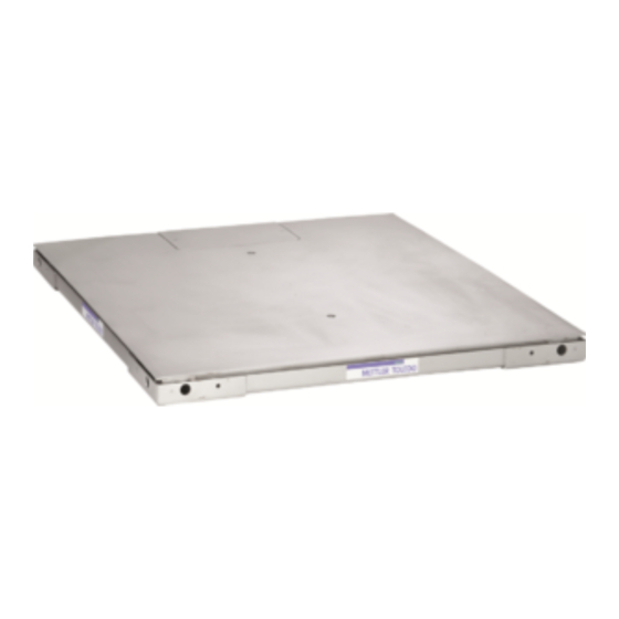
- Page 1 2158 Analog ® 2160 DigiTOL 2162 IDNet ® Vertex Floor Scales Service Manual A14691400A (11/96)
- Page 2 ©Mettler-Toledo, Inc. 1996 No part of this manual may be reproduced or transmitted in any form or by any means, electronic or mechanical, including photocopying and recording, for any purpose without the express written permission of Mettler-Toledo, Inc. U.S. Government Restricted Rights: This documentation is furnished with Restricted Rights.
- Page 3 Declaration of conformity Konformitätserklärung Déclaration de conformité Declaración de Conformidad Verklaring de overeenstemming Dichiarazione di conformitá We/Wir/Nous/WIJ/Noi: Mettler-Toledo, Inc. 1150 Dearborn Drive Worthington, Ohio 43085 declare under our sole responsibility that the product, erklären, in alleiniger Verantwortung, daß dieses Produkt, déclarons sous notre seule responsabilité...
- Page 4 METTLER TOLEDO Publication Problem Report If you find a problem with our documentation, please complete and fax this form to (614) 438-4783 Publication Name: Publication Part Number: Publication Date: PROBLEM(S) TYPE: DESCRIBE PROBLEM(S): INTERNAL USE ONLY o Technical Accuracy Text Illustration o Completeness Procedure/step...
- Page 5 3) Normal maintenance or consumable items. This warranty covers only the Models 2158, 2160, and 2162 VERTEX® floor scale understructure. Refer to Mettler Toledo Standard Product Warranty for coverage of other scale system components including scale instrument, printer, and/or other accessories.
- Page 6 INTRODUCTION This publication is provided as a guide for the trained technician for installing, calibrating, ® and servicing the 2158, 2160, and 2162 VERTEX . Repair or adjustment by unauthorized ® persons voids the METTLER TOLEDO warranty. Information regarding your nearest METTLER TOLEDO Distributor, Sales, and Service...
- Page 7 PRECAUTIONS WARNING ONLY PERMIT QUALIFIED PERSONNEL TO READ this manual SERVICE THIS EQUIPMENT. EXERCISE BEFORE installing, CARE WHEN MAKING CHECKS, TESTS AND operating, or servicing this ADJUSTMENTS THAT MUST BE MADE WITH equipment. POWER ON. FAILING TO OBSERVE THESE PRECAUTIONS CAN RESULT IN BODILY HARM.
-
Page 8: Table Of Contents
CONTENTS Chapter 1: Specifications ..................1-1 Power Supply Requirements ..................1-1 Accuracy........................1-1 Load Cells ......................... 1-2 End Loading....................... 1-3 Platform Assembly ..................... 1-3 Support Frames......................1-4 Chapter 2: Inspection and Site Selection .............2-1 Inspection........................2-1 Site Selection ......................2-1 Chapter 3: Installation (Top-of-Floor) Locate ........................ - Page 9 General........................10-1 Isolate the Problem ....................10-2 Check Wiring......................10-2 Check Load Cells......................10-3 Check Mechanical Components .................10-4 Load Cell Replacement Procedure ................10-4 Chapter 11: Service Parts................. 11-1 Chapter 12: Reference Material ................ 12-1 Reference Drawings....................12-1 Recommended Spare Parts ..................12-1 Load Cell Data......................12-1...
-
Page 10: Chapter 1: Specifications
Load cell power supply is provided by the Mettler Toledo Digital Indicator. Accuracy Models 2158, and 2160 Vertex floor scales meet or exceed the National Institute of Standards and Technology (NIST) Handbook 44 requirements for Class III scales. Standard Vertex scales meet 5000 division accuracy, a certificate of conformance, No. -
Page 11: Load Cells
± 1-1/2 Divisions Load Cells Stainless steel cantilever beam load cells are provided in all 2158, 2160, and 2162 Vertex floor scales with integral 4-conductor, shielded, color coded cable (See note). All load cells 2,500 lb and less have a built-in overload stop to prevent damage due to accidental overloads. -
Page 12: End Loading
Figure 1-c: Load Cell/ Suspension Details End Loading Models 2158, 2160, and 2162 may be loaded up to 100% of the platform's full rated capacity or two times the individual load cell rating (whichever is less) across any end of the scale. -
Page 13: Support Frames
Support Frames “Standard” Above-Floor Frame Standard Vertex platforms utilize a formed angle frame with all sides turned under the scale for a fully captured assembly (see Figure 1-d). Vertex scales are primarily used for top-of-floor installations and can be used with optional ramps with access to all four sides of the scale. In addition, optional scale guards can be mounted around the perimeter of the standard frame to provide protection in high-traffic areas. - Page 14 • Pits are always square • No field assembly or welding of coping • Ease of construction, no pit forming required • Ability to move the scale in the future Vertex Quick Pit Frame 3/8” Typical Vertex Scale Floor Figure 1-e: Quick Pit Frame Forklift Channel Frame The Forklift Channel frame is used when scale portability is required.
- Page 15 METTLER TOLEDO 2158/2160/2162 Vertex Floor Scales Service Manual Access Ramps Access ramps are available for all styles of 2158, 2160, and 2162 Vertex floor scales. Vertex ramps can accommodate single or multi-directional traffic. Ramps are available in 36" or 60” lengths by the width of the scale.
-
Page 16: Chapter 2: Inspection And Site Selection
Inspection Inspection and Site Selection Inspection Upon delivery of the 2158, 2160, or 2162 Vertex scale, visually inspect the scale for any damage which may have occurred during shipment and handling. Inspect the following areas: 1. Frame assembly for any warpage or bent angles 2. -
Page 17: Chapter 3: Installation (Top-Of-Floor) Locate
Locate Installation (Top-of-Floor) Locate Place the 2158, 2160, or 2162 Vertex in the desired location after inspecting the site per Chapter 2 of this manual. Remove Platform Remove scale platform from the frame by using lifting eye bolts in the holes provided in the deck (a quantity of two 3/4"-10 UNC eye bolts... - Page 18 METTLER TOLEDO 2158/2160/2162 Vertex Floor Scales Service Manual Frame Fixed Receiver (2) Countersunk Holes for 1/2” Flat Head Screws Typical Each Corner Figure 3-a: Frame Corner Detail (top view) 1.25” 6.25” (2) 1.06 Dia. Holes 6.88” 1.19” 1.25” 45° 1.19”...
-
Page 19: Route/Attach Instrument Cable
Scale Platform Instrument Cable Frame Top of Floor Ramp Attachment Hole Instrument Cable Access Hole (Typical two holes per corner) Vertex (without ramp) Scale Platform Frame Ramp Top of Floor Alternate instrument cable Ramp Attachment Hole access hole in ramp application... -
Page 20: Junction Box Wiring
Figure 3-e: Cord Connector Details Wire the instrument cable to the terminal marked "INPUT" for model 2158 and 2160 (see pages 3-5 through 3-8 ). Place desiccant bag inside junction box. Reinstall junction box lid. Make sure that the rubber gasket is clean and correctly located. -
Page 21: Modes Of Operation
ELECTRICAL CODE (NEC) ARTICLE 500. 2162 ID Net The 2162 Vertex uses an ID Net junction box to output an ID Net Data Format compatible with Mettler Toledo ID1 and ID 5 weight display or Jaguar Industrial Terminal. Cable connections can be seen in Figure 3-j. - Page 22 YELLOW + SIGNAL WHITE + SIGNAL GREEN SHIELD YELLOW SHIELD ORANGE –SIGNAL –SIGNAL BLACK –SENSE NOT USED –SENSE –EXCITATION BLACK –EXCITATION BLUE (BASED ON METTLER TOLEDO CABLE NUMBER 510624370) Figure 3-f: 2158 Analog Junction Box Details and Wiring Codes (11/96)
- Page 23 Chapter 3: Installation (Top-of-Floor) Modes of Operation WARNING DO NOT USE THE DigiTOL JUNCTION BOX IN LOCATIONS CLASSIFIED HAZARDOUS BY THE NATIONAL ELECTRICAL CODE (NEC) ARTICLE 500. LC 4 LC 2 LOAD CELL ORIENTATION (TOP VIEW OF PLATFORM) J-BOX LC 1 TO CELL 2 LC 3 TO CELL 4...
- Page 24 METTLER TOLEDO 2158/2160/2162 Vertex Floor Scales Service Manual WARNING DO NOT USE THE DigiTOL JUNCTION BOX IN LOCATIONS CLASSIFIED HAZARDOUS BY THE NATIONAL ELECTRICAL CODE (NEC) ARTICLE 500. Load Cell Orientation (Top View of Platform) J-Box JUMPER 2 TO 11...
- Page 25 Chapter 3: Installation (Top-of-Floor) Modes of Operation LC 2 LC 4 LC 1 & 2 Ground Standoff Indicator Plug Load Cell Orientation ( Top View of Platform) LC 3 & 4 LC 3 Ground Standoff LC 1 ST 2 ST 3 LC 4 P 7 P 8 LC 3...
-
Page 26: Reinstall Platform
METTLER TOLEDO 2158/2160/2162 Vertex Floor Scales Service Manual Reinstall Platform Clear all debris from the scale area. Ensure that all four load pin receivers in the frame are clean and free of all foreign material. Replace the platform into the frame. Make sure there is slack in the cable between the frame and platform and that no cable pinching occurs. -
Page 27: Chapter 4: Optional Ramp Installation
Chapter 4: Optional Ramp Installation Reinstall Platform Optional Ramp Installation All standard Model 2158, 2160, and 2162 Vertex floor scales are ramp accessible from all four sides. Select which side(s) of the scale platform is to have a ramp attachment. -
Page 28: Chapter 5: Optional Scale Guard Installation
Chapter 5: Optional Scale Guard Installation Optional Scale Guard Installation Scale Guards are used with the standard top-of-floor Vertex frame to provide protection against accidental forklift hits, etc. Scale Guards are available for all sizes and capacities of standard Vertex scales. -
Page 29: Chapter 6: Optional Forklift Frame Installation
Optional Forklift Frame Installation Optional Forklift Frame Installation The 2158, 2160, and 2161 Forklift Channel Option is easy to assemble. The standard Vertex scale assembly (platform and frame) is mounted within the separate forklift frame. The assembly sequence is as follows: Remove the junction box access plate from the platform and withdraw the manual and instrument cable. - Page 30 METTLER TOLEDO 2158/2160/2162 Vertex Floor Scales Service Manual Bumper Platform Platform Level Bubble Load Cell Scale Frame Forklift Frame Clamping Bar Flat Head Mounting Screws Forklift Frame Support Leg Figure 6-a: Forklift Frame Assembly Detail (11/96)
-
Page 31: Chapter 7: Quick-Pit Installation (In-Floor)
Quick-Pit Installation (In-Floor) The Quick-Pit frame provides a means of placing a standard above-floor 2158, 2162,and 2162 Vertex floor scale in a pit for flush mount applications. The Quick-Pit frame can be installed in the floor prior to receiving your Vertex scale assembly. When the Vertex assembly is Contact Mettler Toledo for latest pit received, simply lower the standard frame into the Quick-Pit and anchor. - Page 32 METTLER TOLEDO 2158/2160/2162 Vertex Floor Scales Service Manual Quick-Pit Frame Shipping/ Pit Frame Support Bracket Instrument Cable Conduit Rough Pit Opening Conduit Entry Quick-Pit Frame Rough Pit Opening Figure 7-a: Shipping/Pit Frame Support Bracket Detail Top of Floor Quick-Pit Frame...
-
Page 33: Chapter 8: Calibration
Test weights should be concentrated at the center of minor. each quadrant of the scale platform. Shift Adjustment for Model 2158 The shift adjustment is made by adjusting load cell trim potentiometers mounted on the junction box PCB. 1/4 Scale Capcaity... - Page 34 METTLER TOLEDO 2158/2160/2162 Vertex Floor Scales Service Manual 1. Successively place the test weight at each of the four designated locations (center of each scale quadrant). Note and record the displayed indications. 2. Determine the location with the lowest indication. The corresponding load cell is NOT trimmed.
-
Page 35: Scale Calibration
Chapter 8: Calibration Scale Calibration Reapply the test weight(s) to the location with the highest recorded reading, adjust that load cell pair of potentiometers to match the reading of the location with the lowest recorded value. 5. Repeat the procedure until all location readings are the same, or within the scale tolerances specified. -
Page 36: Chapter 9: Routine Care And Maintenance
Chapter 9: Routine Care and Maintenance General Routine Care and Maintenance General Once the scale is installed, it is recommended that the assembly be periodically inspected and calibrated by an authorized Mettler Toledo representative. If the scale is used for legal-for-trade purposes, consult the local Weights and Measures Authorities for minimum inspection requirements. -
Page 37: Chapter 10: Troubleshooting
Malfunctions can be caused by mechanical or electrical influences so be patient and use sound logic when troubleshooting. When troubleshooting a 2158, 2160, or 2162 Vertex scale, examine the physical location of the scale, checking for the presence of the following: water, corrosive materials, unlevel floors, high vibrations, or air currents, physical damage to the scale platform or frame. -
Page 38: Check Wiring
METTLER TOLEDO 2158/2160/2162 Vertex Floor Scales Service Manual indicator from the Vertex scale assembly and connect a load cell simulator to the indicator (analog simulator available from Mettler Toledo). Reapply power. If the problem is still present, consult the digital indicator manual for further troubleshooting assistance. -
Page 39: Check Load Cells
Chapter 10: Troubleshooting Check Load Cells Check Load Cells Check each load cell for proper bridge resistances. Measuring Points Resistance Any lead to shield or ground Infinity +Exc (Green) to -Exc (Black) 350 Ohm minimum +Sig (White) to -Sig (Red) 348 to 352 Ohms If bridge resistances are within specification, perform a “shorted signal”... -
Page 40: Check Mechanical Components
METTLER TOLEDO 2158/2160/2162 Vertex Floor Scales Service Manual Check Mechanical Components Due to the simplicity of the Vertex design, there are a few mechanical components to troubleshoot. Ensure that the platform has freedom of movement and that the load cells are not resting against the fixed bumpers. - Page 41 Chapter 10: Troubleshooting Load Cell Replacement Procedure should be of sufficient strength and length to pull the new load cell’s cable through the platform structure. 1k through 5k load cells are fastened to the platform using two 1/2”-13 UNC high strength socket head cap screws. Remove the two load cell mounting screws with a 3/8”...
-
Page 42: Chapter 11: Service Parts
Chapter 11: Service Parts Load Cell Replacement Procedure Service Parts Note: Proper overload gap: 500 lb cell - .009” to .015” 1250 lb cell - .012” to .018” 2500 lb cell - .017” to .023” *Note: Torque load cell bolts to 100 ft-lb (1-5 cell) or 250 ft-lb (10k cell) To Indicator Load Cell and Rocker Pin Assembly... - Page 43 METTLER TOLEDO 2158/2160/2162 Vertex Floor Scales Service Manual Scale Platform Scale Frame Scale Frame Fork Lift Frame Scale Frame Floor Opening Quick Pit Frame Junction Box and Option Hardware 11-2 (11/96)
- Page 44 Chapter 11: Service Parts Load Cell Replacement Procedure Junction Box Ref. # Part Number Description Qty. TB100395 Analog junction box assembly (model 2158) Consists of: *13640300A Analog PCB TA800218 Desiccant Bag TB100515-5 DigiTOL junction box assembly (model 2160) Consists of: *13839900A DigiTOL PCB...
-
Page 45: Chapter 12: Reference Material
Chapter 12: Reference Material Reference Drawings Reference Material Reference Drawings General Quick Pit Fork Lift Scale Dimensions Assembly Frame 1000 - 5000 lb TC201789 TB201773 TC201787 10000 lb TC201789 TC201774 TC201787 20000 lb TC202033 TC201774 Recommended Spare Parts For part number refer to service parts. Qty. - Page 46 METTLER TOLEDO Scales & Systems 6600 Huntley Road Columbus, Ohio 43229-1012 P/N: A14691400A (11/96) METTLER TOLEDO®, VERTEX® and DigiTOL® are trademarks of Mettler-Toledo, Inc. ©1996 Mettler-Toledo, Inc. Printed in U.S.A. A14691400A...
Need help?
Do you have a question about the 2158 and is the answer not in the manual?
Questions and answers