Table of Contents
Advertisement
V2021.03.15
PRODUCT MANUAL
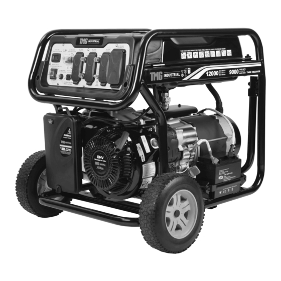
PORTABLE GASOLINE GENERATOR
Model: TMG-9000GE
TMG-12000GE
Please read the product manual completely before assembly
Check against the parts list to make sure all parts are received
Wear proper safety goggles or other protective gears while in assembly
Missing parts or questions on assembly?
Please call: 1-877-761-2819 or email: cs@tmgindustrial.com
Do not return the product to dealer, they are not equipped to handle your requests
WWW.TMGINDUSTRIAL.COM
Toll Free:1-877-761-2819
Advertisement
Table of Contents

Related Manuals for TMG TMG-9000GE


Summary of Contents for TMG TMG-9000GE
- Page 1 V2021.03.15 PRODUCT MANUAL PORTABLE GASOLINE GENERATOR Model: TMG-9000GE TMG-12000GE Please read the product manual completely before assembly Check against the parts list to make sure all parts are received Wear proper safety goggles or other protective gears while in assembly Missing parts or questions on assembly? Please call: 1-877-761-2819 or email: cs@tmgindustrial.com...
-
Page 2: Table Of Contents
TABLE OF CONTENTS Introduction……………..……………………3 Section 6- Maintenance…..……………12 Section 1-Safety Rules….……..……………3 6.1 Maintenance Schedule……………………12 Standards Index…….………………………3 6.2 General Recommendations……….………12 Section 2- General Information…..……6 6.2.1 Generator Maintenance…………………12 2.1Unpacking…………………………………….6 6.2.2 To Clean the Generator…..………10 2.2Assembly………………………………………6 6.2.3 Engine Maintenance…………………….12 Section 3-Features and Controls....…..7 6.2.4 Changing the Oil….………………………13 Section 4 - Preparation 6.2.5 Replacing the Spark Plug………………13 Before Operation….…......8... -
Page 3: Introduction
WARNING indicates a potentially INTRODUCTION hazardous situation which,if not avoided, Thank you for purchasing products could result in death or serious injury. CAUTION indicates a potentially We appreciate your business. Our generator is hazardous situation which,i not avoided, driven by a compact air-cooled engine with high may result in minor or moderate injury. - Page 4 The engine exhaust from this product, certain components in this product and WHEN STARTING EQUIPMENT related accessories contain chemicals known to · Ensure spark plug,muffler, fuel cap,and air cleaner the State of California to cause cancer, birth are in place. defects or other reproductive harm.
- Page 5 Exhaust heat/gases could ignite Excessively high operating combustibles, structures or speeds could result in minor injury and/or damage fuel tank causing a fire, generator damage. resulting in death,serious injury Excessively low speeds impose a heavy load. and/or property damage. Contact with muffler ·...
-
Page 6: Section 2-General Information
SECTION 2-GENERAL INFORMATION 2.1 UNPACKING · Set the carton on a rigid, flat surface. · Remove everything from carton except generator. · Open carton completely by cutting each corer from top to bottom. · Leave generator on carton to install wheel kit. 2.1.1 PACKTNG CONTENTS 1-Owner's Manual 2-Wheels... -
Page 7: Section 3-Features And Controls
SECTION 3 -FEATURES AND CONTROLS Read this Owner's Manual and safety rules before operating your generator. Compare the illustrations with your generator, to familiarize yourself wit the locations of various controls and adjustments. Sae this manual for future reference. Time Meter Fuel Tank Engine Switch Spark Plug... -
Page 8: Before Operation
SECTION 4-PREPARATION BEFORE OPERATION 4.1 ADDING ENGINE OIL to 15%MTBE(methyl tertiary butyl ether) is All oil should meet minimum American acceptable. Petroleum Institute(API) Service Class SJ,SL or · Do not mix oil with gasoline better. Use no special additives. Select the oil's ·... -
Page 9: Section 5- Operation
copper or brass grounding rod (electrode) provides Table Saw/Radial Am Saw 2000 2000 adequate protection against electrical hock.However, -25cm (10in) local codes may vary widely. Consult with a local Air Compressor-1HP 1600 4500 electrician for grounding requirement in the area. Proper grounding of the generator will help prevent SECTION 5 —... - Page 10 Move engine choke lever to the CHOKE position. When engine starts, move choke lever to 1/2- CHOKE position until engine runs smoothly and then fully into RUN position. If engine falters, move choke back out to 1/2-CHOKE position until engine runs smoothly and then fully into RUN position.
-
Page 11: Starting The Engine
IMPORTANT: Do not overload the generator. Also,do or decal affixed to be the device. not overload individual panel receptacles. These If the appliance, tool or motor does not give outlets are protected against overload with wattage, multiply volts times ampere rating to push-to-reset-type circuit breakers. -
Page 12: Section 6- Maintenance
SECTION 6- MAINTENANCE 6.1 MAINTENANCE SCHEDULE 6.2.1 GENERATOR MAINTENANCE Follow the calendar intervals shown below. More Generator maintenance consists of keeping the unit frequent service is required when operating in clean and dry. Operate and store the unit in a clean adverse conditions. -
Page 13: Changing The Oil
6.2.4 CHANGING THE OIL Change the oil after the first five hours of operation, then every 50 hours thereafter. If running this unit under dirty or dusty conditions, or in extremely hot weather, to change the oil more often. 6.2.6 SPARK ARRESTER ·... -
Page 14: Valve Clearance
6.4 VALVE CLEARANCE After the first 50 hours of operation, check the valve clearance in the engine and adjust if necessary. Important: If feeling uncomfortable about doing this procedure or the proper tools are not available, please take the generator to the nearest service centre to have the valve clearance adjusted. -
Page 15: Section 8-Troubleshooting
SECTION 8- TROUBLESHOOTING Problem Cause Correction Engine is running, 1. One of the circuit breakers is off. 1. Turn circuit breaker to ON. but no AC output is 2. Fault in generator. 2. Contact authorized service facility. available. 3. Poor connection or defective cord 3. -
Page 16: Section 9- Parameter
SECTION 9— PARAMETER SPECIFICATION Model TMG-9000GE TMG-12000GE Engine 14.0HP 16.0HP Displacement 420cc 459cc Rated frequency 60Hz 60Hz Rated voltage 120/240V 120/240V Running watts 7.25KW 9.0KW Starting watts 9.0KW 12.0KW Fuel tank capacity 7 Gallon 7 Gallon Fl load continuum running time 6.5H... -
Page 17: Section 10-Electric Diagram
SECTION 10— ELECTRIC DIAGRAM TMG-9000GE WWW.TMGINDUSTRIAL.COM P17/28 Toll Free:1-877-761-2819... - Page 18 TMG-12000GE WWW.TMGINDUSTRIAL.COM P18/28 Toll Free:1-877-761-2819...
-
Page 19: Section 11-Explosion Diagram & Part List
SECTION 11— EXPLOSION DIAGRAM & PART LIST (TMG-9000GE) Main Explosion Diagram WWW.TMGINDUSTRIAL.COM P19/28 Toll Free:1-877-761-2819... - Page 20 Parts No. Description QTY NO. Parts No. Description Bolt,Hexagon 30125-00026-00 Nut,Hexagon Flange,M10 35 30101-00088-00 Flange,M6*190 34030-00034-00 Shock Absorbing Mount 36 33085-00058-00 Motor Bracket/Φ190 30125-00023-00 Nut,Hexagon Flange,M8 37 20107-00021-00 Wiring Borad Assy 30136-00086-00 Flat Washer 38 30101-00329-00 Bolt,Hexagon Flange,M5*16 20134-00083-01 Wheel Assy 39 20183-00015-00 Carbon Brush 34031-00020-00 Wheel Axle 40 30101-00329-00 Bolt,Hexagon Flange,M5*16...
- Page 21 Engine Explosion Diagram WWW.TMGINDUSTRIAL.COM P21/28 Toll Free:1-877-761-2819...
- Page 22 Parts No. Description QTY NO. Parts No. Description 33580-00014-00 Flange Bolt Assy,Abnormity 43 20011-00047-00 Crankshaft Assy 20021-00004-00 Cylinder Cover Assy 44 33048-00063-00 Gasket, Crankcase Cover 34023-00021-00 Exhaust Pipe 45 34006-00001-00 Dowel Pin 33048-00028-00 Gasket, Cylinder Cap 46 30141-00116-00 Bearing 30121-00034-00 Regulating Nut 47 33129-00016-00 Crankcase Cover 30134-00005-00 Rockshaf 48 30101-00370-00 Bolt,Hexagon Flange,M8*40...
- Page 23 Control Explosion Diagram Parts No. Description QTY NO. Parts No. Description Liquid Crystal Timer Panel Oil Indicator Lamp Panel Decal Circuit Breaker Earth Stud American Duplex Socket Ac Thermal Protection Ac Thermal Protection V-Shaped DC Socket American Three-Hole Extinguishing Switch Anti-Falling Socket American Four-Hlie Socket WWW.TMGINDUSTRIAL.COM...
- Page 24 SECTION 11— EXPLOSION DIAGRAM & PART LIST (TMG-12000GE) Main Explosion Diagram WWW.TMGINDUSTRIAL.COM P24/28 Toll Free:1-877-761-2819...
- Page 25 Parts No. Description QTY NO. Parts No. Description Bolt,Hexagon 30125-00026-00 Nut,Hexagon Flange,M10 35 30101-00088-00 Flange,M6*200 34030-00040-00 Shock Absorbing Mount 36 33085-00058-00 Motor Bracket/Φ190 30125-00023-00 Nut,Hexagon Flange,M8 Wiring Board Assy 30136-00086-00 Flat Washer 38 30101-00329-00 Bolt,Hexagon Flange,M5*16 20134-00083-01 Wheel Assy Carbon Brush 34031-00020-00 Wheel Axle 40 30101-00329-00 Bolt,Hexagon Flange,M5*16 41 20044-00104-00 AVR...
- Page 26 Engine Explosion Diagram WWW.TMGINDUSTRIAL.COM P26/28 Toll Free:1-877-761-2819...
- Page 27 Parts No. Description QTY NO. Parts No. Description 30101-00071-00 Flange Bolt Assy, 42 30101-00070-00 Bolt,Hexagon Flange,M6*12 20021-00018-00 Cylinder Cover Assy 43 34021-00014-00 Wind Scooper 34023-00074-00 Exhaust Pipe 44 30141-00112-00 Bearing 33048-00154-00 Gasket, Cylinder Cap 45 20011-00063-00 Crankshaft Assy 30101-00070-00 Bolt,Hexagon Flange,M6*12 46 33048-00066-00 Gasket, Crankcase Cover 34021-00062-00 Air Deflector 47 34006-00001-00 Dowel Pin...
- Page 28 Parts No. Description QTY NO. Parts No. Description 83 20028-00029-00 Ignition Coil Assy 89 30101-00070-00 Bolt,Hexagon Flange,M6*12 84 30101-00530-00 Bolt,Hexagon Flange,M6*30 90 20010-00106-00 Starter Assy, Recoil 85 20051-00020-00 Flywheel Assy 91 34024-00024-00 Clip 86 33155-00042-00 Cooling Fan 92 34023-00083-00 Breather Pipe 87 34022-00008-00 Starting Cup 93 34024-00031-00 Clip 88 30125-00035-00 Nut,Hexagon Flange,M16...
Need help?
Do you have a question about the TMG-9000GE and is the answer not in the manual?
Questions and answers