Table of Contents
Advertisement
Quick Links
Advertisement
Table of Contents

Subscribe to Our Youtube Channel
Related Manuals for BMPRO ProBoost25


Summary of Contents for BMPRO ProBoost25
- Page 1 OWNER’S MANUAL ProBoost ProBoost25 ProBoost40 TEAMBMPRO.COM...
- Page 3 To learn more about the BMPRO range of products, please visit our website teambmpro.com TEAM BMPRO...
-
Page 4: Safety Precautions
SAFETY PRECAUTIONS Please read the Safety Precautions before installing or using the ProBoost. Be sure to observe all precautions without fail. Failure to observe these instructions properly may result in personal damage, or personal injury which depending on the circumstances may be serious and cause loss of life. It is best to have professional guidance when installing and using the charger. -
Page 6: Table Of Contents
DISCLAIMER: BMPRO accepts no liability for any loss or damage which may occur from the improper or unsafe use of its products. Warranty is only valid if the unit has not been modified Copyright ©... -
Page 8: About The Proboost
The ProBoost blends both solar and auxiliary inputs to ensure there is always a consistent charge to your battery. The ProBoost is available in two models, the ProBoost25 and the ProBoost40 to suit your charging needs. KEY FEATURES 9 Compatible with lead-acid and lithium LiFePO4 batteries ... -
Page 9: Description Of Parts
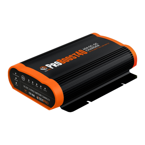
DESCRIPTION OF PARTS Figure 1: The ProBoost Battery Selection Button Used to select the battery type to be charged. Mounting Slots Used to mount the ProBoost to a surface with screws. Input/Output Leads Used to connect the ProBoost to inputs and outputs. DISPLAY PANEL Figure 2: ProBoost Display Panel... -
Page 10: Installation
Cables can be used that are equal to or larger than this size. Cable Cable Colour <5m <10m Solar Green Alternator Yellow ProBoost25: 10 AWG ProBoost25: 8 AWG ProBoost40: 8 AWG ProBoost40: 6 AWG Output Ground Black Ignition Blue... -
Page 11: Wiring Instructions
WIRING INSTRUCTIONS To wire the ProBoost: Ensure the vehicle engine is turned off. This will prevent any accidental short circuiting during the installation. NOTE: Vehicle power down may result in loss of memory data. Ensure the negative pole of the starter battery is disconnected. Connect the output cable to the positive pole of the auxiliary battery. -
Page 12: Wiring Diagram
WIRING DIAGRAM... -
Page 13: Typical Set-Up
TYPICAL SET-UP... -
Page 14: Fusing
Self-resetting circuit breakers are not recommended. These may trip prematurely due to the heat generated by the current flowing through the wires. Fuse Recommendation Cable Cable Colour ProBoost25 ProBoost40 Solar Green Alternator Yellow Output... -
Page 15: Led Indicators
LED INDICATORS LED STATUS KEY SHORT FLASH - 0.5S ON, 0.5S OFF LONG FLASH - 1S ON, 2S OFF LED CHARGE INDICATORS SOLID COLOUR The LEDs on the ProBoost will illuminate NO LIGHT to indicate the current charging stage. The flashing LED indicates the charging source (either alternator or solar). If both the alternator and solar LEDs are flashing, the charging source is from both the alternator and solar. -
Page 16: Led Fault Indicators
LED FAULT INDICATORS LED STATUS KEY If the ProBoost detects a fault, LEDs will QUICK FLASH - 0.2S ON, 1.8S OFF illuminate to indicate the fault. NO LIGHT Alternator Solar Battery Fault Fault Solution Type LED Check battery voltage Low voltage Check if the battery detected at is connected, or if... -
Page 18: Appendices
APPENDICES SPECIFICATIONS Operating Conditions ProBoost25 ProBoost40 Input Voltage 9 to 18V Solar Input Voltage 10 to 32V Maximum Input Current Input Fuse Rating Output Current Output Fuse Rating Minimum Start Voltage (Lead-Acid) Minimum Start Voltage (LiFePO4) Standby Current <15mA Battery Type... -
Page 19: Compliance
• Connect the equipment into an outlet on a circuit different from that to which the receiver is connected, • Consult the dealer or an experienced radio/TV technician for help. Warning: Any changes or modifications not expressly approved by BMPRO could void the user’s authority to operate this equipment. -
Page 20: Warranty Terms And Conditions (Australia)
WARRANTY TERMS AND CONDITIONS (AUSTRALIA) Registering your BMPRO product is an important step to ensure that you receive all the benefits you are entitled to. Please visit teambmpro.com to complete the online registration form for your new product today. BMPRO goods come with guarantees that cannot be excluded under Australian Consumer Law. -
Page 21: Limited Warranty Terms And Conditions (Usa)
• BMPRO may seek reimbursement of any costs incurred when a product is found to be in proper working order or damaged as a result of any of the warranty exclusions listed above. - Page 24 BMPRO TEAM customerservice@teambmpro.com BMPRO 19 Henderson Rd, Knoxfield VIC 3180 Australia Unit 1, 821 E Windsor Ave, Elkhart IN 46514 USA .COM teambmpro.com...
Need help?
Do you have a question about the ProBoost25 and is the answer not in the manual?
Questions and answers