Advertisement
Quick Links
Advertisement

Related Manuals for Lanner IIOT-I300


Summary of Contents for Lanner IIOT-I300
- Page 1 Industrial Embedded Platforms IIOT-I300 User Manual Version: 1.0 Date of Release:2023-02-14...
- Page 2 - assumed to be qualified in the servicing of computer equipment, such as professional system integrators, or service personnel and technicians. The latest version of this document can be found on Lanner’s official website, available either through the product page or through the Lanner Download Center page with a login account and password.
- Page 3 IIOT-I300 User Manual Taiwan Corporate Headquarters China Lanner Electronics Inc. Beijing L&S Lancom Platform Tech. Co., Ltd. 7F, No.173, Sec.2, Datong Rd. Guodong LOFT 9 Layer No. 9 Huinan Road, Xizhi District, New Taipei City 22184, Huilongguan Town, Changping District, Beijing...
- Page 4 IIOT-I300 User Manual Intel® and Intel® Celeron® are trademarks of Intel Corporation or its subsidiaries in the U.S. and/or other countries. Microsoft Windows and MS-DOS are registered trademarks of Microsoft Corp. Hailo-8 is registered trademarks of Hailo. All other product names or trademarks are properties of their respective owners.
- Page 5 IIOT-I300 User Manual Suivez ces consignes pour assurer la sécurité générale : Laissez la zone du châssis propre et sans poussière pendant et après l’installation. Ne portez pas de vêtements amples ou de bijoux qui pourraient être pris dans le châssis. Attachez votre cravate ou écharpe et remontez vos manches.
- Page 6 IIOT-I300 User Manual d’ESD surviennent lorsque des composants électroniques sont mal manipulés et peuvent causer des pannes totales ou intermittentes. Suivez les procédures de prévention d’ESD lors du retrait et du remplacement de composants. Portez un bracelet anti-ESD et veillez à ce qu’il soit bien au contact de la peau. Si aucun bracelet n’est disponible, reliez votre corps à...
- Page 7 IIOT-I300 User Manual The device can only be used in a fixed location such as a lab or a machine room. When you install the device, ensure that the protective earthing connection of the socket-outlet is verified by a skilled person.
- Page 8 IIOT-I300 User Manual Package Content..........................10 Ordering Information ........................10 System Specifications ........................11 Front Panel ............................12 Rear Panel ............................13 Motherboard Information........................ 14 Opening the Chassis ......................... 22 Installing the System Memory ......................23 Installing the mSATA Storage (Optional) ..................24 Installing the Wi-Fi Module (Optional).....................
- Page 9 IIOT-I300 User Manual Warranty Policy ..........................69...
- Page 10 IIOT-I300 User Manual The IIOT-I300 is an industrial environment gateway IPC powered by the Intel® Celeron® (Apollo Lake) processor, with 2/4 core CPU (N3350/J3455) and 3x GbE ports (depend on SKU), serial and digital I/O ports, 1x display port, 2x USB 2.0, 2x USB 3.0, 2x M.2 expansion for LTE & Wi-Fi. This wireless gateway with LTE or Wi-Fi is designed for IoT/IIoT edge, wireless security and multi-site management solution deployment in commercial, enterprise, and public sector applications.
- Page 11 IIOT-I300 User Manual SKU A/C: Intel® Celeron® N3350 (Apollo Lake) SKU B/D: Intel® Celeron® J3455 (Apollo Lake) SKU A/C: 1.1-2.4GHz Frequency SKU B/D: 1.5-2.3GHz Processor System SKU A/C: 2 cores Core Number SKU B/D: 4 cores BIOS AMI SPI Flash BIOS...
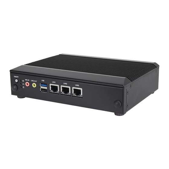
- Page 12 IIOT-I300 User Manual Description Power Button 1x Power ON/OFF switch Storage Activity LED Indicators LTE Status (Optional) System Power 1x Line-out and 1x Mic-in Audio Port USB Port 1x USB 3.0 Port and 1x USB 2.0 Port A/B SKU: 3x RJ45 GbE Ports...
- Page 13 IIOT-I300 User Manual Description Power Supply 1x 2-pin Terminal Block for DC +24V Input Serial Port 2x DB9 Male for RS232/422/485 Ports (Default RS232) DIO Port 2x6-pin Terminal Block (3.5mm) for 4x DI and 4x DO USB Port 1x USB 3.0 Port and 1x USB 2.0 Port...
- Page 14 IIOT-I300 User Manual...
- Page 15 IIOT-I300 User Manual The pin headers on the motherboard are often associated with important functions. With the shunt (Jumper) pushed down on the designated pins (the pin numbers are printed on the circuit board, surrounding the pin header), certain feature can be enabled or disable. When changing the jumpers, make sure your system is completely turned off.
- Page 16 IIOT-I300 User Manual 2. JRI1 1-2: COM1 (Default Pin 1-2) Signal Signal COM_RI1_N COM_RI1_SEL_N +P5V_S COM_RI1_SEL_N +P12V_S COM_RI1_SEL_N 3. JRI2: COM2 (Default Pin 1-2) Signal Signal COM_RI2_N COM_RI2_SEL_N +P5V_S COM_RI2_SEL_N +P12V_S COM_RI2_SEL_N 4. J3600: PMIC SMBUS (Default NC) Signal PMIC_SDA PMIC_SCL 5.
- Page 17 IIOT-I300 User Manual SPI0_CLK SPI0_MOSI 8. RST2: SW/HW Reset (Default Pin 2-3) Pin 1-2 SW Reset Pin 2-3 HW Reset Signal SIO_SW_RST_N SW_RST_BTN_N HW_RST_BTN_N 9. JCMOS1: RTC CMOS1 (Default Pin 1-2) Pin 1-2 Normal Pin 2-3 Clear RTC Signal SRTCRST_N 10.
- Page 18 IIOT-I300 User Manual 12. M2_B: M.2 B-Key Signal Signal +P3V3_M2B +P3V3_M2B F_CARD_PWROFF_N USB_D+ M2B_W_DIS_N USB_D- WWAN_LED_N Key(Notch location) Key(Notch location) Key(Notch location) Key(Notch location) Key(Notch location) Key(Notch location) Key(Notch location) Key(Notch location) M2B_GPS_DIS_N USB3_RXN UIM1_RST_R USB3_RXP UIM1_CLK_R UIM1_DAT_R USB3_TXN UIM1_PWR...
- Page 19 IIOT-I300 User Manual +P3V3_M2B +P3V3_M2B 13. SATAPWR1: SATA1 Power Connector Signal +P12V_S +P5V_S 14. SATA1: SATA Connector Signal SATA_TXP SATA_TXN SATA_RXN SATA_RXP 15. MSATA1: MSATA Connector Signal Signal +P3V3_S SATA_RXP +P3V3_S SATA_RXN...
- Page 20 IIOT-I300 User Manual SATA_TXN SATA_TXP +P3V3_S +P3V3_S +P3V3_S 16. M2_E: M.2 E-Key Signal Signal +P3V3_S USB2_D+ +P3V3_S USB2_D- LED_WLAN1_N LED_WLAN2_N Key(Notch location) Key(Notch location) Key(Notch location) Key(Notch location) Key(Notch location) Key(Notch location) Key(Notch location) Key(Notch location) PCIE_M2E_TXP PCIE_M2E_TXN PCIE_M2E_RXP PCIE_M2E_RXN...
- Page 21 IIOT-I300 User Manual PCIE_REFCLK_P PCIE_REFCLK_N M2E_SUSCLK PERST_M2E_N CLKREQ_N M2E_BT_DIS_R_N PE_WAKE_N M2E_WIFI_DIS_R_N +P3V3_S +P3V3_S 17. JBAT1: Coin Battery Connector of CR2032 Signal VBAT 18. J80PORT1 Signal Signal LPC_CLKOUT0 LPC_LAD1 80PORT_RST# LPC_LAD0 LPC_FRAME_N +P3V3_S LPC_LAD3 LPC_LAD2...
- Page 22 IIOT-I300 User Manual To reduce the risk of personal injury, electric shock, or damage to the unit, please remove all power connections to completely shut down the device, and wear ESD protection gloves when handling the installation steps. 1. Completely power off the system. Turn the system over.
- Page 23 IIOT-I300 User Manual The motherboard supports one additional system memory slot, please follow the steps for installation. 1. Power off the system, turn the system around, and open the bottom chassis cover. Locate the DIMM socket on the motherboard. 2. Align the notches of the DIMM module with the socket key in the pin slot.
- Page 24 IIOT-I300 User Manual The system supports one mSATA slot for additional memory storage. Please follow the steps for installation. 1. Power off the system, turn the system over and open the bottom chassis cover. Locate the mSATA slot on the motherboard.
- Page 25 IIOT-I300 User Manual The system supports one M.2 E-Key slot for a Wi-Fi module card. Wi-Fi module requires two antennas. Please follow the steps to install the Wi-Fi module card. 1. Power off the system, turn the system around, and open the bottom chassis cover.
- Page 26 IIOT-I300 User Manual Installing Wi-Fi Antennas Front Panel ㄉ 1. Locate the two (2) antenna hole placement (A1, A2). Locate the two (2) IPEX connectors on the Wi-Fi module. 2. Connect the RF cables to the IPEX connectors on the Wi-Fi module card and screw the other end of the cables in the antenna holes.
- Page 27 IIOT-I300 User Manual The system supports one M.2 B-Key for LTE module card expansion. LTE module requires two antennas. Please follow the procedures for installation. 1. Power off the system, turn the system around, and open the bottom chassis cover.
- Page 28 IIOT-I300 User Manual Installing LTE Antennas Rear Panel ㄉ 1. Locate the two (2) antenna hole placement (A1, A2). Locate the two (2) IPEX connectors on the LTE module. 2. Connect the RF cables to the IPEX connectors on the LTE module card and screw the other end of the cables in the antenna holes.
- Page 29 IIOT-I300 User Manual The system supports one 2.5” HDD/SSD (SSD preferred) drive bay. The following will discuss disk drive installation procedures. 1. The SSD Kit includes: 1x 2.5” SSD 1x SATA Cables 2.5” SSD SATA Cables 2. Power off the system and open the bottom chassis cover.
- Page 30 IIOT-I300 User Manual With the Wall-mount Kit, this system can be fixed on a flat surfaced wall. Please contact Lanner sales representative for purchasing this kit. Please take the following into consideration when mounting the system onto a wall. What’s in the Wall-mount Kit?
- Page 31 IIOT-I300 User Manual 4. Align the four screw holes on the system’s wall brackets with the four long screws you just installed on the wall. Engage the four screws in the bracket holes, and push the system downwards to lock the screws into position.
- Page 32 BIOS (Basic Input / Output System) is the program that controls the computer boot process. BIOS is a firmware embedded on an exclusive chip on the system’s motherboard. Lanner's BIOS firmware offering including market-proven technologies such as Secure Boot and Intel Boot Guard technology deliver solid commitments for the shield protection against malware, uncertified sequences and other named cyber threats.
- Page 33 IIOT-I300 User Manual Setup main page contains BIOS information and project version information. Feature Description BIOS Vendor: American Megatrends Core Version: AMI Kernel version, CRB code base, X64 Compliancy: UEFI version, PI version BIOS Information Project Version: BIOS release version...
- Page 34 IIOT-I300 User Manual Select the Advanced menu item from the BIOS setup screen to enter the “Advanced” setup screen. Users can select any of the items in the left frame of the screen.
- Page 35 IIOT-I300 User Manual Feature Options Description Enables or disables BIOS support for security device. By Security Device Enabled disabling this function, OS will not show Security Device. TCG Support Disabled EFI protocol and INT1A interface will not be available. Enabled Enables or disables SHA-1 PCR Bank.
- Page 36 IIOT-I300 User Manual Schedules an Operation for the Security Device. NOTE: Your None Pending operation computer will reboot during restart in order to change State TPM Clear of Security Device. Enabled Platform Hierarchy Enables or disables Platform Hierarchy. Disabled Enabled Enables or disables Storage Hierarchy.
- Page 37 IIOT-I300 User Manual...
- Page 38 IIOT-I300 User Manual Feature Options Description Disabled Serial Port Enables or disables Serial Port 1. Enabled Device Settings IO=3F8h; IRQ = 4 Loopback RS232 COM1 MODE Select Com Mode as RS232/RS485 RS485 Half Duplex RS485/422 Full-Duplex COM1 Enabled COM RS-422/485 Receiver Termination...
- Page 39 IIOT-I300 User Manual Feature Options Description Disabled Serial Port Enables or disables Serial Port 2. Enabled Device Settings IO=2F8h; IRQ = 3 Loopback RS232 COM2 MODE Select Com Mode as RS232/RS485 RS485 Half Duplex RS485/422 Full-Duplex Disabled COM2 Termination COM RS-422/485 Receiver Termination...
- Page 40 IIOT-I300 User Manual Feature Description System Temp This value reports the System temperature. CPU Temp This value reports the CPU temperature. VCORE This value reports the CPU VCORE. This value reports the 12V Input voltage This value reports the 5V Input voltage.
- Page 41 IIOT-I300 User Manual Feature Options Description Disabled Watch Dog Timer Enable or Disable Watch Dog function Enabled...
- Page 42 IIOT-I300 User Manual Feature Options Description Output High Digital I/O Pin 1 Configure Digital I/O Pin High or Low Output Low Output High Digital I/O Pin 3 Configure Digital I/O Pin High or Low Output Low Output High Digital I/O Pin 5...
- Page 43 IIOT-I300 User Manual Feature Options Description SIM-1 SIM Selector1 Select which SIM card would use SIM-2...
- Page 44 IIOT-I300 User Manual Feature Options Description Enable WWAN function GPIO OUPUT Disable Enable GPS function GPIO OUPUT Disable...
- Page 45 IIOT-I300 User Manual Feature Options Description COM0 Console Enabled Enables or disables Console Redirection Disabled Redirection COM1 Console Enabled Enables or disables Console Redirection Disabled Redirection...
- Page 46 IIOT-I300 User Manual Feature Options Description ANSI: Extended ASCII char set. VT100 VT100: ASCII char set. VT100+ Terminal Type VT100+: Extends VT100 to support color, function keys, etc. VT-UTF8 VT-UTF8: Uses UTF8 encoding to map Unicode chars onto ANSI 1 or more bytes.
- Page 47 IIOT-I300 User Manual Key Support Enabled terminals Disabled With this mode enabled only text will be sent. This is to Recorder Mode Enabled capture Terminal data. Disabled Resolution Enables or disables extended terminal resolution. 100x31 Enabled VT100 LINUX XTERM86 Putty KeyPad Select FunctionKey and KeyPad on Putty.
- Page 48 IIOT-I300 User Manual Feature Options Description Select a COM port to display redirection of Legacy OS and Redirection COM COM0 Port Legacy OPROM Messages Legacy OS 80x24 On Legacy OS, the Number of Rows and Columns Redirection 80x25 supported redirection.
- Page 49 IIOT-I300 User Manual Feature Options Description Disabled When enabled, a VMM can utilize the additional hardware Intel Virtualization Technology Enabled capabilities provided by Vanderpool Technology Disabled VT-d Enable/Disable CPU VT-d Enabled When a processor thermal sensor trips (either core), the Disabled PROCHOT# will be driven.
- Page 50 IIOT-I300 User Manual...
- Page 51 IIOT-I300 User Manual Feature Options Description Disabled Enable/Disable Intel SpeedStep EIST Enabled...
- Page 52 IIOT-I300 User Manual Feature Options Description Globally Enables or Disables 64bit capable Devices to be Disabled Above 4G Decoded in Above 4G Address Space (Only if System Enabled Decoding Supports 64 bit PCI Decoding). Disabled Re-enable Bus Master Attribute disabled during Pci...
-
Page 53: Driver Support
IIOT-I300 User Manual Feature Options Description Enables Legacy USB support. Enabled Auto option disables legacy support if no USB devices are Legacy USB Disabled connected; Support Auto Disabled option will keep USB devices available only for EFI applications. Enabled This is a workaround for OSes without XHCI hand-off support. - Page 54 IIOT-I300 User Manual Feature Options Description Disabled Enables or disables CSM Support CSM Support Enabled Do Not Launch UEFI Controls the execution of UEFI and Legacy PXE OpROM Network Legacy Do Not Launch UEFI Controls the execution of UEFI and Legacy Storage OpROM...
- Page 55 IIOT-I300 User Manual Feature Options Description Disabled LAN3 Select On Board LAN for enabled PXE boot function PXE Function LAN2 LAN1...
- Page 56 IIOT-I300 User Manual Select the Chipset menu item from the BIOS setup screen to enter the “Chipset” setup screen. Users can select any of the items in the left frame of the screen.
- Page 57 IIOT-I300 User Manual Feature Options Description 2 GB 2.25 GB Max TOLUD 2.5 GB Maximum Value of TOLUD. 2.75 GB 3 GB Enable/Disable above MemoryMappedIO BIOS Enabled Above 4GB MMIO assignment This is disabled automatically when Aperture Size BIOS assignment...
- Page 58 IIOT-I300 User Manual Feature Options Description Quiet Configure Serial IRQ Mode. Serial IRQ Mode Continuous Windows Android Select the target OS OS Selection Win7 Intel Linux...
- Page 59 IIOT-I300 User Manual...
- Page 60 IIOT-I300 User Manual...
- Page 61 IIOT-I300 User Manual Feature Options Description Enabled XHCI Pre-Boot Disabled Enabled/Disable XHCI Pre-Boot Driver support Driver Auto Once disabled, XHCI controller would be function disabled, Enabled xHCI Mode none of the USB devices are detectable and usable during boot Disabled and in OS.
- Page 62 IIOT-I300 User Manual Feature Options Description Specify what state to go to when power is re-applied after a Power On power failure (G3 state). Restore AC Power Power Off S0 State: System will boot directly as soon as power applied.
- Page 63 IIOT-I300 User Manual Select the Security menu item from the BIOS setup screen to enter the Security Setup screen. Users can select any of the items in the left frame of the screen. Feature Description If ONLY the Administrator's password is set, it only limits access...
- Page 64 IIOT-I300 User Manual Feature Options Description Disabled Secure Boot is activated when Platform Key(PK) is enrolled, Secure Boot Enabled System mode is User/Deployed, and CSM function is disabled. Secure Boot Mode - Custom & Standard, Set UEFI Secure Boot Standard...
- Page 65 IIOT-I300 User Manual Feature Options Description Disabled Allow to provision factory default Secure Boot keys when Factory keys Provision Enabled System is in Setup Mode Restore Factory None Force System to User Mode - install all Factory Default keys keys Allows the image to run in Secure Boot mode.
- Page 66 IIOT-I300 User Manual Select the Boot menu item from the BIOS setup screen to enter the Boot Setup screen. Users can select any of the items in the left frame of the screen. Feature Options Description The number of seconds to wait for setup activation key.
- Page 67 IIOT-I300 User Manual Select the Save and Exit menu item from the BIOS setup screen to enter the Save and Exit Setup screen. Users can select any of the items in the left frame of the screen. ■ Discard Changes and Exit Select this option to quit Setup without saving any modifications to the system configuration.
- Page 68 IIOT-I300 User Manual ■ Restore Defaults Restore default values for all setup options. Select “Yes” to load Optimized defaults. NOTE: The items under Boot Override may not be the same images as above, as it would depend on the devices connected to the system.
- Page 69 IIOT-I300 User Manual 1. All products are under warranty against defects in materials and workmanship for a period of one year from the date of purchase. 2. The buyer will bear the return freight charges for goods returned for repair within the warranty period;...
- Page 70 IIOT-I300 User Manual When requesting RMA service, please fill out the following form. Without this form enclosed, your RMA cannot be processed.
Need help?
Do you have a question about the IIOT-I300 and is the answer not in the manual?
Questions and answers