Table of Contents
Advertisement
Quick Links
OWNER'S GUIDE
Thru-Hull, Retractable with Valve
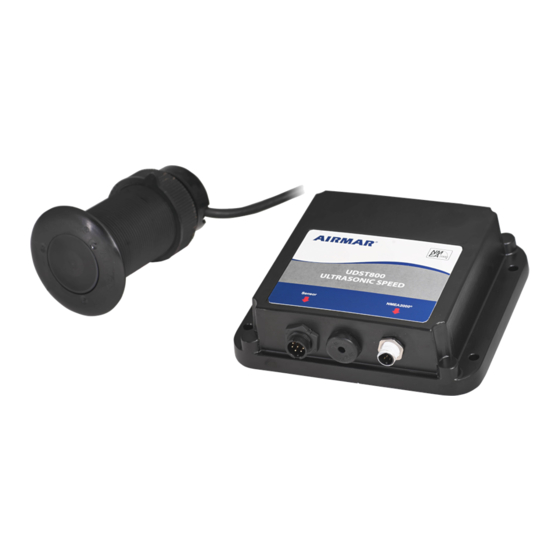
Ultrasonic TRIDUCER
Model UDST800
Follow the precautions below for optimal
product performance and to reduce the risk of
property damage, personal injury, and/or death.
WARNING: Always wear safety glasses, a dust mask,
and ear protection when installing.
WARNING: The valve is not a watertight seal!
Always install the ultrasonic insert or blanking plug. Be sure
it is fully inserted into the housing and the cap nut is screwed
on completely for a watertight seal.
WARNING: The ultrasonic insert/blanking plug must
be installed in a housing with a valve.
WARNING: The YELLOW O-ring must be in place
near the top of the insert to make a watertight seal.
WARNING: To retrofit the insert in a housing without
a valve, the insert must have a BLACK O-ring near the
top to make a watertight seal.
WARNING: The O-rings must be intact and well
lubricated to make a watertight seal.
WARNING: Stainless steel housing in a metal hull—
Be sure the washer contacts the hull. Do not tighten
the hull nut with the washer against the isolation
bushing, as the housing will not be firmly installed.
WARNING: Always attach the safety wire to prevent the
insert or blanking plug from backing out in the unlikely
event that the cap nut fails or is screwed on incorrectly.
WARNING: Immediately check for leaks when the
boat is placed in the water. Do not leave the boat
unchecked for more than three hours. Even a small
leak may allow considerable water to accumulate.
CAUTION: Plastic housing—Never use a fairing with
a plastic housing; the protruding multisensor would be
vulnerable to damage from impact.
CAUTION: Stainless steel housing in a metal hull—
Stainless steel housing must be isolated from a metal
hull to prevent electrolytic corrosion. Use the isolation
bushing supplied.
CAUTION: Metal housing—Never install a metal
housing in a vessel with a positive ground system.
CAUTION: Never pull, carry, or hold the transducer by
its cable; this may sever internal connections.
&
Multisensor
®
Smart
Sensor
™
INSTALLATION INSTRUCTIONS
Record the information found on the cable tag for future reference.
Part No._________________Date___________Frequency________kHz
U.S. Patent No.: 6,426,918; 6,671,225; 6,678,208; 9,513,373; 9,594,165
EP Patent No.: 1 634 087
CAUTION: The arrow on the top of the ultrasonic
insert must point forward toward the bow to align with
the water flow.
CAUTION: Never use solvents. Cleaner, fuel, sealant,
paint, and other products may contain solvents that can
damage plastic parts, especially the transducer's face.
IMPORTANT: Read the instructions completely
before proceeding with the installation. These
instructions supersede any other instructions in your
instrument manual if they differ.
How the Ultrasonic Speed Sensor Works
The speed sensor uses ultrasonic pulses to collect echoes from
small particles in the water as they pass under two transducers
embedded in the insert (Figure 1). These transducers monitor the
particles in their respective beams. As the boat travels through the
water, both transducers 'view' the same stream of particles.
Because it takes time for particles to travel between the two
transducers, the aft transducer detects the particles later than
does the fore transducer. By measuring this time lapse, the
instrument calculates the boat speed. If the boat is airborne, even
for a short time, or in highly aerated water, the sensor will
measure an incorrect speed.
scanning transducer
hull
vessel direction
particle stream
Figure 1. Monitoring particles in the water
Copyright © 2002 Airmar Technology Corp.
UDST800
plastic
low profile
P617V housing
FORE
AFT
Advertisement
Table of Contents

Subscribe to Our Youtube Channel
Related Manuals for Airmar TRIDUCER UDST800


Summary of Contents for Airmar TRIDUCER UDST800
- Page 1 CAUTION: Never pull, carry, or hold the transducer by its cable; this may sever internal connections. Figure 1. Monitoring particles in the water Copyright © 2002 Airmar Technology Corp.
- Page 2 30mm (1-1/4") Drill bit for pilot hole 3mm or 1/8" Figure 1. Anti-fouling paint Hole saw: Copyright © 2017 Airmar Technology Corp Plastic or metal housing in non-metal hull 51mm or 2" Stainless steel housing in metal hull 57mm or 2-1/4"...
- Page 3 Figure 3. Bedding and installing Copyright © 2017 Airmar Technology Corp Installation installed. If necessary, sand the isolation bushing until the washer rests against the hull.
- Page 4 Then lead the wire counterclockwise and through the eye in the insert. Twist the wire securely to itself. Figure 5. Replacing the O-rings Copyright © 2017 Airmar Technology Corp Installing in Housing WITHOUT Valve To create a watertight seal in a housing that does NOT have a valve, the cylinder and hull with casting epoxy.
- Page 5 (Figure 5). The remaining o-rings are placed in similar positions on the blanking plug. Replacement Multisensor & Parts The information needed to order a replacement Airmar multisensor is printed on the cable tag. Do not remove this tag. When ordering, specify the part number, date, and frequency in kHz.
- Page 6 35 Meadowbrook Drive, Milford, New Hampshire 03055-4613, USA • www.airmar.com Copyright © 2017 Airmar Technology Corp. All rights reserved.
Need help?
Do you have a question about the TRIDUCER UDST800 and is the answer not in the manual?
Questions and answers