Table of Contents
Advertisement
Advertisement
Table of Contents

Subscribe to Our Youtube Channel
Related Manuals for Extraflame 00227596


Summary of Contents for Extraflame 00227596
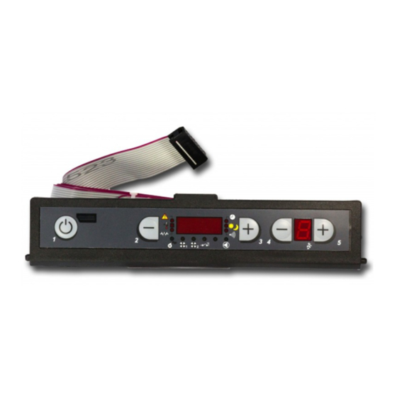
- Page 1 - Mother board - carte életronique - elektronische steuerkarte - tarjeta eletronica 00227596 - 002272575 - 00227599 M a n U a l r e S e r v e d f o r a U t H o r i S e d a f t e r - S a l e S a S S i S t a n C e S e r v i C e...
-
Page 3: Table Of Contents
INDEX Index Control Board ..................................4 Display icons key ......................................... 4 General menu ..................................5 User menU sTrUcTUre ....................................... 5 user menu....................................6 teChnICIan menu ..................................7 sTrUcTUre of The Technician menU ................................7 General DaTa ..........................................8 facTory seTTinGs ......................................... 8 DUcTeD DaTa ........................................... -
Page 4: Control Board
control BoarD control BoarD BUTTON DISplaY OF varIOUS TO aCCeSS ON/OFF TexT MeSSaGeS THe MeNU OperaTION TeMperaTUre pOWer aDJUSTMeNT SeTTING Display icons key Indicates the receipt of the radio signal On = during radio communication Indicates the status of the additional thermostat input (GND - I3) Off = no radio communication Fixed light = serial input deactivated It indicates functioning of the ducted motor... -
Page 5: General Menu
General menU User menU strUctUre Go Back - save - exit p2 p3 Browse parameters: next (p2) ; previoUs (p3) p4 p5 moDify settinG Data: increase (p4); Decrease (p5) confirm - access menU set clock set chrono on/off chrono CONFIrM lanGUaGe it,en,fr,De,es start prG1... -
Page 6: User Menu
User menU User menU Go Back - save - exit p2 p3 Browse parameters: next (p2) ; previoUs (p3) p4 p5 moDify settinG Data: increase (p4); Decrease (p5) confirm - access menU menu scrollinG text valUe fUnction Setting the day of the week MON...SUN adjustment of the hour HOUrS... -
Page 7: Technician Menu
technician Menu structure oF the technician Menu Go back - save - exit P2 P3 browse paraMeters: next (p2) ; previous (p3) P4 P5 ModiFy settinG data: increase (p4); decrease (p5) conFirM - access Menu technic set (code a0) Menu Function Allows setting a series of general parameters. -
Page 8: General Data
technician Menu General data General data FirMware COnTROls PROCeDuRe Š Press P6 and set clock will appear. PG00 Š Press P2 several times until technic set is displayed. PG01 Š Press P6. PG02 Š Hold key P4 down to reach the reserved code "A0" Š... -
Page 9: Ducted Data
technician Menu installer installer COnTROls PROCeDuRe FirMware Š Press P6 and set clock will appear. PI00 +/- 30% Š Press P2 several times until technic set is displayed. P1-5 PI01 +/- 30% Š Press P6. P1-5 Š Hold key P4 down to reach the reserved code "A0" PI02 Š... -
Page 10: Controls Active
technician Menu controls active controls active COnTROls PROCeDuRe FirMware Š Press P6 and set clock will appear. PE00 enCODeR Š Press P2 several times until technic set is displayed. PE01 Š Press P6. Š Hold key P4 down to reach the reserved code "A0" PE02 Š... -
Page 11: Alarm Memory Reset
technician Menu alarM MeMory reset COnTROls PROCeDuRe Š Press P6 and set clock will appear. Š Press P2 several times until technic set is displayed. Š Press P6. Š Hold key P4 down to reach the reserved code "A0" Š When the code has been reached, confirm by pressing P6 Š... -
Page 12: Counters Memories
technician Menu counters MeMories paraMeter COnTROls PROCeDuRe Hours p1 Š Press P6 and set clock will appear. Hours p2 Š Press P2 several times until technic set is displayed. Hours p3 Š Press P6. Š Hold key P4 down to reach the reserved code "A0" value Hours p4 Š... -
Page 13: Reset Part Hours
technician Menu reset part hours COnTROls PROCeDuRe Š Press P6 and set clock will appear. Š Press P2 several times until technic set is displayed. Š Press P6. Š Hold key P4 down to reach the reserved code "A0" Š When the code has been reached, confirm by pressing P6 Š... -
Page 14: Various Controls
various controls attivazione COnTROls PROCeDuRe Š Press P6 and set clock will appear. Š Press P2 several times until technic set is displayed. Š Press P6. Š Hold key P4 down to reach the reserved code "A0" Š When the code has been reached, confirm by pressing P6 Š... -
Page 15: Alarms
alarMs display explanation solution On: indicates the presence of an alarm Off: indicates the absence of alarms Flashing: indicates the deactivation of the depression sensor. indicates the presence of an alarm. The alarm can be reset by pressing key 1 for 3 seconds only if the fumes motor has stopped and if 15 minutes have passed from displaying the same alarm. -
Page 16: Displays
displays display reason stove off start The start phase is in progress pellet FeedinG The feeding of the pellet during the ignition phase is in progress iGnition The ignition phase is in progress start-up The start phase is in progress work The normal work phase is in progress Modulation... -
Page 17: Components
components A smAll photogrAphic key, AccompAnied by A brief description, hAs been reAlised to eAse recognition of the electric components. Attention!!! the compAny reserves the right to replAce components with others hAving equAl or improved feAtures without prior notice! we recommend referring to the exploded views AvAilAble At our website for spAre pArt requests!!! displAy The displays allow to make adjustments to the product, control the correct functioning by displayed messages. - Page 18 components A smAll photogrAphic key, AccompAnied by A brief description, hAs been reAlised to eAse recognition of the electric components. Attention!!! the compAny reserves the right to replAce components with others hAving equAl or improved feAtures without prior notice! we recommend referring to the exploded views AvAilAble At our website for spAre pArt requests!!! ducting fAn Some products have a fan available for ducting the hot air.
- Page 19 components A smAll photogrAphic key, AccompAnied by A brief description, hAs been reAlised to eAse recognition of the electric components. Attention!!! the compAny reserves the right to replAce components with others hAving equAl or improved feAtures without prior notice! we recommend referring to the exploded views AvAilAble At our website for spAre pArt requests!!! dAmpers remote control Allows to communicate with the appliance circuit board, sending commands to be followed.
- Page 20 components A smAll photogrAphic key, AccompAnied by A brief description, hAs been reAlised to eAse recognition of the electric components. Attention!!! the compAny reserves the right to replAce components with others hAving equAl or improved feAtures without prior notice! we recommend referring to the exploded views AvAilAble At our website for spAre pArt requests!!! ultrAwAtt cArtridge The ign-plug is just a heating resistor: once powered, it can develop a temperature that allows to cause a flame.
- Page 21 components A smAll photogrAphic key, AccompAnied by A brief description, hAs been reAlised to eAse recognition of the electric components. Attention!!! the compAny reserves the right to replAce components with others hAving equAl or improved feAtures without prior notice! we recommend referring to the exploded views AvAilAble At our website for spAre pArt requests!!! debimeter This sensor develops the depression inside the appliance.
-
Page 22: Maintenance
Maintenance cleaning The images are for illustration purposes. They could be offset from the original models. ScraperS Burn pot: Remove the burn pot from the relevant compartment and free the Use the scrapers, using an upward movement (for models with upper scrapers) or pulling and pushing the same (for the inserts and models holes using the appropriate fire irons supplied, remove the ash with front scrapers). - Page 23 Before eMptying it in a Special container.*the “chiMney Sweep” Bin iS an acceSSory that can Be requeSted froM the coMpany. for further inforMation, contact info@extraflaMe.it. the iMageS are for illuStration purpoSeS only.
-
Page 24: Maintenance
Maintenance poSitioning ultrawatt cartridge To adjust the resistance always follow the rule: Place the resistance to zero with the compass in the rear (Figure 1). Then verify that the distance between the opposite end of the resistance and holding tube resistance is equal to or greater than 12 mm (Figure 2). In the case where the proportion is less than 12 mm, the resistance must be moved back up to guarantee the required minimum 12 mm (Figure 1). -
Page 25: Components Compatibility
COMPONeNTS COMPATIBILITy Key: CIRCUIT BOARD VeRSIONS circuit board without room thermostat probe BOARD A : (code 002272501 - 002272512) circuit board with room thermostat probe BOARD B : (code 002272521) circuit board with room thermostat probe with 14.7 MHz quartz BOARD C : (code 002272543 - 002272552) flash type circuit board with integrated microprocessor, 14.7 MHz quartz and room thermostat... - Page 26 COMPONeNTS COMPATIBILITy COMPATIBILITy BOARD MICROPROCeSSOR SyNOPTIC...
- Page 28 Extraflame reserves the right to vary the features and data given in this document at any time without forewarning, in order to improve its products. This manual cannot be considered as a contract for third parties. www.extraflame.it/support...
Need help?
Do you have a question about the 00227596 and is the answer not in the manual?
Questions and answers