
Related Manuals for cytiva UV-900


Summary of Contents for cytiva UV-900
- Page 1 Monitor UV-900 Operating Instructions Original instructions Translation disc included cytiva.com...
- Page 2 Page intentionally left blank...
-
Page 3: Table Of Contents
Service displays ............................. 61 Changing flow cell ............................62 UV cell calibration ............................63 Restart after power failure ......................... 68 Maintenance ....................... 69 Cleaning before planned service ......................70 Cleaning the instrument housing ......................71 Monitor UV-900 Operating Instructions 28962214 AF... - Page 4 Regulations for North America ....................... 96 8.4.5 Regulatory statements ..........................97 8.4.6 Declaration of Hazardous Substances (DoHS) ................98 Health and Safety Declaration Form ...................... 100 Accessories and spare parts ........................102 Ordering information ........................... 104 Monitor UV-900 Operating Instructions 28962214 AF...
-
Page 5: Introduction
1 Introduction Introduction About this chapter This chapter contains important user information, descriptions of safety notices, intended use of the Monitor UV-900 system, and lists of associated documentation. In this chapter Section See page About this manual Important user information... -
Page 6: About This Manual
Purpose of the Operating Instructions The Operating Instructions provides you with the instructions needed to handle Monitor UV-900 in a safe way. Typographical conventions Software items are identified in the text by bold italic text. Hardware items are identified in the text by bold text. -
Page 7: Important User Information
Intended use Monitor UV-900 is a UV-absorption monitor for use in liquid chromatograhy. Monitor UV-900 is intended for research use only, and shall not be used in any clinical procedures, or for diagnostic purposes. Prerequisites In order to operate Monitor UV-900 in the way it is intended: •... - Page 8 Notes and tips Note: A note is used to indicate information that is important for trouble-free and optimal use of the product. Tip: A tip contains useful information that can improve or optimize your proce- dures. Monitor UV-900 Operating Instructions 28962214 AF...
-
Page 9: User Documentation
1.3 User documentation User documentation In addition to these Operating Instructions, the documentation package supplied with Monitor UV-900 also includes product documentation binders containing detailed specifications and traceability documents. The most important documents in the document package with regard to technical aspects of Monitor UV-900 are listed below. -
Page 10: Safety Instructions
2 Safety instructions Safety instructions About this chapter This chapter describes safety compliance, safety labels, general safety precautions, emergency procedures and power failure of Monitor UV-900. In this chapter Section See page Safety precautions Labels Emergency procedures Monitor UV-900 Operating Instructions 28962214 AF... -
Page 11: Safety Precautions
Safety precautions Introduction The Monitor UV-900 is powered by mains voltage and handles pressurized liquids that may be hazardous. Before installing, operating or maintaining the monitor, you must be aware of the hazards described in this manual. Follow the instructions provided to avoid personal injury or damage to the equipment. - Page 12 2 Safety instructions 2.1 Safety precautions WARNING Do not use Monitor UV-900 if it is not working properly, or if it has suffered any damage, for example: • damage to the power cord or its plug • damage caused by dropping the equipment •...
- Page 13 The power cord with plug must always be easy to disconnect. WARNING High intensity UV light. This product uses high intensity ultra- violet light. Do not disconnect the optical fibers while the lamp is Monitor UV-900 Operating Instructions 28962214 AF...
- Page 14 WARNING Use only approved parts. Only spare parts and accessories that are approved or supplied by Cytiva may be used for maintaining or servicing the product. Monitor UV-900 Operating Instructions 28962214 AF...
- Page 15 (e.g., NaOH) and distilled water before service and mainte- nance. WARNING Disconnect power. Always disconnect power from the instru- ment before replacing any component on the instrument, unless stated otherwise in the user documentation. Monitor UV-900 Operating Instructions 28962214 AF...
-
Page 16: Labels
2.2 Labels Labels Introduction This section describes the system label on Monitor UV-900 and its meaning. System label The system label is located on the back of the equipment. The system label identifies the equipment and shows electrical data, regulatory compliance, and warning symbols. -
Page 17: Emergency Procedures
2.3 Emergency procedures Emergency procedures Introduction This section describes how to perform an emergency shutdown of Monitor UV-900. The section also describes the result in the event of power failure. Emergency shutdown In an emergency situation, do as follows to stop the run: Switch off power to the instrument by switching the On/off switch on the rear panel to the (O) position. -
Page 18: System Description
3 System description System description Monitor UV-900 is a UV-absorption monitor for use in liquid chromatography. Monitor UV-900 features: • Variable wavelength for detection in the range 190–700 nm. • Up to 3 wavelengths can be monitored simultaneously. • Two alternative flow cells with path length 2 mm and 10 mm. -
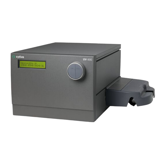
Page 19: Illustrations
3 System description 3.1 Illustrations Illustrations Main unit Part Function Display Menu selection dial Cell holder Flow cell Monitor UV-900 Operating Instructions 28962214 AF... - Page 20 Analogue output 0-1 V. Recorder output, 3 channels 0 to 1 V Remote. Digital signal inputs, lamp on/off, autozero, event mark. Uninet 1. Computer network. Mains power inlet. Supply voltage, grounded. On/off. Instrument power switch. Monitor UV-900 Operating Instructions 28962214 AF...
-
Page 21: Flow Cell
The long path length combined with a small cell volume increases sensitivity. Optional flow cells The following flow cells can also be used with Monitor UV-900: • UV cell, 1/2/5 mm (ÄKTApilot™) • Industrial flow cell 8 mm (tubing i.d. 8 mm) •... -
Page 22: Monitor Principle
3 System description 3.3 Monitor principle Monitor principle Functional diagram of the UV monitor Part Function Flash lamp 100 Hz Condensor Blocking filter Aberration corrected holographic grating Monochromator Beam splitter Reference Monitor UV-900 Operating Instructions 28962214 AF... - Page 23 Calibration At calibration the instrument automatically finds two persistent lines in the spectrum of Xenon. The wavelengths of these known lines are used to calibrate the stepper motor that turns the grating. Monitor UV-900 Operating Instructions 28962214 AF...
-
Page 24: Installation
4 Installation Installation About this chapter This chapter provides required information to enable users and service personnel to unpack, install, move and transport Monitor UV-900. Precautions WARNING Before attempting to perform any of the procedures described in this chapter, you must read and understand all contents of the... -
Page 25: Unpacking
If any damage is found, document the damage, and contact your local Cytiva representative. It is recommended that all packing materials should be retained if onward transport of the instrument is expected. Monitor UV-900 Operating Instructions 28962214 AF... -
Page 26: Site Requirements
Do not use any soft material under the instrument, to ensure that the ventilation inlet in the front is not blocked. The instrument should not be used in a corrosive atmosphere or in an atmosphere where deposits are liable to form on the optical surfaces. Monitor UV-900 Operating Instructions 28962214 AF... -
Page 27: Transport
4 Installation 4.3 Transport Transport Before moving the equipment: disconnect all connected cables and tubing. Monitor UV-900 Operating Instructions 28962214 AF... -
Page 28: Assembly
4 Installation 4.4 Assembly Assembly The following parts must be added to Monitor UV-900 before use: • Flow cell • Optical fibers • Tubing Fixing UV Flow Cell 2 mm and UV Flow Cell 10 mm NOTICE To avoid damaging the optical fibers, press only on the cell body, never on the optical fibers. - Page 29 4 Installation 4.4 Assembly Step Action Slide the rear white clip on the cell holder to its inner position for a 2 mm cell and to its outer position for a 10 mm cell. Monitor UV-900 Operating Instructions 28962214 AF...
- Page 30 Do not touch the tips of the optical fibers with your fingers as this will result in poor monitor performance. If you accidentally touch the optical fiber tip, it can be wiped with 30% isopropanol using lens papers. Monitor UV-900 Operating Instructions 28962214 AF...
- Page 31 Remove the two black protective caps from the optical fiber connectors. Remove the two rubber protective caps from the optical fiber receptacles on the right side of the housing. Part Function Protective cap Black heat shrink tubing Rubber sleeve Monitor UV-900 Operating Instructions 28962214 AF...
- Page 32 Slide the rubber sleeves on the two optical fibers onto the connectors. Make sure that the sleeves are pushed tight to the housing to prevent dust, fluid or light entering the connection. Monitor UV-900 Operating Instructions 28962214 AF...
- Page 33 Remove the red protective caps from the inlet and outlet of the flow cell. The inlet is on the top of the flow cell, the same side as the serial number. Connect the tubing with 1/16" fingertight connectors. Monitor UV-900 Operating Instructions 28962214 AF...
- Page 34 Mount the cell holder cover by pushing it onto the cell holder. Fit the two small lugs on the cover in the holes at the sides of the cell holder. Lower the cover over the cell holder. Monitor UV-900 Operating Instructions 28962214 AF...
-
Page 35: Connecting Electrical Cables
Any computer used with the equipment must comply with IEC 60950 or IEC 62368-1 and be installed and used according to the manufacturer's instructions. Connect any auxiliary equipment to the Remote socket, 9-pole D–Sub female (5 V TTL signals only). Monitor UV-900 Operating Instructions 28962214 AF... - Page 36 PC and the termination plug. The UniNet-1 link connects, in series, the PC with Pump P-905, Monitor pH/C-900 and Monitor UV-900. The termination plug is connected to the last instrument in the chain. Connecting to supply voltage...
-
Page 37: Operation
5 Operation Operation About this chapter This chapter provides the information required to safely operate Monitor UV-900. Precautions WARNING Before attempting to perform any of the procedures described in this chapter, you must read and understand all contents of the... -
Page 38: Starting The Instrument
Another message, displaying the calibrated cell length, also appears. The display toggles between these messages. To go to the main operating menu, press OK or wait for about 45 seconds to return automatically. Monitor UV-900 Operating Instructions 28962214 AF... -
Page 39: Reading Absorbance Values
The display for the third wavelength is reached by turning the dial clockwise. As an alternative, all 3 wavelengths can be shown in a single display, but limited to 3 decimals. This alternative is reached by turning the dial clockwise. Monitor UV-900 Operating Instructions 28962214 AF... -
Page 40: Menu Selection And Settings
Setting wavelength 5.3.7 Autozero 5.3.8 Setting analog output to an external chart recorder 5.3.9 Event mark 5.3.10 Noise filtering 5.3.11 Check menu 5.3.12 Setup menu 5.3.13 Setting and using the alarm timer 5.3.14 Service displays Monitor UV-900 Operating Instructions 28962214 AF... -
Page 41: Moving Between Menus
Press OK button to select sub-menu. Press ESC button to return one menu level. If a menu has sub levels, the sub menu is displayed by pressing the OK button. Pressing the ESC button moves back one menu level. Monitor UV-900 Operating Instructions 28962214 AF... - Page 42 Main menu 1 Main menu 2 Sub menu 2.1 Sub menu 2 .1.1 Main menu 3 Sub menu 2.2 Main menu 4 Sub menu 2.3.1 Sub menu 2.3 Main menu 5 Sub menu 2.3.2 Monitor UV-900 Operating Instructions 28962214 AF...
-
Page 43: Return To Main Menu
Pressing ESC repeatedly, always returns to the Main menu 2 which is the main oper- ating menu. Press ESC once more to return to Main menu 1, the mode changing menu. Main menu 1 Main menu 2 Monitor UV-900 Operating Instructions 28962214 AF... -
Page 44: Select Value
The text or numerical value displayed is accepted by pressing the OK button. To cancel, press the ESC button. Monitor UV-900 Operating Instructions 28962214 AF... -
Page 45: Main Menu Overview
Setting and using the alarm timer, on page 59. Note: The instrument has service displays for use by authorised service personnel. If the service display Enter Access Code! is accidentally selected, press the ESC button to exit to the normal operation display. Monitor UV-900 Operating Instructions 28962214 AF... -
Page 46: Setting Lamp On And Off
The lamp is switched on when a run is started. No warm-up time is required. Step Action Select the Mode changing menu. Switch the lamp on (Run) or off (End) by pressing OK. Its current status is shown in the upper left of the display. Monitor UV-900 Operating Instructions 28962214 AF... -
Page 47: Setting Wavelength
If only one wavelength is to be used, λ 1 can never be set to off. The first wavelength λ 3. Repeat step 4 in the menu Set Wavelength Press ESC to return to the main operating menu. Monitor UV-900 Operating Instructions 28962214 AF... -
Page 48: Autozero
All three wavelengths are autozeroed. Autozero is recommended after wave- length changes in a method and before the sample is injected. Step Action Select main menu Autozero. Press OK. The normal absorbance value display is then shown. Monitor UV-900 Operating Instructions 28962214 AF... -
Page 49: Setting Analog Output To An External Chart Recorder
Select menu Set Zero Level, press OK. This value determines where the zero absorbance level should be in relation to full scale on the recorder. Use the arrow keys to set the value and press OK. Monitor UV-900 Operating Instructions 28962214 AF... - Page 50 0 V and give an accurate display of the peak starting from this position. Part Function Measured absorbance level (absorbance units) Overrange Maximum range (absorbance units) Signal to recorder (V) Monitor UV-900 Operating Instructions 28962214 AF...
-
Page 51: Event Mark
The spikes are 10% of the full scale of the chart recorder which corresponds to 0.1 V. Select main menu Event mark, press OK, to insert an event mark. Monitor UV-900 Operating Instructions 28962214 AF... -
Page 52: Noise Filtering
Time constant (s) Min. peak width at half (approximate) height (s) 5.12 2.56 1.28 0.64 0.32 0.16 0.05 0.08 0.03 In UNICORN the averaging time is set with the instruction AveragingTime in System Control →Manual →Alarm&Mon. Monitor UV-900 Operating Instructions 28962214 AF... -
Page 53: Check Menu
See Section 6.5 Checking the instrument, on page 74. Checking the wavelength If there is any doubt that the instrument is showing the correct values, the wavelength calibration can be checked. Step Action Select menu Check, press OK. Monitor UV-900 Operating Instructions 28962214 AF... - Page 54 Wavelengths not OK Recalibrate? Note: If a deviation in wavelength occurs repeatedly when checked, contact Cytiva. Recalibrate If the instrument is left switched on for a long period (> 10 days), it may be necessary to recalibrate it. This calibration is identical to that done when the instrument is switched...
- Page 55 The service telephone number is displayed. Turn the selection dial clockwise to view the next display. Telephone Service 012345678901 The service contract number is displayed. Turn the selection dial clockwise to view the next display. Contract Number 012345678901 Monitor UV-900 Operating Instructions 28962214 AF...
- Page 56 The date of the last service is displayed. Turn the selection dial clockwise to view the next display. Date of Maintenance Press OK to test the instrument buzzer. Buzzer Test. Press Esc to return to the Check Service Mode menu. Monitor UV-900 Operating Instructions 28962214 AF...
-
Page 57: Setup Menu
Select sub menu Setup Unit Number, press OK. Setup Unit Number Select unit number (0 to 25). Setup display angle The display angle can be set to compensate for different viewing heights. Step Action Select main menu Setup, press OK. Monitor UV-900 Operating Instructions 28962214 AF... - Page 58 5.3 Menu selection and settings 5.3.12 Setup menu Step Action Select sub menu Set Display Angle, press OK. Setup Display Angle Select viewing angle (-> \ Up, -> | Mid, or -> / Down). Monitor UV-900 Operating Instructions 28962214 AF...
-
Page 59: Setting And Using The Alarm Timer
When the alarm time is due or the count-down timer reaches 00:00:00, an alert display is shown and the instrument beeps, until the OK button is pressed. Bzz12:41:29 12:41:49 ! ! Alarm time ! Monitor UV-900 Operating Instructions 28962214 AF... - Page 60 Clock menu placed after the Alarm/Timer menu. The clock will be reset when power is turned OFF. Set Clock 00:32:22 (00:36:53) An already set alarm/timer function can be reset by pressing OK in the menu Alarm/ Timer off?. Alarm/Timer off? (Bzz 05:33:00) Monitor UV-900 Operating Instructions 28962214 AF...
-
Page 61: Service Displays
The instrument has service displays for use by authorised service personnel. If the service display Enter Access Code! is accidentally selected, press the ESC button to exit to the normal operation display. Enter Access Code! Monitor UV-900 Operating Instructions 28962214 AF... -
Page 62: Changing Flow Cell
10 mm to 2 mm when a lower sensitivity is desired, due to output signal limitation. See Section 4.4 Assembly, on page 28. Monitor UV-900 Operating Instructions 28962214 AF... -
Page 63: Uv Cell Calibration
The display automatically returns to the main operating menu after about 45 seconds, or if pressing Instructions for removing an old calibration setting Follow these steps in order to remove an old calibration value: Monitor UV-900 Operating Instructions 28962214 AF... - Page 64 Make sure that the Flow restrictor is connected in the flow path after the UV flow cell. Mount the Union Luer female/ 1/16" male, included in the test kit, in the upper inlet of the UV flow cell. Monitor UV-900 Operating Instructions 28962214 AF...
- Page 65 5.5 UV cell calibration Step Action ® Open the UV-900 Cell Calibration Excel file on the computer. The solution bottles are marked with the concentration value and the refer- ence absorbance value for each solution. Enter the concentration of the solutions in increasing order in the column UV Test kit Concentration (mg/l).
- Page 66 After each injection, wait for a stable absorbance value and enter the meas- ured values in the Excel column UV -900 Absorbance (AU) in the UV-900 Cell Calibration Excel file. When all absorbance values have been entered, the real cell length is shown next to the Real cell length Excel cell.
- Page 67 5 Operation 5.5 UV cell calibration Step Action Enter the serial number of the cell (see the label on the flow cell). Press OK. Monitor UV-900 Operating Instructions 28962214 AF...
-
Page 68: Restart After Power Failure
If the power supply to the instrument is interrupted, the instrument automatically restarts itself and displays the main operating window. All set values are retained in the instrument but the instrument starts with the lamp switched-off. Monitor UV-900 Operating Instructions 28962214 AF... -
Page 69: Maintenance
6 Maintenance Maintenance About this chapter This chapter provides required information to enable users and service personnel to clean and maintain the Monitor UV-900. The instrument contains no internal user replaceable parts. Precautions WARNING Before attempting to perform any of the procedures described in... -
Page 70: Cleaning Before Planned Service
Health and safety declaration forms Health and safety declaration forms are available for copying or printing in the Refer- ence information chapter of this manual, or on digital media supplied with the user documentation. Monitor UV-900 Operating Instructions 28962214 AF... -
Page 71: Cleaning The Instrument Housing
Wipe the instrument housing regularly with a damp cloth. Do not allow spilled liquid to dry on the instrument. Remove dirt from the surface using a cloth and a mild cleaning agent. Let the instrument dry completely before using it. Monitor UV-900 Operating Instructions 28962214 AF... -
Page 72: User Maintenance Schedule
74. Every 6 months or more Clean the flow cell and optical fiber connectors. See often if required Section 6.6 Cleaning the flow cell and optical connec- tors, on page 76. Monitor UV-900 Operating Instructions 28962214 AF... -
Page 73: Cleaning-In-Place
At higher pressures the flow cell may break. Pump a cleaning or sanitizing agent through the flow cell. The standard recommenda- tion is to pump 1 M NaOH at 1 mL/min for 30 minutes and then wash out with buffer. Monitor UV-900 Operating Instructions 28962214 AF... -
Page 74: Checking The Instrument
Lamp intensity Step Action Select menu Check, press OK. Select menu Check Lamp Intensity. If the lamp intensity is less than 20%, contact Cytiva for lamp replacement or change of internal optical fiber. Lamp on-time Step Action Select menu Check, press OK. - Page 75 Step Action Select menu Check Flip Time. If the flip time is more than 2000 hours, contact Cytiva for maintenance. UV flow cell This menu shows the set path length and the serial number of the UV flow cell. Step Action Select menu Check, press OK.
-
Page 76: Cleaning The Flow Cell And Optical Connectors
After five squirts, leave the detergent solution in the flow cell for at least 20 minutes. Pump the remaining detergent solution through the flow cell. Rinse the syringe and flush the cell with distilled water (10 mL). Monitor UV-900 Operating Instructions 28962214 AF... - Page 77 6 Maintenance 6.6 Cleaning the flow cell and optical connectors Cleaning the optical fiber connectors When required, wipe the optical fiber connectors with 30% isopropanol on lens paper. Monitor UV-900 Operating Instructions 28962214 AF...
-
Page 78: Storage
The flow cell can also be stored dry by flushing as above with distilled water and then blowing a compressed inert gas such as nitrogen (N ) through the cell. Replace the protective caps. Never use compressed air as this may contain droplets of oil. Monitor UV-900 Operating Instructions 28962214 AF... -
Page 79: Troubleshooting
This chapter provides information required to enable users and service personnel to identify and correct problems that may occur when operating Monitor UV-900. If the suggested actions in this guide do not solve the problem, or if the problem is not covered by this guide, contact your Cytiva representative for advice. - Page 80 NaOH, and distilled water before service and maintenance. WARNING Electrical shock hazard. All repairs should be done by service personnel authorized by Cytiva. Do not open any covers or replace parts unless specifically stated in the user documentation. Monitor UV-900 Operating Instructions 28962214 AF...
-
Page 81: General
7 Troubleshooting 7.1 General General When contacting Cytiva for support, state the program version of the instrument, which is shown for 2 seconds after the selftest, during switch-on, or in the menu Check Service Mode. Monitor UV-900 Operating Instructions 28962214 AF... -
Page 82: Faults And Actions
7 Troubleshooting 7.2 Faults and actions Faults and actions If the suggested actions do not correct the fault, call Cytiva. Fault Possible cause Corrective action No text on the front No power to the monitor Check that the mains display... - Page 83 Check the chart recorder recorder set up in accordance with its manual Monitor UV-900 not Test the recorder func- properly set up tion by selecting recorder test according to Check Analogue Out, on page Monitor UV-900 Operating Instructions 28962214 AF...
-
Page 84: Error Messages
7 Troubleshooting 7.3 Error messages Error messages If the suggested actions do not correct the fault, call Cytiva. Message Description/Action Sample fiber failure Check the connections of the UV cell optical fibers. Check the liquid. Make sure that there are no air bubbles in the system. -
Page 85: Reference Information
This chapter provides technical reference information and a list of spare parts and accessories for Monitor UV-900. In this chapter Section See page Menu overview Technical specifications Procedures for decommissioning Regulatory information Health and Safety Declaration Form Accessories and spare parts Ordering information Monitor UV-900 Operating Instructions 28962214 AF... -
Page 86: Menu Overview
8 Reference information 8.1 Menu overview Menu overview The illustration below shows the full menu tree of Monitor UV-900. Monitor UV-900 Operating Instructions 28962214 AF... -
Page 87: Technical Specifications
Measured with water at 1 mL/min, time constant 1 second, 10 mm flow cell. Typical values at room temperature after 2 hours with lamp on. Physical data Light source Xenon flash lamp Monitor UV-900 Operating Instructions 28962214 AF... - Page 88 Cell volume, 2 mm cell 2 μL Cell volume, 10 mm cell 8 μL Wetted materials PTFE (polytetrafluoroethylene) PEEK (polyetheretherketone) Titanium (palladium alloy) Quartz (synthetic fused silica) pH stability range 1–13, 13–14 (< 1 days exposure) Monitor UV-900 Operating Instructions 28962214 AF...
- Page 89 The wetted parts are resistant to organic solvents and salt buffers commonly used in chromatog- raphy of biomolecules, except 100% Ethyl acetate, 100% Hexane, and 100% Tetrahydrofuran (THF). Tubing connections UNF 10-32 fingertight connectors for capillary tubing with 1/16” outer diameter Monitor UV-900 Operating Instructions 28962214 AF...
-
Page 90: Procedures For Decommissioning
8 Reference information 8.3 Procedures for decommissioning Procedures for decommissioning Introduction This section contains information about the decommissioning of Monitor UV-900. Decontamination The product must be decontaminated before decommissioning. All local regulations must be followed with regard to scrapping of the equipment. -
Page 91: Regulatory Information
Section See page 8.4.1 Contact information 8.4.2 European Union and European Economic Area 8.4.3 Eurasian Economic Union Евразийский экономический союз 8.4.4 Regulations for North America 8.4.5 Regulatory statements 8.4.6 Declaration of Hazardous Substances (DoHS) Monitor UV-900 Operating Instructions 28962214 AF... -
Page 92: Contact Information
The table below summarizes the required manufacturing information. Requirement Information Name and address of manufacturer Cytiva Sweden AB Björkgatan 30 SE 751 84 Uppsala Sweden Telephone number of manufacturer + 46 771 400 600 Monitor UV-900 Operating Instructions 28962214 AF... -
Page 93: European Union And European Economic Area
• used according to the Operating Instructions or user manuals, and • used in the same state as it was delivered, except for alterations described in the Operating Instructions or user manuals. Monitor UV-900 Operating Instructions 28962214 AF... -
Page 94: Eurasian Economic Union
I, room 57 Telephone: +7 495 7877617 E-mail: rucis@cytiva.com Информация о производителе и импортере В следующей таблице приводится сводная информация о производителе и импортере, согласно требованиям Технических регламентов Таможенного союза и (или) Евразийского экономического союза. Monitor UV-900 Operating Instructions 28962214 AF... - Page 95 Member States of the Customs Union of the Eurasian Economic Union Данный знак о Евразийском соответствии указывает, что изделие одобрено для использования на рынках государств-членов Таможенного союза Евразийского экономического союза Monitor UV-900 Operating Instructions 28962214 AF...
-
Page 96: Regulations For North America
Note: The user is cautioned that any changes or modifications not expressly approved by Cytiva could void the user’s authority to operate the equip- ment. This equipment has been tested and found to comply with the limits for a Class A digital device, pursuant to part 15 of the FCC Rules. -
Page 97: Regulatory Statements
When used in a residential environment, there is a concern of radio interference. 주의사항 A급 기기 (업무용 방송통신 기자재) 이 기기는 업무용환경에서 사용할 목적으로 적합성평가를 받 은 기기 로서 가정용 환경에서 사용하는 경우 전파간섭의 우려가 있습 니다. Monitor UV-900 Operating Instructions 28962214 AF... -
Page 98: Declaration Of Hazardous Substances (Dohs)
Periodic replacement of those consumables or parts to maintain the declared EFUP shall be done in accordance with the Product Maintenance Procedures. This product must not be disposed of as unsorted municipal waste, and must be collected sepa- rately and handled properly after decommissioning. Monitor UV-900 Operating Instructions 28962214 AF... - Page 99 Indicates that this hazardous substance contained in at least one of the homogeneous materials used for this part is above the limit requirement in GB/T 26572 • Data listed in the table represents best information available at the time of publication. Monitor UV-900 Operating Instructions 28962214 AF...
-
Page 100: Health And Safety Declaration Form
Service Ticket #: To make the mutual protection and safety of Cytiva service personnel and our customers, all equipment and work areas must be clean and free of any hazardous contaminants before a Service Engineer starts a repair. To avoid delays in the servicing of your equipment, complete this checklist and present it to the Service Engineer upon arrival. - Page 101 To make sure the mutual protection and safety of Cytiva personnel, our customers, transportation personnel and our environment, all equipment must be clean and free of any hazardous contaminants before shipping to Cytiva. To avoid delays in the processing of your equipment, complete this checklist and include it with your return.
-
Page 102: Accessories And Spare Parts
18632405 UV-900 Cell calibration Excel-file 18632406 Tubing and connectors Item Quantity per Code no. pack FEP tubing, i.d. 1/8", o.d. 3/16" 18111247 Tubing connector for 3/16" o.d. tubing 18111249 Ferrule for 3/16" tubing 18111248 Monitor UV-900 Operating Instructions 28962214 AF... - Page 103 PEEK tubing, i.d. 1.0 mm, o.d. 1/16" 18111583 ETFE tubing, i.d. 0.25 mm, o.d. 1/16" 18112136 ETFE tubing, i.d. 0.75 mm, o.d. 1/16" 18111254 Fingertight connector 1/16" 18111255 Tools Item Quantity per Code no. pack Fiber detachment tool 18111116 Monitor UV-900 Operating Instructions 28962214 AF...
-
Page 104: Ordering Information
8 Reference information 8.7 Ordering information Ordering information For ordering information visit: cytiva.com/akta Monitor UV-900 Operating Instructions 28962214 AF... - Page 105 Page intentionally left blank...
- Page 106 © 2020–2021 Cytiva All goods and services are sold subject to the terms and conditions of sale of the supplying company operating within the Cytiva business. A copy of those terms and conditions is available on request. Contact your local Cytiva representative for the most current information.
Need help?
Do you have a question about the UV-900 and is the answer not in the manual?
Questions and answers