
Subscribe to Our Youtube Channel
Summary of Contents for Mi Swaco TOGA
- Page 1 Installation, Operation and Maintenance Manual For TOGA* Total Gas Containment System Manual Part Number: 90‐90‐885 (Rev. B) ...
- Page 2 DISCLAIMER Recommendations made by M‐I SWACO are advisory only. M‐I SWACO shall not be liable under any guarantees or warranties, expressed or implied, in any manner or form, AND ALL WARRANTIES, EXPRESSED OR IMPLIED, ARE HEREBY SPECIFICALLY EXCLUDED, and M‐I SWACO shall not be liable for the failure to obtain any particular results from the use of any recommendation made by it or from the use of this material. In no event shall M‐I SWACO be liable for incidental or consequential damages. ©1975 M‐I All rights reserved. *Mark of M‐I LLC LLC Publication date: November 2008 All other products, brand, or trade names used in this publication are the trademarks or registered trademarks of their respective owners. All rights reserved. This publication is the property of, and contains information proprietary to M‐I SWACO. No part of this publication may be reproduced in any form or by any means, including electronic, mechanical, or otherwise, without the prior written permission of M‐I SWACO. ...
-
Page 3: Table Of Contents
Stopping the D GASSER* .................. 5‐4 6 MAINTENANCE 6‐1 safety summary 6‐2 Spare parts needed for 2‐years operation ............ 6‐2 6‐3 MAINTENANCE OF MUD/GAS SEPARATOR* .......... 6‐4 6‐4 MAINTENANCE OF D GASSER* .............. 6‐6 6‐5 Fault finding and correction of irregularities ........... 6‐7 7 SPARE PARTS LIST 7‐1 TOGA* (Land and Offshore version) 8 ATTACHMENTS 8‐1 Technical Bulletin (TB 152) ................. 8‐1 TOGA* 1‐1 ... - Page 4 D GASSER* Capacity And Horsepower Required ......... 4‐8 6 MAINTENANCE 6‐1 Recommended Spare Parts List ................. 6‐2 6‐2 Troubleshooting The MUD/GAS SEPARATOR* .......... 6‐7 6‐3 Troubleshooting The D GASSER* .............. 6‐8 7 SPARE PARTS LIST 7‐1 TOGA* System, Land Version 9620248 ............ 7‐3 7‐2 TOGA* System, Offshore Version 9620249 ............ 7‐5 7‐3 MUD/GAS SEPARATOR*, Land Version 9620244 ......... 7‐9 7‐4 MUD/GAS SEPARATOR*, Offshore Version 9620245 ........ 7‐13 7‐5 MUD/GAS SEPARATOR* Float Control Valve 9620226 ....... 7‐17 7‐6 Back Flow Manifold 9620199 ................ 7‐21 7‐7 ...
- Page 5 Erecting The MUD/GAS SEPARATOR* ............4‐2 4‐2 Suggested Locations Of D GASSER* ..............4‐5 4‐3 Jet Pressure to Flow Rate Curves ...............4‐9 5 OPERATING INSTRUCTIONS 5‐1 MUD/GAS SEPARATOR* Float Valve .............5‐2 5‐2 Back Pressure Manifold ..................5‐3 7 SPARE PARTS LIST 7‐1 TOGA* System, Land Version 9620248 .............7‐2 7‐2 TOGA* System, Offshore Version 9620249 ............7‐4 7‐3 MUD/GAS SEPARATOR*, Land Version 9620244 ..........7‐7 7‐4 MUD/GAS SEPARATOR*, Offshore Version 9620245 ........7‐11 7‐5 MUD/GAS SEPARATOR* Float Control Valve 9620226 ........7‐16 7‐6 Back Flow Manifold 9620199 ................7‐20 7‐7 Back Pressure Manifold 9620384 ...............7‐22 7‐8 Dual Vacuum Pump D‐GASSER* 9620311‐01 and 9620311‐02 ......7‐25 ...
-
Page 6: Contact Information
90‐90‐885 (Rev. B) 1‐2 CONTACT INFORMATION M‐I SWACO P. O. Box 42842 Houston, TX 77242‐2842 www.miswaco.com E‐mail: questions@miswaco.com Global Sales/Technical Support Tel: 281‐988‐1866 Fax: 281‐988‐1889 WATS: 1‐800‐654‐0660 1‐4 TOGA* ... -
Page 7: Main Data
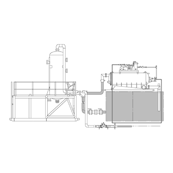
90‐90‐885 (Rev. B) Section 2 MAIN DATA 2‐1 FUNCTIONAL DESCRIPTION The M‐I SWACO Total Gas Containment (TOGA) System is designed to contain, separate and remove the free and entrained gases from the drilling fluid circulated from the well bore. Total containment and removal of the gases from the fluid is accomplished through a unique combination of M‐I SWACO’s MUD/GAS SEPARATOR* and High Vacuum D‐GASSER*. The gas is removed from the drilling fluid and vented into a closed flare system and burned at a safe distance, to prevent any toxic or combustible gas from escaping around the rig floor or mud pit area. TOGA* 2‐1 ... - Page 8 90‐90‐885 (Rev. B) THIS PAGE INTENTIONALLY LEFT BLANK 2‐2 TOGA* ...
-
Page 9: Technical Description
90‐90‐885 (Rev. B) Section 3 TECHNICAL DESCRIPTION 3‐1 PRINCIPLES OR THEORY OF OPERATION The drilling fluid circulated from a well may include gas and/or formation liquids which have entered the well bore. As the fluid approaches the surface the hydrostatic pressure is reduced, and the gas bubbles in the fluid expand and form heads or massive pockets of gas. These heads of gas or gas cut mud are circulated from the well bore through the flow line or choke manifold into a six inch inlet line on the MUD/GAS SEPARATOR*. The free gas is separated from the fluid by a series of baffles in the vessel and vented into the flare line through an eight inch line on the top of the MUD/GAS SEPARATOR* Vessel. 3‐1.1 MUD/GAS SEPARATOR* Float Valve The Float operated control valve inside the MUD/GAS SEPARATOR* vessel opens to prevent overfilling of the Vessel and closes to maintain a liquid seal on the eight inch Mud Return Line. The liquid seal prevents the separated gas from being discharged into the mud return line. 3‐1.2 Back Pressure Manifold The Back Pressure Manifold is installed in the MUD/GAS SEPARATOR* Vent Line to dampen the surge effects from the expanding gas and prevent the blowing of mud into the Vent Line. A back pressure setting of 15‐50 psi (1.1 – 3.5 kg/cm squared) is recommended on the MUD/GAS SEPARATOR* Vessel. 3‐1.3 D‐GASSER* The gas cut mud discharged from the MUD/GAS SEPARATOR* is drawn into the D‐GASSER* Vessel by a vacuum force created by the discharge pipe low pressure jet assembly. The fluid is distributed over a baffle in a thin evenly dispersed layer. This thin layer of fluid is exposed to a vacuum of at least eight inches of mercury created by the vacuum pump. The vacuum force removes the entrained gases from the fluid and the degassed fluid is discharged into the active system. The entrained gas removed from the fluid by the D‐GASSER* is vented into the closed flare system, down‐stream of the MUD/GAS SEPARATOR* Back Pressure Manifold. The TOGA* system utilizes M‐I SWACO’s standard MUD/GAS SEPARATOR* and D‐GASSER* which have been specifically modified to assure total containment and control of the toxic gas cut mud. The modified D‐GASSER* includes two complete vacuum pump systems. The vacuum pump exhaust lines are connected through a manifold containing a series of check valves to prevent the possibility of blow back from the flare lines. Plug valves located on either side of the check valves are used to provide a means to isolate and safely repair or replace either vacuum pump system while the other is still operational as well as to configure the vacuum pump systems for alternative methods of operation. The first alternative is to run both vacuum pump systems simultaneously to assure maximum degassing efficiency when large volumes of gas are encountered. The second alternative is to provide a means for redundancy in the event the primary vacuum pump system fails during kick conditions. TOGA* 3‐1 ... - Page 10 90‐90‐885 (Rev. B) 3‐1.3 D‐GASSER* Continued Another modification to the D‐GASSER* is the 3‐way float controlled valve to preserve the TOGA* System integrity of totally containing the gas from the well. The 3‐way float controlled valve is connected to the exhaust side of the vacuum pumps to prevent atmospheric air from entering the vessel when the valve opens to break the vacuum while controlling the fluid level in the vessel. The gas entering the vessel through the 3‐way valve is simply recycled gas coming from the vacuum pumps. 3‐1.4 Back Flow Manifold A tee located on the MUD/GAS SEPARATOR* mud return line connects the suction line of the D‐GASSER* and the mud line from the active system with the discharge of the MUD/GAS SEPARATOR*. The mud line to the active system maintains a constant flow of fluid to the D‐GASSER* when low flow conditions from the MUD/GAS SEPARATOR* exist. The mud line from the active system has a check valve assembly to assure that gas cut mud discharged by the MUD/GAS SEPARATOR* will not by pass the D‐GASSER* and enter the active system. 3‐2 TOGA* ...
-
Page 11: Preparation
90‐90‐885 (Rev. B) Section 4 PREPARATION 4‐1 PREPARATION OF EQUIPMENT FOR INSTALLATION It is advisable to make a pre installation inspection of the rig site to assure proper installation. The relative positions of the D‐GASSER* and MUD/GAS SEPARATOR* are extremely important to assure correct operation and efficiency of the TOGA* system. The MUD/GAS SEPARATOR* mud return line should be a minimum of four feet (1.2 m) below the D‐GASSER* suction. The MUD/GAS SEPARATOR* mud return line should also be even with the highest fluid level expected in the mud tank. This orientation of the MUD/GAS SEPARATOR* will maintain a constant flow of fluid to the D‐GASSER* when low flow rates from the MUD/GAS SEPARATOR* are encountered. 4‐1.1 Erecting The Land Version MUD/GAS SEPARATOR* (Figure 4‐1) Before being placed in position, the MUD/GAS SEPARATOR* should be erected in an area which allows for a winch truck or crane to work at the end and side of the skid. First install all railing sections securely in place on the top of the skid. To erect the MUD/GAS SEPARATOR*, position the winch truck/crane at the end of the skid where the bottom of the vessel is positioned. The A‐frame on the winch truck should be high enough to raise the lifting eye (1) attached to the top of the vessel 11 feet (3.4 m) above the skid. Open the expanded metal flooring (2) and connect the winch line to the lifting eye (1) on the vessel. Raise the vessel past the vertical position, and place the support beam (3) under the free edge of the vessel and lower the vessel onto the beam. Close the flooring grates and place the support beams under them as required. The MUD/GAS SEPARATOR* is now ready for placement. Lifting eyes (4) are provided at each end of the skid. When the MUD/GAS SEPARATOR* is placed in the desired position, check to be sure the bottom of the skid is level and the MUD/GAS SEPARATOR* vessel is in a vertical position. To obtain different height adjustments of the MUD/GAS SEPARATOR* remove the pins (5) locking the upper and lower leg sections of the skid. Raise the entire upper section of the skid by the lifting eyes (4) to the required height, and re‐insert the locking pins in each leg. 4‐1.2 Securing The Offshore MUD/GAS SEPARATOR* Before raising the MUD/GAS SEPARATOR*, check that the four bolts securing the vessel to the stand are in place and tightened. Any lifting device being used should be high enough to raise the lifting eye attached to the top of the vessel 18 feet (5.5 m) above the rig floor. Connect the lifting device to the lifting eye on the vessel. Raise the vessel to the vertical position, and align the stand‐to‐rig mounting holes. Secure the stand to the rig floor then remove metal shipping brace from the vessel. TOGA* 4‐1 ... -
Page 12: Equipment Installation
90‐90‐885 (Rev. B) 4‐1.1 Erecting The Land Version MUD/GAS SEPARATOR* Continued Figure 4‐1. Erecting The MUD/GAS SEPARATOR* 4‐1.3 D‐GASSER* Inspection The D‐GASSER* and accessory equipment should be inspected for shipping damage. Manipulate all controls and moving parts to determine whether they are mechanically operable. If the inspection reveals no damage the unit is ready for installation. 4‐2 EQUIPMENT INSTALLATION (SEE FIGURE 7‐1 OR FIGURE 7‐2) 4‐2.1 Choke Manifold Lines And Blowout Preventer Bypass Lines The customer will provide the six inch lines from the choke manifold and BOP bypass to the MUD/GAS SEPARATOR*. These lines should be as straight as the rig layout permits. If turns are necessary, they should be made using a tee. The tee end opposite the inlet should be capped using a plug filled with an abrasion resistant material such as pewter. 4‐2.2 Mud Return Line Before connecting the mud return line to the D‐GASSER* suction line, check to see that the eight inch butterfly valve (fluid seal level controller) (Figure 7‐3, Item 26 or Figure 7‐4, Item 22) is positioned so it will close when the operating lever is raised. If the valve does not close it may have been installed backwards or rotated to place the operating lever on the opposite side. Be certain the butterfly valve is operating correctly before continuing with the installation procedure of the mud return line. 4‐2 TOGA* ... - Page 13 PRESSURE BUILDS UP TO PUSH THE LIQUID THROUGH THE LINE.. THIS PRESSURE INCREASE MAY CAUSE THE LINE TO POUND SEVERELY RESULTING IN DAMAGE TO EQUIPMENT AND POSSIBLE INJURY TO PERSONNEL. The first section of gas vent line extends from the top of the MUD/GAS SEPARATOR* vessel to a point near the eight inch mud discharge valve. An eight inch swing pipe is provided to compensate for the vessel height when raising the adjustable skid. This swing pipe is connected to the inlet of the back pressure manifold using a Victaulic coupling. The gas vent line should be assembled where it will not allow fluid to accumulate in the line. The exhaust from the dual vacuum pumps on the D‐GASSER* should be connected to the flare line down‐stream of the back pressure regulator assembly. TOGA* 4‐3 ...
- Page 14 90‐90‐885 (Rev. B) 4‐2.4 D‐GASSER* The D‐GASSER* should be installed on or near the mud pit with the bottom of the skid not to exceed 3 feet above the normal operating mud level. Suction and discharge pipes should be kept as short as possible. For best results, the bottom of the suction line should be at least 4 inches (10.2 cm) above the bottom of the tank, at least 3 feet (0.9 m) below the operating mud level, and 12 inches (30.5 cm) or more away from the side of the tank. The discharge assembly should be at least 3 feet (0.9 m) long and should extend below the mud pitʹs minimum operating mud level. In order to return the excess volume of mud that is normally handled by the D‐GASSER* to the first pit, an equalizer line should be provided to permit the mud to flow between the two pits while the equipment is operating at a high level. On initial installations, it may be necessary to adjust the turnbuckle that is attached to the 3‐way valve so that the stem of the valve extends 3/8 inch (0.95 cm) out the bottom of the valve body, when the ball is completely down, resting on the bottom of the trough inside the vacuum vessel. 4‐2.5 D‐GASSER* Vacuum And Fluid Control NOTE: THE FLOAT LEVEL SHOULD BE VISUALLY SET BEFORE THE DISCHARGE PIPING IS CONNECTED TO THE D‐GASSER*. The customer will furnish piping necessary to connect the vacuum pump outlet manifold to the flare line downstream of the back pressure valve assembly. A modified 3‐way valve is used on the D‐GASSER*. The bottom of the 3‐way valve is connected downstream of the back pressure regulator assembly and uses vented gas to break the vacuum, thereby controlling the fluid level in the vessel while maintaining vent gas containment. The turnbuckle connected to the float adjusts the fluid level in the vessel by setting the valve to break the vacuum at a specific float level. 4‐2.5.1 Mud Jet The D‐GASSER* uses a low pressure jet fed by an external, customer furnished centrifugal pump and use a 1‐1/2 inch nozzle. Jet volume and pressure requirements for various D‐GASSER* throughput volumes and mud weights may be determined from the performance data found in Table 4‐2 and Figure 4‐3. 4‐4 TOGA* ...
- Page 15 90‐90‐885 (Rev. B) Figure 4‐2. Suggested Locations Of D‐GASSER* TOGA* 4‐5 ...
- Page 16 EXERCISE EXTREME CAUTION WHEN WORKING WITH ELECTRICAL CIRCUITRY, ESPECIALLY WHEN STARTER ENCLOSURES AND MOTORS HAVE THEIR COVERS REMOVED FOR CURRENT AND VOLTAGE TESTS. BEFORE MAKING ANY ELECTRICAL CONNECTIONS, MAKE SURE THE POWER SOURCE IS DISCONNECTED AND THE STARTER IS IN THE OFF POSITION. A 3 horsepower motor is used to drive each vacuum pump. An explosion proof manual starter is supplied with each vacuum pump assembly and is pre‐wired at the factory. After it has been verified that the motor and starter are wired for the proper voltage, the electrical power source can be connected to the starters. Table 4‐1 is provided as an aid when connecting the motors to the power source. After connecting the power source, momentarily start each motor to make certain the vacuum pump rotates in the same direction as indicated by the arrow located on one of the vacuum pump sheave spokes. The rotation of any 3 phase motor can be reversed by changing any two wires in the starter box. 4‐6 TOGA* ...
- Page 17 90‐90‐885 (Rev. B) Table 4‐1. Motor Wiring WARNING! ALWAYS disconnect power before attempting ANY maintenance or repair work. 1‐ to line 1* 2‐ to line 2* 380 V‐AC 3‐ to line 3* 50 Hz 4‐7 3 Phase 8‐5 9‐6 * To change rotation, change any two wires on line. TYPICAL WIRING DIAGRAM (50 & 60 Hz) LOW VOLTAGE MOTOR WIRING DIAGRAM HIGH VOLTAGE MOTOR WIRING DIAGRAM TOGA* 4‐7 ...
-
Page 18: D-Gasser* Capacity -Vs- Centrifugal Pump Output
22 515 1950 25 10ʺ 600 2270 29 660 2500 33 11ʺ 700 2650 38 760 2880 44 12ʺ 770 2910 44 875 3310 57 13ʺ 875 3310 59 950 3600 70 * Horsepower shown is calculated for 10 lb/gal (1.2 kg/liter) mud. D‐GASSER* volume will be reduced slightly and the horsepower increased proportionally if abnormal friction (such as long mud line loss) is incurred between the pump and the jet. 4‐8 TOGA* ... - Page 19 90‐90‐885 (Rev. B) 4‐3 D‐GASSER* CAPACITY ‐VS‐ CENTRIFUGAL PUMP OUTPUT CONTINUED D‐GASSER* performance curves are illustrated in the figure below. If conditions arise where additional volumes are required, contacted the M‐I SWACO technical services engineering department. Figure 4‐3. Jet Pressure to Flow Rate Curves TOGA* 4‐9 ...
- Page 20 90‐90‐885 (Rev. B) THIS PAGE INTENTIONALLY LEFT BLANK 4‐10 TOGA* ...
Need help?
Do you have a question about the TOGA and is the answer not in the manual?
Questions and answers