Subscribe to Our Youtube Channel
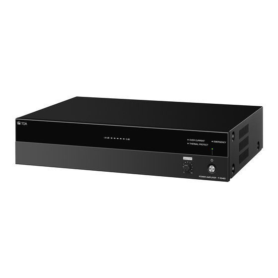
Summary of Contents for Toa P-3548D
- Page 1 INSTRUCTION MANUAL POWER AMPLIFIER P-3548D Thank you for purchasing TOA’s Power Amplifier. Please carefully follow the instructions in this manual to ensure long, trouble-free use of your equipment.
-
Page 2: Table Of Contents
TABLE OF CONTENTS 1. SAFETY PRECAUTIONS ................3 2. GENERAL DESCRIPTION ................5 3. FEATURES ......................5 4. INSTALLATION PRECAUTIONS ............. 5 5. NOMENCLATURE AND FUNCTIONS ..........6 Front ..........................6 Rear ..........................7 6. CONNECTIONS ....................8 6.1. Speaker Connection ..................... 8 6.2. -
Page 3: Safety Precautions
AC outlet and personal injury. contact your nearest TOA dealer. Make no further attempt to operate the unit in this condition as this When Installing the Unit may cause fire or electric shock. - Page 4 • Contact your TOA dealer as to the cleaning. If dust is • Be sure to follow the instructions below when rack- allowed to accumulate in the unit over a long period mounting the unit.
-
Page 5: General Description
A-3600D series Mixer amplifier (option). It employs a PFC circuit. The P-3548D can also be used as a stand-alone amplifier. 3. FEATURES • Two parallel inputs, one is speaker line input (–10 dB/0 dB), the other is line input. -
Page 6: Nomenclature And Functions
5. NOMENCLATURE AND FUNCTIONS [Front] 1. Power switch 4. Thermal protection indicator (Red) Press this switch to turn on the power. To turn off Lights while the internal protection circuit is the power, press this switch again. operating. Note Operation of the power switch is disabled while 5. -
Page 7: Rear
[Rear] 17 18 8. AC inlet 11. Impedance setting switch Connect the supplied power cord to this receptacle. Changes the speaker output impedance either to low or high. CAUTION 100 V: High impedance 4 – 16 Ω: Low impedance Notes Be sure to use the supplied power cord. -
Page 8: Connections
6.1. Speaker Connection For cable wiring to the removable terminal block, refer to p. 12. Notes P-3548D • Never make connection to both 4 – 16 Ω (low impedance) and 100 V line (high impedance) terminals simultaneously. • Never make connection to 4 – 16 Ω terminal when the Impedance setting switch is set to 100 V. -
Page 9: Speaker Line Input Connection
Nominal position mark [Volume adjustment] First, set the Speaker line input volume control at the nominal position mark. P-3548D Then, adjust the volume with the Master volume control on the front panel while monitoring the sound being broadcast from the speakers. -
Page 10: Remote Power On/Off Control Connection
For cable wiring to the removable terminal block, refer to p. 12. 6.4.1. Remote power control input terminal connection With the P-3548D’s power turned OFF, it can be remotely turned ON from the optional A-3500D series or A-3600D series Mixer amplifier by making the Remote IN-OUT terminal connections as shown below. -
Page 11: Emergency Input And Control Input Terminal Connections
Emergency input signals to go through bypassing the master volume control. Opening the Emergency control input terminals automatically returns the muted signals to the original level. A-3600D series A-3500D series The figure represents the A-3500D series. P-3548D P-3548D... -
Page 12: Removable Terminal Plug Connection
6.6. Removable Terminal Plug Connection Step 1. Wiring the supplied removable terminal plug. [Recommended type of screwdriver ] 1-1. Loosen the terminal screws to insert the wire. 1-2. Tighten the terminal screws. Blade width* Ensure that the wire does not break free when pulled. -
Page 13: Installing To An Equipment Rack
Plastic foot When installing the unit to an equipment rack, remove the four plastic feet screwed on the unit’s base as shown below. P-3548D When installing the unit to an equipment rack, use the optional MB-25B Rack mounting bracket. CAUTION Rack-mounting screws are not supplied with the optional MB-25B Rack mounting bracket. -
Page 14: Block Diagram
9. BLOCK DIAGRAM... -
Page 15: Specifications
10. SPECIFICATIONS Power Source 220 – 240 V AC, 50/60 Hz Rated Output 480 W Power/Current 601 W (rated output), 113 W (based on EN62368), Consumption 200 mA or less (when power switch is OFF) Frequency Response 50 Hz – 20 kHz ±3 dB (1/8 rated output) Distortion 1% or less at 1 kHz, rated power (20 kHz LPF (AUX-0025)) Signal to Noise Ratio... - Page 16 URL: https://www.toa.jp/ 133-02-00601-00...


Need help?
Do you have a question about the P-3548D and is the answer not in the manual?
Questions and answers