
Subscribe to Our Youtube Channel
Related Manuals for YOKOGAWA DTSXL


Summary of Contents for YOKOGAWA DTSXL
- Page 1 User’s DTSXL Manual Distributed Temperature Sensor Long Range System Guide IM 39J06B40-01EN IM 39J06B40-01EN 14th Edition...
- Page 2 Blank Page...
-
Page 3: Introduction
This user’s manual (IM 39J06B40-01EN) describes the overview, operation, and maintenance of the DTSXL Distributed Temperature Sensor Long Range System (DTSXL System). This manual is written for all those who will be using the DTSXL System. Before using the DTSXL System, read this document and “Read Me First”... -
Page 4: Safety Precautions
• If any protection or safety circuit is required for the system controlled by the product or for the product itself, prepare it separately. • Be sure to use the spare parts approved by Yokogawa Electric Corporation (hereafter simply referred to as YOKOGAWA) when replacing parts or consumables. - Page 5 Warning and Disclaimer The product is provided on an “as is” basis. YOKOGAWA shall have neither liability nor responsibility to any person or entity with respect to any direct or indirect loss or damage arising from using the product or any defect of the product that YOKOGAWA cannot predict in advance.
- Page 6 < Safety Precautions > Symbol Marks Throughout this manual, you will find several different types of symbols being used to identify different sections of text. This section describes these icons. WARNING Identifies instructions that must be observed in order to avoid physical injury and electric shock or death of the operator.
- Page 7 System (for SMF)” in the case of specification of DTSXL for single mode fiber. To be compliant with these standards, the DTSXL System hardware needs to be installed in a lockable metal cabinet. Applicable when CPU module NFCP050 is used.
- Page 8 < Safety Precautions > *12: “X” indicates specific condition of use, in a hazardous area of Zone 2, install DTSXL System in a lockable metal cabinet which meets the IP54 or higher protection rating provided in IEC 60529. *13: The EAC mark is as follows.
- Page 9 < Safety Precautions > ● Installation Be careful not to drop and damage the equipment during installation to avoid equipment damage or injury. WARNING ● Wiring Power Cable Connect the power cables according to the procedure given in this document. The power cables must conform to the safety standards of the country where the device is installed.
- Page 10 < Safety Precautions > ● Battery • Yokogawa designated batteries must be used. • Mount and change batteries following the procedure given in this document. WARNING SEE ALSO For more information about batteries, refer to C4.3.1 “Batteries for DTSX3000”.
- Page 11 < Safety Precautions > ● Laser Beam Safety Precautions for Laser Products This instrument uses a laser light source. This instrument is a Class 1M laser product as defined by IEC 60825-1:2007 Safety of Laser Products—Part1: Equipment classification and requirements, and a Class1 laser product as defined by IEC 60825-1:2014 Safety of Laser Products—Part1: Equipment classification and requirements.
- Page 12 < Safety Precautions > Invisible laser light is output from the OPTICAL OUTPUT terminal located on the front face of this instrument. When Optical switch module connects to DTSX3000 with the optical fiber, the laser beam is output from optical terminals of Optical switch module. WARNING Do not look directly or indirectly into the laser beam or at a specular reflection of the beam without protective equipment.
- Page 13 Beware especially in high temperature installation environments. Measurement Before performing distributed temperature measurement: Ensure that the environment complies with the DTSXL System specifications, and Perform temperature calibration of the sensor optical fiber with DTSXL System. Drawing Conventions Some drawings may be partially emphasized, simplified, or omitted, for the convenience of description.
-
Page 14: Copyright And Trademark Notices
PC network or the like), or registered or recorded on video tapes. Trademark and License Software Acknowledgments • DTSX and FAST/TOOLS are registered trademarks of Yokogawa Electric Corporation. • STARDOM and CENTUM are trademarks of Yokogawa Electric Corporation. - Page 15 xiii < Copyright and Trademark Notices > Blank Page IM 39J06B40-01EN 14th Edition: May 30, 2022...
-
Page 16: Table Of Contents
A3. Power Supply Equipment ............A-16 A3.1. Power Supply System ............... A-16 A3.2. Supplied Power Source ..............A-16 A3.3. Grounding for DTSXL System ............A-18 A4. Installation and Attachment ............A-19 A4.1. Installing the Base Module ..............A-19 A4.2. Installing Other Modules onto the Base Module ......A-21 A4.3. - Page 17 A6.1. Choosing Sensor optical fiber ............A-56 A6.2. Precautions When Choosing Sensor optical fiber ......A-56 PART - B Software..........B-i B1. Before Using the DTSXL System ..........B-1 B1.1. Functional Overview of the DTSX3000 ..........B-1 B1.2. Functions ..................... B-2 B1.3.
- Page 18 A-xvi B5.1.2. RS232 Connection ..............B-22 B5.2. Ethernet Communications ..............B-22 B5.2.1. Login Function ................ B-22 B5.2.2. HTTP and HTTPS ..............B-23 B5.2.3. SFTP/SCP ................B-23 B5.2.4. SSH ..................B-23 B5.2.5. Modbus/TCP................B-24 B6. System Configuration ..............B-25 B6.1. Overview .................... B-25 B6.1.1.
- Page 19 A-xvii B7.1. Overview .................... B-75 B7.2. Measurement Sequence ..............B-75 B7.2.1. Sequence Table Settings ............B-75 B7.2.2. Sequence Control ..............B-77 B7.3. Channel Settings ................B-82 B7.3.1. Fiber Settings ................. B-84 B7.3.2. Double-ended Measurement Settings ........B-88 B7.3.3. Calibration ................B-90 B7.4.
- Page 20 C4. Hardware Maintenance .............. C-15 C4.1. Periodic Inspection ................C-15 C4.2. Maintenance and Replacement Operations ........C-16 C4.2.1. Precautions for Operation ............C-16 C4.2.2. Replacing DTSXL System Modules ......... C-17 C4.3. Parts with Limited Lifespan .............. C-19 IM 39J06B40-01EN 14th Edition: May 30, 2022...
- Page 21 A-xix C4.3.1. Batteries for DTSX3000 ............C-19 C4.3.2. Power Supply Module ............. C-26 C4.3.3. Replacing Other Parts ............. C-26 C4.4. Sensor Optical Fiber ................C-29 C4.5. Fault Isolation and Self Diagnosis ............ C-30 C4.5.1. Self-diagnosis ................. C-31 C4.5.2. Fault Isolation ................. C-32 IM 39J06B40-01EN 14th Edition: May 30, 2022...
- Page 22 DTSXL Distributed Temperature Sensor Long Range System PART – A Hardware IM 39J06B40-01EN PART - A Hardware This chapter describes the hardware overview of theDTSXL Distributed Temperature Sensor Long Range System (DTSXL System). IM 39J06B40-01EN 14th Edition: May 30, 2022...
- Page 23 Blank Page IM 39J06B40-01EN 14th Edition: May 30, 2022...
-
Page 24: A1. Dtsxl System
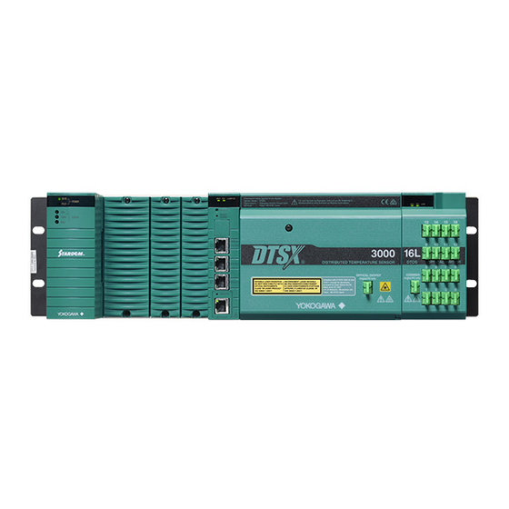
CPU module, DTSX3000 Distributed Temperature Sensor, and Optical Switch modules are installed) DTSX3000 Distributed Temperature Sensor (Main module of the DTSXL Distributed Temperature Sensor Long Range System with built-in communication functions) Optical Switch module (module with built-in optical switch required for channel... - Page 25 DTSX3000 Distributed Temperature Sensor Optical Switch module Power Supply module CPU module Dummy cover Figure Configuration Examples for DTSXL System Appearance 482.6 Unit: mm Figure Appearance of DTSXL System Modules Mounted on 19-inch Rack IM 39J06B40-01EN 14th Edition: May 30, 2022...
-
Page 26: A1.2. Dtsx3000 Distributed Temperature Sensor
SERIAL 3 of RS-232C is dedicated for maintenance use. A repeater hub cannot connect. *11: Dimensions exclude protective cap of optical connector. *12: Refer to GS 39J06Z40-01EN in the case of specification of DTSXL for single mode fiber. IM 39J06B40-01EN 14th Edition: May 30, 2022... - Page 27 < PART – A Hardware > Appearance ● Front View Mounting screw Operation status LEDs LEDs (from left to right) HRDY, RDY, LASER ON Reset Switch Shutdown Switch Serial Port 3 Serial Port 2 Serial Port 1 LEDs (from top to bottom) Network power switch Network interface LEDs (from top to bottom)
- Page 28 < PART – A Hardware > Pin Assignment, LEDs, and Switches ● Pin Assignment Table Pin Assignment of Serial Port (RS-232) RJ45 RS-232 Signal Name Conversion to D-sub Connector Pin No. D-sub 9pin Male D-sub 9pin Female (Straight Cable) (Crossover Cable) DCD (Data Carrier Detect) DSR (Data Set Ready)
- Page 29 < PART – A Hardware > ● Switches Table Various Switches Name Purpose Reset Switch Press this switch to reboot the DTSX3000. Shutdown Switch Press this switch to terminate the DTSX3000 safely. Network power switch Press this switch when not using network functions. IM 39J06B40-01EN 14th Edition: May 30, 2022...
-
Page 30: A1.3. Optical Switch Module
Dimensions exclude protective cap of optical connector. Refer to GS 39J06Z40-01EN in the case of specification of DTSXL for single mode fiber. Note: As a guideline, the module should be replaced periodically every 4.7. 6 and 9.5 years for continuous operation of 15- second, 20-second and 30-second measurements, respectively. - Page 31 < PART – A Hardware > Appearance ● Front View Operation status LED (LEDs from left: HRDY、RDY、ALARM) Operation status LED Operation status LED Channel display LED Channel display LED Channel display LED Optical input Optical input Optical input Optical output Optical output Optical output DTOS2L...
- Page 32 < PART – A Hardware > ● LED Table Status Indicators LED Indicator Color Description HRDY Green Lit when the hardware is operating normally. Green Lit when the system is operating normally. ALARM Green Flashes when an alarm condition is present. Active Channel Green Indicates an active channel.
-
Page 33: A1.4. Base Module
A-10 < PART – A Hardware > A1.4. BASE MODULE The DTSX3000 base module, which is also compatible with the DTSXL200, is used for mounting various function modules including the DTSX3000 Distributed Temperature Sensor, power supply modules, optical switch modules and CPU module. IMPORTANT Dummy covers must be installed on all empty slots of the base module. -
Page 34: A1.5. Rack Mount Kit
A-11 < PART – A Hardware > A1.5. RACK MOUNT KIT The rack mount kit can be used for laying optical fibers in a cabinet. Specification Table Specifications of Rack Mount Kit (DTRK10) Item Specifications Dimensions (W x H x D) 482.6×235×43.6 mm Weight 0.87 kg... -
Page 35: A1.6. Optical Fiber For Dtsx
A-12 < PART – A Hardware > A1.6. OPTICAL FIBER FOR DTSX The optical fiber for DTSX is used for checking the operation of the DTSX3000. Optical fiber is 50/125μm GI. It is not available for Distributed Temperature Sensor for Single Mode Fiber and Optical Switch Module for Single Mode fiber. -
Page 36: A1.7. Power Supply Module
A-13 < PART – A Hardware > A1.7. POWER SUPPLY MODULE One of the following power supply modules must be selected when configuring a DTSXL system. Dual-redundant configuration is not allowed for the power supply module. Table Power Supply Modules Compatible with DTSXL System... -
Page 37: A2. Installation Environment
Cooling Natural air cooling Not applicable to DTFB10. Refer to GS 39J06Z40-01EN “DTSXL Distributed Temperature Sensor Long Range System (for SMF)” in the case of specification of DTSXL for single mode fiber. 0 to +55 °C when power supply module NFPW441, NFPW442, or NFPW444 is used. - Page 38 - For vibration at the installation location, see also “DTSXL System Vibration Criteria” within this Chapter. - For radio device noise to DTSXL System, see “Radio Device Noise to DTSXL System” within this Chapter. Vibration Criteria of DTSXL System Ensure that if the frequency of vibration at the installation location is 58 Hz or less, the total amplitude is kept below 0.15 mm.
-
Page 39: A3. Power Supply Equipment
IMPORTANT To conform the power supply system for the DTSXL System to safety standards, use a breaker or a switch that conforms to the safety standards. A3.2. Supplied Power Source The following items must be considered to ensure stable DTSXL System operation. - Page 40 A-17 < PART – A Hardware > A: Ideal input voltage wave with no distortion B: Distorted input voltage wave Figure Distortion of Input Voltage Waveform Inrush Current An input current much larger than normal will flow when the power supply is turned on. Refer to the specification of the power supply module for inrush currents to each power supply module.
-
Page 41: A3.3. Grounding For Dtsxl System
To prevent such risks, install an uninterrupted power supply (UPS) device. A3.3. Grounding for DTSXL System When DTSXL System is installed in a cabinet (with a 19-inch rack), instrument panel, or the like, it is functionally insulated by the insulation bushings (accessories of DTSBM10). -
Page 42: A4. Installation And Attachment
Do not expose the unit to direct sunlight All access to the DTSXL System is from the front. Reserve a space of 100 and 150 mm from the front panel of the unit to the cabinet door to provide enough space for the cables. - Page 43 A-20 < PART – A Hardware > Installing to a 1 9-Inch Rack When installing the base module to a 19-inch rack or general-purpose control panel, install the supplied insulation bushings to insulate the base module from the rack as shown in the diagram.
-
Page 44: A4.2. Installing Other Modules Onto The Base Module
Installation Position of Each Module This section describes the positioning of the modules for installation to the base module. Slot numbers Figure Installation Positions of DTSXL System Modules Table Installation Positions of DTSXL System Modules Module Installation Position... - Page 45 A-22 < PART – A Hardware > Installing Modules The procedures for installing a module to and removing a module from the base module are described below. Screws Screws Figure Example for Attaching a DTSX3000 to the Base Module ●...
-
Page 46: A4.3. Considerations On Environment Inside Cabinet Or Panel
Cabinet or Panel Arrangement When determining the internal arrangement of the cabinet or panel in which the DTSXL System is to be installed, ensure that operability and maintainability will not be compromised and take the following environmental concerns into consideration. - Page 47 Provide adequate ventilation to release heat to the outside. Avoid installing a high heat-producing device right below DTSXL System. Cool down the DTSXL System with forced ventilation or a cooler when the temperature beneath the module is above 65 °C (55°C when NFPW441, NFPW442, or NFPW 444 is used).
- Page 48 Vibration and Shock Considerations Keep external vibration and shock to the DTSXL System within specified limits by insulating the cabinet or panel from vibration and shock generating sources or fixing the cabinet or panel with rubber isolators.
-
Page 49: A4.4. Noise Considerations
A4.4. Noise Considerations Isolation from Power and Motor-circuit Cables Lay any power or motor-circuit cable at least 20 cm away from the DTSXL system and all signal cables connected to the DTSXL system. Should this be impossible, run the power or motor-circuit cables all the way through a metal conduit that is grounding (100 Ω... - Page 50 A-27 < PART – A Hardware > Communication Signals Communication signal wires carry high-speed signals. Lay these wires in a separate duct at least 10 cm away from other input/output wires. IMPORTANT Be sure to use specified cables and take extra special care with grounding and cable/wire runs.
-
Page 51: A4.5. Corrosive-Gas Environment Compatibility
A-28 < PART – A Hardware > A4.5. Corrosive-gas Environment Compatibility The DTSXL System employs modules which meet the ANSI/ISA G3 optional environment requirements and are compatible with the corrosive gas-susceptible environment. SEE ALSO Refer to the general specifications (GS 39J06B40-01EN) of each module to check whether each module meets the G3 environment requirements. - Page 52 A-29 < PART – A Hardware > Table Corrosive-gas Environment Classification Severity Level Mild Moderate Harsh Severe Copper corrosion level ≥2000 [Å] <300 <1000 <2000 (<0.03) (<0.1) (<0.2) (≥0.2) ([μm]) Group A ≥50 <3 <10 <50 , SO ≥300 <10 <100 <300 ≥10...
-
Page 53: A4.6. Fm Nonincendive
A4.6. FM Nonincendive A4.6.1. Precaution for Nonincendive The DTSXL System have been approved that the products meet the Nonincendive (NI) (*1) requirements of the FM Standards. By this approval, these devices can be installed in Class I Division 2 (*2) hazardous locations, but for compliance with the standard, the devices must be installed in a cabinet approved by local explosion-proof testing organization. - Page 54 A-31 < PART – A Hardware > NI Products and Their Configuration The figure below shows the example, how to configure NI products for DTSXL System installed in Class I Division 2 Hazardous Locations. SEE ALSO For NI products for DTSXL System, see the table below.
- Page 55 LIVE UNLESS AREA IS KNOWN TO BE NON-HAZARDOUS. Cabinet for DTSXL System DTSXL System must be installed in a lockable metal cabinet with a key. Use a cabinet approved by the authority having jurisdiction. Use the DTSXL System accommodated in the cabinet on condition that the ambient temperature of the DTSXL System meets its specifications, considering temperature rise in the cabinet.
-
Page 56: A4.6.2. Nfm031-A11
A-33 < PART – A Hardware > A4.6.2. NFM031-A11 The contents of NFM031-A11 are shown below. IM 39J06B40-01EN 14th Edition: May 30, 2022... -
Page 57: A4.7. Atex Type "N
- Explosive atmospheres-Part15: Equipment protection by type of protection “n” The DTSXL System is indoor use. It can be installed in a hazardous location of Zone 2 after accommodating them in a keyed cabinet (*1) of protection rating IP54 or higher. It is possible to directly connect a node unit installed in a non-hazardous location and a Type “n”... - Page 58 The figure below is an example of the configuration of Type “n” approved products that can be installed in hazardous locations. SEE ALSO For Type “n” approved DTSXL System, see the table below. <Non-Hazardous Location> <Hazardous Location Zone 2> Lockable Metal Cabinet (IP54)
- Page 59 EN61010. Power Cable The power cables of DTSXL System must be passed through a metal conduit, and wired from a nonhazardous location without applying stress to the end of the cables. In addition, connect cables according to local electrical codes for explosion-proof.
- Page 60 QU’IL NE S’AGISSE D’UN EMPLACEMENT NON DANGEREUX. Cabinet for DTSXL System DTSXL System must be installed in a lockable metal cabinet with a key. Use a cabinet approved by local explosion-proof testing organization. Use the DTSXL System accommodated in the cabinet on condition that the ambient temperature of the DTSXL System meets its specifications, considering temperature rise in the cabinet.
-
Page 61: A4.8. Csa Non-Incendive
CSA Standards. A4.8.1. CSA Non-incendive DTSXL System have been approved that the products meet the Non-incendive (NI) (*1) requirements of the CSA Standards. By this approval, these devices can be installed in Class I Division 2 (*2) hazardous locations, but for compliance with the standard, the devices must be installed in a cabinet approved by local explosion-proof testing organization. - Page 62 A-39 < PART – A Hardware > NI Products and Their Configuration The figure below shows the example, how to configure NI products for DTSXL System installed in Class I Division 2 Hazardous Locations. SEE ALSO For NI products for DTSXL System, see the table below.
- Page 63 < PART – A Hardware > Power Cable The power cables of DTSXL System must be passed through a metal conduit, and wired from a nonhazardous location without applying stress to the end of the cables. In addition, connect cables according to the Canadian Electrical Code (CEC) or local electrical codes.
- Page 64 QU’IL NE S’AGISSE D’UN EMPLACEMENT NON DANGEREUX. Cabinet for DTSXL System DTSXL System must be installed in a lockable metal cabinet with a key. Use a cabinet approved by the authority having jurisdiction. Use the DTSXL System accommodated in the cabinet on condition that the ambient temperature of the DTSXL System meets its specifications, considering temperature rise in the cabinet.
-
Page 65: A5. Wiring
A-42 < PART – A Hardware > A5. Wiring IMPORTANT Do not bend or press the power cable or the signal cable if the ambient temperature is minus 20 degrees Celsius or below. Cables with the temperature rating of an ambient temperature plus 10 °C or more must be used. - Page 66 A-43 < PART – A Hardware > Table Example of Ring Tongue Terminal Specification Conductor nominal Screw Hole Outer Terminal Insulation cross-sectional area used diameter terminal length sleeve internal (mm) (mm) diameter (mm) diameter (mm) (mm) 0.5 to 1.65 Approx. (AWG 20 to 16) or more or less...
- Page 67 A-44 < PART – A Hardware > CAUTION When using power supply module NFPW426, you must also connect the power supply to the analog field power supply terminal as shown in the figure below. (Beware that this part of the connection differs from the description given in the manual of the power supply module.) If this connection is not done, the power capacity of the NFPW426 may be exceeded and the power supply cut off.
-
Page 68: A5.2. Wiring The Ground
Grounding resistance must be 100 Ω or less. CAUTION Ground only the specified, dedicated grounding terminal. DTSXL System needs to be grounded to prevent electric shocks and effects of foreign noise. grounding resistance must be 100 Ω or less. Applicable Cables Insulated cables for industrial equipment such as;... -
Page 69: A5.3. Connecting The Signal Cable
A-46 < PART – A Hardware > A5.3. Connecting the Signal Cable Communication Cables The signal cable can be connected in the following ways: Network Connect the network cable to the connector in the front of the DTSX3000. Use cables that comply with the 100BASE-TX standard. This precaution relates to control network cable connection. - Page 70 A-47 < PART – A Hardware > IMPORTANT When not using the network interface, leave the connector cover for dust protection on to prevent any damage to the connector. SEE ALSO When using and performing wiring for the CPU module NFCP050, you should also refer to the STARDOM FCN/FCJ Guide (IM 34P02Q01-01E), installation guide (TI 34P02Q91-01E) and technical guide (TI 34P02A03-01E).
-
Page 71: A5.4. Routing And Connecting A Sensor Optical Fiber
A-48 < PART – A Hardware > A5.4. Routing and Connecting a Sensor Optical Fiber A5.4.1. Measurement You can configure the DTSX3000 to perform single-ended measurement or double- ended measurement. In double-ended measurement, the sensor optical fiber needs to be looped back, which halves its effective measurement distance. However, it is an effective measure against unknown sensor optical fiber loss or sensor optical fiber darkening. -
Page 72: A5.4.2. Routing Sensor Optical Fibers
It will be easier to connect a sensor optical fiber to the DTSX3000 if about one turn of extra cable length is provided near the DTSX3000. If the DTSXL System is to be installed in a cabinet, provide adequate space within the cabinet for routing the sensor optical fiber. More space is needed for routing additional sensor optical fibers if the optical switch module is used with the DTSXL System in the cabinet. -
Page 73: A5.4.3. Connecting A Sensor Optical Fiber
A-50 < PART – A Hardware > As the DTSXL System is to be installed vertically on a wall, sensor optical fibers must be supported. The DTRK10 rack mount kit (option) is recommended for this purpose. The DTRK10 rack mount kit is designed to support sensor optical fibers and cords which are no more than 3 mm in diameter. - Page 74 A-51 < PART – A Hardware > SEE ALSO The following optical fiber and optical connector are recommended for use with the DTSX3000. - Refer to GS39J06B40-01EN Ensure that the end face of the optical connector is free of dirt or scratches. If visual inspection is inadequate, we recommended using an observation microscope to check the end face of the optical connector.
- Page 75 A-52 < PART – A Hardware > Optical connector Lever Optical connector DTSX3000’s optical connector The connector must be inserted perpendicularly. a) Angled view b) Side view Figure B Mating the Connectors Figure C Properly Mated Check the connected optical fiber and ensure that neither its optical connector nor optical fiber is subjected to stress.
-
Page 76: A5.4.4. Disconnecting A Sensor Optical Fiber
A-53 < PART – A Hardware > A5.4.4. Disconnecting a Sensor optical fiber Follow the procedure below to disconnect the optical connector of a sensor optical fiber from the optical output connector of the DTSX3000 Disconnection Procedure: 1. Stop the operation of the DTSX3000. Always ensure that no measurement is in progress before disconnecting a sensor optical fiber. -
Page 77: A5.4.5. Connecting An Optical Switch Module To The Dtsx3000 With
A-54 < PART – A Hardware > A5.4.5. Connecting an Optical Switch Module to the DTSX3000 with the optical fiber When an optical switch module is used with the DTSX3000, the optical fiber provided with the optical switch module must be connected between them. The optical fiber must be connected directly between the optical connector for optical output on the DTSX3000 and the optical connector for optical input on the optical switch module. - Page 78 A-55 < PART – A Hardware > CAUTION Handling precautions for optical fibers: Use optical connectors and optical fibers that meet product specification requirements. Connecting the wrong type of optical connector to the DTSX3000 may damage not only the optical connector but also the optical connector of the DTSX3000 or the optical switch module.
-
Page 79: A6. Sensor Optical Fiber
A-56 < PART – A Hardware > A6. Sensor Optical Fiber A6.1. Choosing Sensor optical fiber Sensor optical fibers to be used must satisfy the DTSXL System specifications. Table Sensor Optical Fiber Specifications Item Specification Requirements Optical connector E2000/APC 50/125 µm GI quartz fiber or SM fiber... - Page 80 Pay special attention to the bending radius and the stress of a sensor optical fiber at its exit from the optical connector which is connected to the DTSXL System. If the DTSXL System is installed in a cabinet, ensure that the cabinet door does not touch the optical fibers when the door is closed.
- Page 81 A-58 < PART – A Hardware > ● Temperature calibration The DTSX3000 must be temperature-calibrated with the sensor optical fiber connected. Temperature calibration must be done when the DTSX3000 is first used or when optical fiber is replaced. Moreover, re-calibration is required if optical fiber characteristics change due to aging or other reasons.
- Page 82 DTSXL Distributed Temperature Sensor Long Range System PART – B Software PART - B Software IM 39J06B40-01EN IM 39J06B40-01EN 14th Edition: May 30, 2022...
- Page 83 Blank Page IM 39J06B40-01EN 14th Edition: May 30, 2022...
-
Page 84: Part - B Software
B1. Before Using the DTSXL System B1.1. Functional Overview of the DTSX3000 The DTSX3000 of the DTSXL System measures the temperature distribution over the length of an optical fiber using the fiber itself as the sensing element. The module can be combined with appropriate power supply and optical switch modules to configure a required system. -
Page 85: B1.2. Functions
< PART – B Software > B1.2. Functions DISTRIBUTED TEMPERATURE SENSOR (DTSX3000) ● Software Functions Item Function Controls channel switching by optical switch DTOS2L, Optical switch control (*1) DTOS4L or DTOS16L. Measurement control Starts measurement and stops measurement Settings for channel combination, measurement (Global) measurement sequence, measurement mode (single-ended or double- settings... - Page 86 < PART – B Software > (Continued) Item Function Firmware upgrade, power management, reset Maintenance functions processing, time setting and maintenance functions SSH, SFTP, SCP and HTTPS; authentication using Authentication functions username and password Up to 10 users can be registered for use with HTTPS User registration functions server and SSH server.
- Page 87 < PART – B Software > ● Network Function ( Ethernet ) Ethernet is used for connecting the DTSX3000 to the DTSX3000 Control Visualization Software (DTAP3000), the DTSX3000 Data Conversion Software (DTAP3000D), autonomous controllers FCN/FCJ and various types of PLCs. It is also used for maintenance of the DTSX3000.
- Page 88 < PART – B Software > ● Time Synchronization Function The DTSX3000 supports time synchronization between SNTP (Simple Network Time Protocol) enabled devices. The DTSX3000 can run as an SNTP client. Item Client Functions SNTP (Simple Network Time Protocol) Communications protocol UDP port: 123 Unicast mode (*1) Available...
-
Page 89: B1.3. Connection
For risks arising from connecting the DTSX3000 with external networks such as the Internet or the like, please go to the URL below. However, the information on the following website does not cover all the possible risks. https://partner.yokogawa.com/global/member/ofs/index.htm B1.3.1. Connecting to Control Devices The DTSX3000 can be connected to STARDOM, CENTUM and other control devices and be controlled via Modbus Communication (Modbus/TCP and Modbus Serial). -
Page 90: B1.3.2. Connecting To Various Software For Dtsx3000
We recommend using the latest versions of software for DTSX3000. Beware that some DTSX3000 functions may be unavailable if an older version is used. About latest version of DTAP3000 DTSX3000 Control Visualization Software, contact your Yokogawa sales representative or local distributor. -
Page 91: B1.4. Ip Address Configuration
< PART – B Software > SEE ALSO For details on how to use the DTSX3000 Control Visualization Software (DTAP3000) and Data Conversion Software, read their respective user manuals. - DTAP3000 DTSX3000 Control Visualization Software Guide (IM 39J02B40-01EN) - DTAP3000D Data Conversion Software WITSML1.3.1.1 Guide (IM 39J02B40-03EN) The Web browser and software for DTSX3000 can be installed and used on the same PC. - Page 92 < PART – B Software > The IP Address Configuration Tool runs on Windows. It needs to be installed on the PC first by running the installer program provided on the accompanying CD-ROM following the procedure below: 1. Insert the accompanying CD-ROM into the CD-ROM drive of the PC to be installed with the IP Address Configuration Tool.
- Page 93 B-10 < PART – B Software > Confirm to begin installation. If you have accepted the terms of the license, the installation initiation window is displayed. Click the [Install] button to begin installation. Installation begins. When installation completes, the installation completion window is displayed.
- Page 94 B-11 < PART – B Software > Connect the DTSX3000 and PC using an Ethernet cable. Perform connection as described below. The PC installed with the IP Address Configuration Tool runs as a DHCP server to assign IP addresses to DTSX3000 units. To avoid problems arising from having two DHCP servers running on the same network, connect the PC and the DTSX3000 one-to-one.
- Page 95 B-12 < PART – B Software > Run the IP Address Configuration Tool. Double-click on the DTSX IP Address Config Tool icon on Windows desktop. The IP Address Configuration Tool runs. Configure IP addresses using the following procedure. IM 39J06B40-01EN 14th Edition: May 30, 2022...
- Page 96 B-13 < PART – B Software > Define the MAC address and IP address mapping table. Map the MAC address of a DTSX3000 to the IP address to be assigned to the DTSX3000 by selecting the Enable checkbox at the beginning of the row. IP address settings for up to ten DTSX3000 units can be saved.
- Page 97 B-14 < PART – B Software > Terminate the IP Address Configuration Tool. Click the [Stop] button to terminate the execution of the IP Address Configuration Tool. Perform system configuration After IP Address configuration is completed, the DTSX3000 boots up in maintenance mode.
-
Page 98: B1.5. System Configuration
On the displayed user authentication dialog, enter a valid user name and password. The following user is pre-registered in the factory. Username: dtsx Password: YOKOGAWA User authority: Administrator (admin) After user authentication succeeds, the top maintenance window is displayed. IM 39J06B40-01EN... - Page 99 B-16 < PART – B Software > Perform user registration, time, network and other required configuration according to Chapter B6, “System Configuration.” - We recommend changing the default password of the pre-registered “dtsx” user right away. - To connect to the DTSX3000 using the DTSX3000 Control Visualization Software (DTAP3000) or the DTSX3000 Data Conversion Software WITSML1.3.1.1(DTAP3000D), which are available as separate purchases, the user must have ReadWrite authority.
-
Page 100: B2. Using The Dtsx3000
B-17 < PART – B Software > B2. Using the DTSX3000 B2.1. Operation Flowchart The operation flowchart below shows the overall operation flow when using the DTSX3000 for the first time. For details on individual items, see the respective chapters or sections indicated in the flowchart. -
Page 101: B3. Starting And Stopping The System
B-18 < PART – B Software > B3. Starting and Stopping the System B3.1. Starting the System Start the system by switching on its power supply. You can also start the system by pressing the [RESET] switch when it is in ready-for-power-down state (shutdown state). B3.2. -
Page 102: B4. System Operation
B-19 < PART – B Software > B4. System Operation B4.1. Operation Overview The figure below shows transitions between the various DTSX3000 operation states. The current operation state of the DTSX3000 can be determined by checking the states of its LED indicators. Figure DTSX3000 Operation States IM 39J06B40-01EN 14th Edition: May 30, 2022... -
Page 103: B4.2. Boot Mode Selection State
B-20 < PART – B Software > B4.2. Boot Mode Selection State The boot mode can be selected when the DTSX3000 is in Boot mode Selection state. The following three boot mode options are available. The boot mode currently selected is indicated by the states of the LED indicators. -
Page 104: B4.8. Shutdown State
The DTSX3000 enters Test mode automatically if the system software is not installed or a fatal error is detected during system boot. Contact your Yokogawa service representative if your DTSX3000 is in Test mode. B4.10. SD Card Error State The DTSX3000 enters SD Card Error state if it detects an error during SD card installation check. -
Page 105: B5. Communication Functions
B-22 < PART – B Software > B5. Communication Functions The DTSX3000 is equipped with Ethernet and serial communication ports, which can be used for external communications. B5.1. Serial Communication The DTSX3000 has three serial communication ports, namely COM1, COM2 and COM3, which can be used for Modbus communications, as well as maintenance communications. -
Page 106: B5.2.2. Http And Https
B-23 < PART – B Software > B5.2.2. HTTP and HTTPS Web Service The web service enables system information and RAS information to be displayed, as well as the system operation mode and system configuration data of the DTSX3000 to be modified using any Web browser running on a PC. -
Page 107: B5.2.5. Modbus/Tcp
B-24 < PART – B Software > SEE ALSO The SSH function can be enabled or disabled in the system configuration using a Web browser running on a PC. For details on how to do so, see Subsection B6.4.7, “SSH & SFTP Configuration (SSH & SFTP)”... -
Page 108: B6. System Configuration
B-25 < PART – B Software > B6. System Configuration B6.1. Overview To customize the operation of the DTSX3000, you need to correctly specify DTSX3000 system configuration data to match the application environment. System configuration data of the DTSX3000 can be modified and displayed using any Web browser running on a Windows PC. - Page 109 B-26 < PART – B Software > To modify system configuration data, you need to access the DTSX web page using a user ID with Administrator authority. If user authentication is successful, the Top page is displayed. IM 39J06B40-01EN 14th Edition: May 30, 2022...
-
Page 110: B6.1.2. Top Page
B-27 < PART – B Software > B6.1.2. Top Page The figure below shows a sample top page. The top page consists mainly of the state/authority display area, the side menu, the display/configuration area and the auxiliary information display area. The state/authority display area displays the operation state of the DTSX3000 and the operation authority (privilege) of the user accessing the DTSX3000 from a Web browser. -
Page 111: B6.1.3. Operation States And Operation Authority
B-28 < PART – B Software > B6.1.3. Operation States and Operation Authority The DTSX3000 can run in two operation states, namely online state and maintenance state. In online state, you can display and view almost all DTSX3000 configuration data from a Web browser even during measurement execution. - Page 112 B-29 < PART – B Software > The current operation state is displayed in the state/authority display area. Examples of the state/authority display in various states are shown in the figures below. Online state Online state Maintenance state (No authority granted) Maintenance state (no authority granted) [Acquire Auth] button...
- Page 113 B-30 < PART – B Software > Revup authority granted Revup authority granted Button for releasing Revup authority Revup authority not granted Revup authority not granted Message indicating that Revup authority is not granted because another user has Revup authority. IM 39J06B40-01EN 14th Edition: May 30, 2022...
-
Page 114: B6.1.4. How To Transit Between Operation States
B-31 < PART – B Software > B6.1.4. How to Transit between Operation States This subsection describes how to transit between operation states and how to acquire authority. Procedure for transiting from online state to maintenance state 1. Click [Reboot] in the side menu. Click Reboot. - Page 115 B-32 < PART – B Software > 2. The Reboot page is displayed. Select the Reboot (Maintenance Mode) option and click the [OK] button. Select Reboot (Maintenance Mode) Click the [OK] button. 3. When the confirmation window is displayed, click the [OK] button. Click the [OK] button.
- Page 116 B-33 < PART – B Software > 5. After reboot After reboot has completed, access the DTSX3000 from the Web browser and verify that the operation state has changed to maintenance state with no authority granted. Maintenance state (no authority granted) Do not reboot the DTSX3000 during temperature measurement.
- Page 117 B-34 < PART – B Software > Procedure for acquiring operation authority in Maintenance (no authority granted) state 1. Click the [acquire auth] button. Maintenance state (no authority granted) Click the [acquire auth] button. 2. Confirm that operation authority has been granted. Maintenance state (Operation authority granted) Click Date.
- Page 118 B-35 < PART – B Software > If no other user has been granted operation authority, the configuration modification window is displayed. As an example, click Date after operation authority is granted Maintenance state (operation authority granted) Date modification window If another user has acquired authority, the DTSX3000 transits to Maintenance (no authority granted) state without displaying the configuration modification window.
- Page 119 B-36 < PART – B Software > Procedure for acquiring and releasing Revup authority in maintenance state 1. Click the [Lock] button to acquire Revup authority. Maintenance state (operation authority granted) Button for locking Revup authority 2. Confirm that Revup authority has been granted. To release Revup authority, click the [Unlock] button.
-
Page 120: B6.1.5. Auxiliary Information Display
B-37 < PART – B Software > B6.1.5. Auxiliary Information Display The figures below show some examples of auxiliary information displayed in the auxiliary information display area Alarm display An alarm icon is displayed when any message at or above the configured log alarm level described in Subsection B6.4.16, “Log Alarm Level Configuration (Log Alarms)“... - Page 121 B-38 < PART – B Software > Error messages Error messages (such as a message informing that a specified value is out of the valid data range) are displayed. Error message IM 39J06B40-01EN 14th Edition: May 30, 2022...
-
Page 122: B6.2. Item List
B-39 < PART – B Software > B6.2. Item List The table below lists the system configuration items. Side Menu Item Function Description Sys Maintenance Maintenance information Displays maintenance information. Informations RAS Information display Display RAS information. Sys log System log display Display system log messages. -
Page 123: B6.3. Configurable Items In Each Operation State
B-40 < PART – B Software > B6.3. Configurable Items in Each Operation State The table below shows the configuration items available for display and configuration in various operation states. Menu Item Online State Maintenance State Normal Operation Revup/Restore Authority Authority granted authority... -
Page 124: B6.4. System Configuration And Display Items
Buttons for switching display among ras0 to ras9 information. RAS information is used by Yokogawa for system analysis, and at times may need to be saved and sent to Yokogawa for fault diagnosis in the event of a system failure. SEE ALSO For details on saving RAS information, see Subsection B6.4.15, “Save Log (Saveinfo).”... -
Page 125: B6.4.2. Log Display (Sys Log And App Log
B-42 < PART – B Software > B6.4.2. Log Display (Sys log and App log) You can lists messages logged by the system (system log) and messages logged by applications (application log) in log display by selecting Sys log or App log from the side menu. -
Page 126: B6.4.3. User Management (User
B-43 < PART – B Software > B6.4.3. User Management (User) You can add, delete or change the password of a DTSX3000 user in user management. List of registered users Change password. Add a user. Select a user type from: ・Admin ・User-ReadOnly ・User-ReadWrite... - Page 127 B-44 < PART – B Software > Changing User Password Select [User Password Change]. - Name Select the user whose password is to be changed from the displayed list. - New Password Specify a new password. A password must begin with an alphanumeric character, and consist of alphanumeric characters and any of the "! # $ &...
- Page 128 B-45 < PART – B Software > - The “dtsx” user cannot be deleted. - Deleting a user does not remove the user’s home directory. - You cannot delete the “root” user. IM 39J06B40-01EN 14th Edition: May 30, 2022...
-
Page 129: B6.4.4. Network Configuration (Network
B-46 < PART – B Software > B6.4.4. Network Configuration (Network) You can specify the hostname, IP address and domain name of the DTSX3000, as well as other network-related settings in network configuration Hostname, IP address, subnet mask and default gateway settings for the DTSX3000 Domain name settings IP address settings for DNS... - Page 130 B-47 < PART – B Software > - Host Name Optionally specify a hostname for the DTSX3000. A hostname must begin and end with an alphanumeric character, consist only of alphanumeric characters, the period (.) character and the hyphen (-) character, and be no longer than 32 characters. - IP Address Specify an IP address, which must consist of only numeric characters and the period (.) character, and be no longer than 15 characters.
-
Page 131: B6.4.5. Date And Time Configuration (Date
B-48 < PART – B Software > B6.4.5. Date and Time Configuration (Date) You can specify the internal clock date, time and time zone for the DTSX3000 in date and time configuration by selecting Date from the side menu. Next, select the checkboxes for the settings to be configured and specify the required settings. - Page 132 B-49 < PART – B Software > Specify a date from 01/01/2001 to 12/31/2037. Specify a time from 00:00:00 to 23:59:59. Display input helper window Please select Settngs with selected checkboxes If settings are correct, click the [OK] button. IM 39J06B40-01EN 14th Edition: May 30, 2022...
- Page 133 B-50 < PART – B Software > Time zone can be entered directly or specified using the timezone setting helper window. How to do so is described on the following pages. Select a date from the calendar. You can use the two left and right arrows at the top to switch the display to the desired month.
- Page 134 B-51 < PART – B Software > Jn:the number of days from 1st January, which is considered day 1. J is a prefix n is an integer from 1 to 365 (2/29 is not included in the calculation so 2/28 and 3/1 are to be specified as J59 and J60 respectively) n:the number of days from 1st January, which is considered day 0.
- Page 135 B-52 < PART – B Software > Specifying time zone with the time zone setting helper window (using Date setting method) Select [date] for the [Setting method]. After specifying the required settings, press the [Convert] button. A time zone string is converted automatically from the specified settings. Select the date setting method.
- Page 136 B-53 < PART – B Software > Specifying time zone with the time zone setting helper window (using the Week setting method) Select [week] for the [Setting method]. After specifying the required settings, press the [Convert] button. Select the Week setting method. Convert the information specified above to a timezone string.
- Page 137 B-54 < PART – B Software > A time zone string is converted automatically from the specified settings. Converted timezone string. Copy converted string to Timezone field in Date window. IM 39J06B40-01EN 14th Edition: May 30, 2022...
-
Page 138: B6.4.6. Web Server Configuration (Web
B-55 < PART – B Software > B6.4.6. Web Server Configuration (Web) You can specify DTSX3000 Web server authentication related items in Web server configuration. Authentication enable. Maintenance settings. HTTPS enable. Save the above settings to DTSX3000. Initialize to factory settings. - Digest Authentication Specify whether to enable or disable user authentication. - Page 139 B-56 < PART – B Software > ● Enabling HTTPS Put the DTSX3000 into maintenance state. Transfer the SSL server certificate file to the DTSX3000 using SFTP or some other means. Log on to the DTSX3000 as a user with Admin authority. Execute the following command to store the SSL server certificate file.
-
Page 140: B6.4.7. Ssh & Sftp Configuration (Ssh & Sftp
B-57 < PART – B Software > B6.4.7. SSH & SFTP Configuration (SSH & SFTP) You can enable or disable the SSH, TELNET and FTP server functions in SSH & SFTP Configuration. Save the above settings to DTSX3000. Initialize to factory settings. If using SSH, select yes;... -
Page 141: B6.4.8. Serial Port Configuration (Serial
B-58 < PART – B Software > B6.4.8. Serial Port Configuration (Serial) You can select the serial port (COM1 and COM2) of the DTSX3000 to be assigned for the PPP function and Modbus serial function, as well as define communication settings in serial port configuration. -
Page 142: B6.4.9. Ppp Server Configuration (Ppp
B-59 < PART – B Software > B6.4.9. PPP Server Configuration (PPP) This configuration item is intended for maintenance use and is normally not used. Set PPP Enable to no. Select no. IM 39J06B40-01EN 14th Edition: May 30, 2022... -
Page 143: B6.4.10. Ntp Server Configuration (Ntp
B-60 < PART – B Software > B6.4.10. NTP Server Configuration (NTP) You can specify whether to perform clock time synchronization with NTP servers on the network, as well as specify the hostnames or IP addresses of the NTP servers in NTP server configuration. -
Page 144: B6.4.11. Led Power Save Configuration (Led
B-61 < PART – B Software > B6.4.11. LED Power Save Configuration (LED) You can disable or enable the LED power save mode, which reduces the LED brightness to 33 %, in LED Power Save Configuration. Save the above setting to DTSX3000. -
Page 145: B6.4.13. System Configuration Restoration (Restore
B-62 < PART – B Software > B6.4.13. System Configuration Restoration (Restore) By selecting Restore from the side menu, you can restore DTSX3000 system configuration data from a configuration archive file saved previously on a PC using system configuration backup. Press the [Browse] button. -
Page 146: B6.4.14. System Revision Update (Revup
B-63 < PART – B Software > B6.4.14. System Revision Update (Revup) You can perform revision update of the DTSX3000 kernel, root file system and DTSX3000 applications in system revision update by selecting Revup from the side menu. SEE ALSO See Section B11.6, “System Revision Update”... -
Page 147: B6.4.16. Log Alarm Level Configuration (Log Alarms
B-64 < PART – B Software > B6.4.16. Log Alarm Level Configuration (Log Alarms) You can specify a log level for reporting alarms for the system log, as well as the application log, in log alarm level configuration by selecting Log Alarms from the side menu. -
Page 148: B6.4.17. Reboot/Shutdown (Reboot
B-65 < PART – B Software > B6.4.17. Reboot/Shutdown (Reboot) You can reboot or shutdown the DTSX3000, as well as select the boot mode (operation state of the DTSX3000 after reboot) in reboot/shutdown by selecting Reboot from the side menu. Boot up in online mode. -
Page 149: B6.5. Application Configuration Items
B-66 < PART – B Software > B6.5. Application Configuration Items B6.5.1. Power Save Settings Using power save settings, you can configure the power save function, which suspends power supply to measurement hardware when no measurement is being done. When power save is enabled, the system behaves as follows: - After power on, the system goes into wait state for a start measurement instruction. -
Page 150: B6.5.2. Modbus Related Settings
B-67 < PART – B Software > - Power Save Select whether to enable or disable power save. Select yes to enable power save and no to disable power save. The default value is no. B6.5.2. Modbus Related Settings Modbus related Settings include Modbus TCP related Settings and Modbus Serial related Settings. -
Page 151: B6.5.3. Data Conversion Related Settings (Data Convert
B-68 < PART – B Software > - Slave Address Specify the address number to be used. Available port numbers are from 1 to 247. Default value is 1. - Protocol Select either RTU or ASCII for the protocol to be used. Select “rtu” if using RTU and select “ascii”... - Page 152 B-69 < PART – B Software > IMPORTANT If you change the converted file format, previously stored converted files will be deleted on the next reboot. Therefore, you should back up any required converted files using the procedure for retrieving measurement data.
- Page 153 B-70 < PART – B Software > - Delete files Select the files to be deleted. Select [All files] to delete all files; select [Transferred file] to delete transferred files. Check the [Delete files] selection, and then click the [Set] button. The following confirmation window is displayed.
-
Page 154: B6.5.4. Cv Software Related Settings
B-71 < PART – B Software > B6.5.4. CV Software Related Settings CV Software related settings can be used to configure communications between the DTSX3000 and the DTSX3000 Control Visualization Software as follows: - Allow or disallow connection with the DTSX3000 Control Visualization Software - Port number for DTSX3000 - Communication timeout duration - Make port number public or non-public... -
Page 155: B6.6. List Of Error Messages
B-72 < PART – B Software > B6.6. List of Error Messages The following tables lists and describes the messages displayed in the auxiliary information display area. ● Top Page Message Description Loading of system log or application log has failed. Error: can not read "Log alarm level". - Page 156 B-73 < PART – B Software > ● Date and time configuration window Message Description Error: Not date format The format of the specified date is invalid. Error: Illegal date The numeric value specified for year, month or date is invalid. Error: Not time format The format of the specified time is invalid.
- Page 157 B-74 < PART – B Software > ● CV software related settings window Message Description Error : Port number that can be used are The specified port number must be from 1024 to 65535. from 1024 to 65535 Error : Timeout that can be used are 5 to The specified timeout value must be from 5 to 1800.
-
Page 158: B7. Temperature Measurement
B-75 < PART – B Software > B7. Temperature Measurement B7.1. Overview The DTSX3000 supports both single-ended and double-ended distributed temperature measurement. In single-ended measurement, a light pulse is launched from one end of the sensor optical fiber and the returned Raman scatter is measured to determine temperature distribution. - Page 159 B-76 < PART – B Software > Up to 16 entries (the limit depends on whether an optical switch is installed and the number of installed channels) can be configured in the sequence table as described below. - Use Select the checkbox of a table entry to enable it. - Principle Select [Single End] for single-ended measurement or [Double End] for double- ended measurement.
-
Page 160: B7.2.2. Sequence Control
B-77 < PART – B Software > ・ Interval Specify a value from 0 [s] to 3600 [s] in units of 1 [s]. The preceding sample screen capture defines the following sequence: Ch1 measurement → wait until 60 seconds after beginning of Ch1 measurement → Ch2 measurement →... - Page 161 B-78 < PART – B Software > Sequence Mode Specify sequence Single Repetition Mode interval. Continuous Sequence Interval Start Time Setting Sequence Start Time Every Day Specify up to 6 values One Cycle in Start Time Table. IM 39J06B40-01EN 14th Edition: May 30, 2022...
- Page 162 B-79 < PART – B Software > - Sequence Mode If [Single] is selected, the sequence defined in Subsection B7.2.1, “Sequence Table Settings” is executed once, after which measurement stops. If [Continuous] is selected, the sequence defined in sequence table settings is executed repeatedly until a stop measurement command is received.
- Page 163 B-80 < PART – B Software > In the example shown above (where [Start Time Setting] is 1 Cycle), the measurement sequence is executed thrice at 00:00, 07:00 and 14:00 hours respectively, after which the system goes into idle mode. 07:00 14:00 00:00...
- Page 164 B-81 < PART – B Software > In the example shown above, the measurement sequence is executed every day at 01:00 hours. Day 2 Day 3 Day 1 01:00 hours 01:00 hours 01:00 hours [sec] 3rd sequence 2nd sequence 1st sequence execution execution execution...
-
Page 165: B7.3. Channel Settings
B-82 < PART – B Software > B7.3. Channel Settings You can configure parameters related to measurement time and measurement accuracy for each channel using channel settings. Only settings for the channel specified as Channel(Near) as described in Subsection B7.2.1, “Sequence Table Settings”... - Page 166 B-83 < PART – B Software > SEE ALSO For details on the System Configuration window, see Chapter B6, “System Configuration.” - Sampling Resolution Select either 1 m or 2 m for the sampling resolution. The maximum allowable sampling size is 30000. Accordingly, the specified distance range divided by the specified sampling resolution must not exceed 30,000.
-
Page 167: B7.3.1. Fiber Settings
B-84 < PART – B Software > - Masking When a fiber failure is detected, it masks temperature in the range where temperature cannot be measured due to fiber failure. : does not mask. 999 degC : masks temperature to +999 degC. -273 degC : masks temperature to -273 degC. - Page 168 B-85 < PART – B Software > Specify 0.0 [m] if no optical switch is installed. - Well Inlet Position Specify the well inlet position relative to the DTSX3000 exit position as a value from 0.0 [m] to 50000.0 [m] in units of 0.1 [m]. This parameter is used when distance values are converted to depth values for an axis.
- Page 169 B-86 < PART – B Software > Basic Parameters Up to 20 sensor optical fibers can be connected. Basic Parameters can be specified for each of the fibers to be connected. - Length Specify the sensor optical fiber length of a fiber section as a value from 0.0 [m] to 50000.0 [m] in units of 0.1 [m].
- Page 170 B-87 < PART – B Software > - For double-ended measurement, the Loss setting need not be specified because the measurement results of the forward and reverse directions are combined. Even if specified, it will not affect the temperature calculation result. However, the Loss setting is required when a fiber failure is detected.
-
Page 171: B7.3.2. Double-Ended Measurement Settings
B-88 < PART – B Software > B7.3.2. Double-ended Measurement Settings As measurement results of the forward and reverse directions are combined in double- ended measurement, loss correction is not required. However, absolute temperatures must still be corrected for the total differential loss between the Stokes and anti-Stokes light over the full fiber length. - Page 172 B-89 < PART – B Software > Using the execution result of differential loss measurement Select [Measurement] and specify the following parameters for differential loss measurement. ● Specifying the Near End - Distance Of W To P1 Specify the near end P1 (by its distance from the switch exit position W) as a value from 0.0 [m] to 50000.0 [m] in units of 0.1 [m].
-
Page 173: B7.3.3. Calibration
B-90 < PART – B Software > B7.3.3. Calibration Calibration must be done to achieve accurate temperature measurement by setting calibration parameters in the DTSX3000 beforehand. Calibration To perform temperature calibration, select [Use], and then specify the following parameters. - Calibration Type Select the calibration type from Manual Input, Remote Input and Optical Switch. - Page 174 B-91 < PART – B Software > SEE ALSO For details on how the wavenumber is calculated, see Chapter C2. Correction The correction function performs correction of DTSX3000 measured temperature using linear correction coefficients. We do not recommend using this correction function of the DTSX3000;...
-
Page 175: B7.4. Executing Measurement
B-92 < PART – B Software > B7.4. Executing Measurement B7.4.1. Executing Measurement and Checking Status After specifying the above settings, you can start measurement. You can also check created measurement data, reported errors and other statuses during measurement. SEE ALSO For details on remote commands for executing measurement and checking statuses, see the DTSX3000 Communications (Modbus) Manual. -
Page 176: B8. Measurement Data Output
B-93 < PART – B Software > B8. Measurement Data Output B8.1. Overview of Data Output The DTSX3000 converts measured data into LAS (Log ASCII Standard version 2.0) formatted or CSV formatted files and stores them in its non-volatile internal memory area. -
Page 177: B8.1.1. Las Files
B-94 < PART – B Software > B8.1.1. LAS Files The mapping between configuration items and output items in LAS files is described in this subsection. Configuration Items Well information and data output conditions can be configured. Well information specifies locality and other information about the well to be measured, as well as the output format of measurement start date and time in LAS files. - Page 178 B-95 < PART – B Software > LAS File Format The figure below shows a sample LAS file. Any text following a pound (#) character or a colon (:) character on a line is comment text. Message Description Version info section Information about the LAS format version.
-
Page 179: B8.1.2. Csv Files
B-96 < PART – B Software > The number of data values contained in the data section varies with the Calculation Range setting. SEE ALSO For details on the calculation range, see Subsection B7.3.1, "Fiber Settings." B8.1.2. CSV Files The mapping between configuration items and output items in CSV files is described in this subsection. - Page 180 B-97 < PART – B Software > SEE ALSO For details on the measurement start time, see Subsection B8.2.3, "Format of Measurement Start Time.” CSV File Format The figure below shows a sample CSV file. Company,Company A <- item 1 Well,Well A <- item 2 Field,Field A...
-
Page 181: B8.1.3. Format Of Measurement Start Time
B-98 < PART – B Software > B8.1.3. Format of Measurement Start Time The measurement start time can be formatted automatically using format specifiers. Either UTC or local time representation can be selected. In addition, arbitrary text can be specified within the date format string. The following format specifiers, if specified in the date format string, are automatically converted by DTSX3000 into its associated data as shown in the table below. -
Page 182: B8.2. Executing Data Output
B-99 < PART – B Software > B8.2. Executing Data Output After defining the output conditions, you can start measurement. You can also check created measurement data, reported errors and other statuses during measurement. SEE ALSO For details on remote commands for executing measurement and checking statuses, see the "DTSX3000 Communications Guide (IM39J06B40-02EN)". -
Page 183: B8.3.2. File Name Structure
B-100 < PART – B Software > B8.3.2. File Name Structure You can include file creation year, month and day, as well as measured channel number as part of generated file names using format specifiers. The final file name consists of a user specified part and an auto-assigned part. The former is a result of format conversion according to specified format specifiers while the latter is assigned automatically by DTSX3000. - Page 184 B-101 < PART – B Software > Auto-assigned part The auto-assigned part, which includes internal control information, is generated automatically by DTSX3000. The following character strings are assigned in the auto-assigned part. Item Data Description Represents the file format type. 00 = LAS format File type 01 = WITSML format...
-
Page 185: B8.3.3. Archive Directory
B-102 < PART – B Software > B8.3.3. Archive Directory Converted files in LAS and other formats are archived in the /mnt/data/BACKUP directory. Two levels of subdirectories are created below the BACKUP directory, with files stored in subdirectories at the lowest level. The subdirectory names at the two levels match the mm and nn numbers included in the auto-assigned part of the file name of a file stored thereunder. -
Page 186: B8.4. Retrieving Measurement Data
B-103 < PART – B Software > B8.4. Retrieving Measurement Data This section describes how to get files using SFTP client software and how to transfer files to an external HTTP server using the HTTP Client function of the DTSX3000. The described procedures are not guaranteed to work in all application environments. - Page 187 B-104 < PART – B Software > - If the number of existing connections to the DTSX3000 is already the maximum allowed, the DTSX3000 rejects the login request from the SSH/SFTP, the client receives the following message and connection fails. Received message too long 1416589088 - If this message is displayed, check the number of existing connections, disconnect any existing connection no longer required and then try connecting to the DTSX3000 again.
- Page 188 B-105 < PART – B Software > 2. Move to the desired folder. Change the current local directory and the current remote directory. Current remote directory (/mnt/data/BACKUP/mm/nn on DTSX3000) Current local directory (any folder on the PC) Get files. Select one or more files to be retrieved from the remote directory side, and then drag and drop it into the local directory side.
- Page 189 B-106 < PART – B Software > When retrieval is completed, the filenames are displayed in the local directory side. If a file having the same name already exists in the local directory side before transfer, a confirmation dialog is displayed. By clicking [No to All], you can shorten transfer time by retrieving only files that are not already present.
- Page 190 B-107 < PART – B Software > Select [Synchronize] from the menu bar. Select [Synchronize] Get files. Specify the Synchronization options as shown in the dialog below, and press the [OK] button. Transfer from DTSX3000 to a local Select file existence as the only synchronization condition.
- Page 191 B-108 < PART – B Software > Repeat steps 2 and 3 to perform resynchronization. During DTSX3000 measurement, new files are added constantly to the /mnt/data/LATEST directory. Repeat steps (2) and (3) to perform resynchronization. Only files newly added to the /mnt/data/LATEST directory will be retrieved to the local directory.
-
Page 192: B8.4.2. Http Client Function
B-109 < PART – B Software > B8.4.2. HTTP Client Function Converted data files can be transmitted to an external HTTP server using the HTTP client function of DTSX3000. Specifications The table below describes the specifications of the HTTP client function of the DTSX3000. - Page 193 B-110 < PART – B Software > Deflate Select whether to transmit compressed gzip files or uncompressed plain text files. If one of the following occurs when Since Selection is set to Transmit Files, DTSX3000 can’t start to convert measured data into LAS formatted files and can’t start to transmit the files. Please reselect another transmission file at the restart.
- Page 194 B-111 < PART – B Software > Next, we describe below the transmission settings for two examples, one using PUT method and the other using POST method, for the same sample configuration on the HTTP server side. This description assumes that the HTTP server uses Apache2.2.3 (CentOS).
- Page 195 B-112 < PART – B Software > ● Transmission settings Specify a URI, user ID and password appropriate for the desired destination directory. Specify a URI Destination directory on HTTP server side https://<hostname or IP address>/webdav /var/www/html/webdav https://<hostname or IP address>/webdav_basic /var/www/html/webdav/basic https://<hostname or IP address>/webdav_digest /var/www/html/webdav/digest...
- Page 196 B-113 < PART – B Software > Example using POST method In this example for transmitting files from DTSX3000 to a HTTP server using the POST method, we show a sample configuration on the HTTP server side, sample CGI programs for communicating with the HTTP client function of DTSX3000 and sample transmission settings on the DTSX3000.
- Page 197 B-114 < PART – B Software > ● CGI programs user authentication is not required Form data name * Specify this in server & transmit file settings Destination directory for storing received files. IM 39J06B40-01EN 14th Edition: May 30, 2022...
- Page 198 B-115 < PART – B Software > for Basic authentication The file content is the same as upload.cgi shown above except for the $path value shown below. for Digest authentication The file content is the same as upload.cgi shown above except for the $path value shown below.
-
Page 199: B8.5. Other Data Output Formats (Option
B-116 < PART – B Software > B8.5. Other Data Output Formats (Option) Provided the DTSX3000 Data Conversion Software WITSML1.3.1.1 is purchased additionally, the DTSX3000 can be configured to convert measured data into WITSML (Wellsite Information Transfer Standard Markup Language) formatted files (hereinafter known as WITSML files in short) and store them in its internal memory area. - Page 200 B-117 < PART – B Software > 3. Put the disk Put the disk "DTSX3000 Data Conversion Software WITSML 1.3.1.1" into the drive of Press the [OK] button. 4. Complete license installation If license installation is successful, the following dialog is displayed. Press the [OK] button.
- Page 201 B-118 < PART – B Software > Procedure for Deleting an Installed License 1. Run DTSX3000 Data Conversion Software WITSML1.3.1.1 Run DTSX3000 Data Conversion Software WITSML1.3.1.1. Next, connect to the DTSX3000. SEE ALSO For details on connection configuration, see the "DTAP3000D Guide (IM39J02B40-03EN)". 2.
- Page 202 B-119 < PART – B Software > To delete the license, press the [OK] button. 4. Complete license deletion If license deletion is successful, the following dialog is displayed. Press the [OK] button. Next, reboot the DTSX3000. This completes license deletion. IM 39J06B40-01EN 14th Edition: May 30, 2022...
-
Page 203: B9. Alarm Detection
B-120 < PART – B Software > B9. Alarm Detection B9.1. Overview Alarm detection compares temperature measurement data against user-defined alarm conditions. In this chapter, configuration of conditions for alarm detection is described in Section B9.2, “Configuration of Alarm Conditions” and output of the result of alarm detection is described in Section B9.3, “Alarm Results.”... -
Page 204: B9.2.1. Number Of Alarm Sections
B-121 < PART – B Software > Depth[m] Section 1 Section 2 Section 3 Depth Depth Start Start Depth Depth Depth Depth Depth Start Depth B9.2.1. Number of Alarm Sections Select the number of alarm sections. If [More Sections] is disabled, up to 10 alarm sections can be used. If [More Sections] is enabled, up to 50 alarm sections can be used, but there will be some restrictions on alarm conditions. - Page 205 B-122 < PART – B Software > There are 9 available alarm types, which can be enabled or disabled individually for individual alarm sections. All alarm limit values can be specified with a resolution of 0.01 [deg C]. You can select either of the following alarm modes for some alarm types: - Select Point to report an alarm when any measured value within the section satisfies the alarm condition.
- Page 206 B-123 < PART – B Software > ● Temperature Rise Limit Specify a temperature rise limit value from 0.00 to 1273.14. An alarm is reported when (measured value – previous measured value) exceeds the limit. Specify a value n from 1 to 10 to use the nth preceding measured value as the previous measured value for comparison.
-
Page 207: B9.3. Alarm Results
B-124 < PART – B Software > Restrictions When 50 alarm sections are used, the settings for the preceding measured value to be compared against for detection of alarm types Temperature Rise Limit and Temperature Fall Limit are common to all sections. ・... - Page 208 B-125 < PART – B Software > When any alarm condition is true, the corresponding alarm button for the channel in the Alarm window turns red. Clicking a red Alarm button opens a child window displaying information on the alarm section, alarm type and alarm position (Depth) for the detected alarm.
-
Page 209: B10. Sectional Data Generation
B-126 < PART – B Software > B10. Sectional Data Generation B10.1. Overview DTSX3000 can split temperature measurement data according to user-defined sections, perform calculation on temperature data within each section and output the calculation result as sectional data. In this chapter, configuration of conditions for sectional data generation is described in Section B10.2, “Configuration of Sectional Data Conditions”... - Page 210 B-127 < PART – B Software > Depth[m] No. 1 No. 2 No. 3 Depth Depth Start Start Depth Depth Depth Depth Depth Start Depth Unit x 20 Unit x 20 Unit x 20 You can define up to 10 sections for sectional data generation. - Set the Use flag to select whether to generate sectional data for each section.
-
Page 211: B10.3. Sectional Data Results
B-128 < PART – B Software > B10.3. Sectional Data Results As described in Section B10.2, “Configuration of Sectional Data Conditions,” sectional data conditions can be configured for up to 10 sections but sectional data results can be generated for up to 200 sections. The figure below shows the relationship between configuration sections and result sections using the example given in Section B10.2, “Configuration of Sectional Data Conditions“. -
Page 212: B11. Maintenance Functions
B-129 < PART – B Software > B11. Maintenance Functions B11.1. Displaying System Status Information You can display system status information (system information and alarm status) of a DTSX3000 from a Web browser running on a Windows PC. To access the DTSX3000 from a Web browser, you need to enter a pre-defined user name and password. - Page 213 B-130 < PART – B Software > SEE ALSO For details on user authentication, as well as enabling and disabling of HTTPS communication, see Subsection B6.4.6, “Web Server Configuration (Web).” IM 39J06B40-01EN 14th Edition: May 30, 2022...
-
Page 214: B11.1.2. Ras (Reliability Availability Serviceability) Information
Clicking the [Curr] button displays RAS information of the current system session. RAS information is used by Yokogawa for system analysis, and at times may need to be saved and sent to Yokogawa for fault diagnosis in the event of a system failure. - Page 215 B-132 < PART – B Software > IM 39J06B40-01EN 14th Edition: May 30, 2022...
-
Page 216: B11.1.3. Checking Alarms
B-133 < PART – B Software > ● Saving RAS Information File Selecting Tool –[Saveinfo] from the side menu displays a window for selecting the type of log file to be saved. Select the [RAS Information] option and click the [Download] button. On the displayed window, click the [Save] button. - Page 217 B-134 < PART – B Software > ● When a message at or above the log alarm level is output to the system log: A SysLogAlarm icon is displayed. You can check the details of the system log by selecting Informations – [Sys log] from the side menu. SEE ALSO See Subsection System Log File B11.3.1, “System Log File”...
-
Page 218: B11.2. Fault Diagnosis
B-135 < PART – B Software > B11.2. Fault Diagnosis Fault diagnosis includes regular fault diagnosis performed by the DTSX3000 automatically and self-diagnosis performed by the DTSX3000 when it receives a transmitted self-diagnosis command. SEE ALSO For details on the tests performed in fault diagnosis and fault handling, see Part C, “Operation and Maintenance.”... - Page 219 B-136 < PART – B Software > Application Log Display Self-diagnostic Test When test result is good When test result is bad PLL status Pll Lock : OK Pll Lock : NG+(data) DTS clock status DTS Clock Status : OK+(data) DTS Clock Status : NG+(data) FPGA version DTSX FPGA(DTSP) Version :+(Ver)
-
Page 220: B11.3. Log Function
B-137 < PART – B Software > Total number of switch The counter of OSW channel switching has (Not Display) operations of the OSW been exceeded. ・ If a message is displaying warning that the total number of switch operations of the optical switch has exceeded its limit, we recommend replacing the optical switch as it is nearing the end of its useful life. - Page 221 B-138 < PART – B Software > ● Saving System Log File Selecting Tool – [Saveinfo] from the side menu displays a window for selecting the type of log file to be saved. Select the System Log option and click the [Download] button. On the displayed window, click the [Save] button.
- Page 222 B-139 < PART – B Software > IM 39J06B40-01EN 14th Edition: May 30, 2022...
-
Page 223: B11.3.2. Application Log File
B-140 < PART – B Software > B11.3.2. Application Log File ● Displaying Application Log File You can check application log data by selecting Informations – [App log] from the side menu. Log messages at or above the specified Applicationlog Alarm Level described in Subsection B6.4.16, “Log Alarm Level Configuration (Log Alarms)”... - Page 224 B-141 < PART – B Software > ● Saving Application Log File Selecting Tool – [Saveinfo] from the side menu displays a window for selecting the type of log file to be saved. Select the Application Log option and click the [Download] button. On the displayed window, click the [Save] button.
-
Page 225: B11.4. Checking Security Risks
B-142 < PART – B Software > B11.4. Checking Security Risks This section describes how to check for security risks using the functions provided by DTSX3000. B11.4.1. Checking for System File Modifications The DTSX3000 provides a system check function for checking whether system files have been modified. - Page 226 B-143 < PART – B Software > ---- cut ---- -rwxr-x--- 1 root admin-users 523352 Jun 16 07:27 /usr/bin/md5sum bf01d4348bf31a48a5c61ea6d1f74308 - ---- ---- cut ---- # System Image Checksum. # Please compare to the offline value, manually. ---- 6af74eaa039df24e34d4b780cb6704ab - ---- Check the output result visually.
- Page 227 B-144 < PART – B Software > Begin Check system image file Integrity check of unloaded system image Continue execution? Phase 1: Check system binary files Phase 2: Check system boot script files Phase 3: Check system configuration Integrity check of loaded system image update program files Phase 4: Check Application program...
- Page 228 B-145 < PART – B Software > ---- cut ---- -rwxr-x--- 1 root admin-users 523352 Jun 16 07:27 /usr/bin/md5sum bf01d4348bf31a48a5c61ea6d1f74308 - ---- ---- cut ---- # System Image Checksum. # Please compare to the offline value, manually. ---- 6af74eaa039df24e34d4b780cb6704ab - ---- If the check performed thus far is adequate, enter ‘N’...
-
Page 229: B11.4.2. Getting Authentication Success And Failure Log
B-146 < PART – B Software > # Web view program files Checksum # Please compare to the offline value manually. ---- 5930b0b8bdb997ae82a52a3b9d492dff - ---- At the end of each checking phase (the displayed phase number corresponds to the phase number in the above flowchart), an “OK!” message is displayed if file integrity can be verified. - Page 230 B-147 < PART – B Software > /var/log/secure (SSH access log) /var/log/lighttpd/error.log (lighttpd error log) /var/log/lighttpd/access.log (lighttpd access log) In addition, to limit the size of log records, DTSX3000 imposes the following connection limits for SSH and HTTP. For SSH, packets are dropped with no access log records created if 17 or more new connections are made within 4 seconds.
- Page 231 B-148 < PART – B Software > 1. Connect to the DTSX3000. Run WinSCP. After specifying the following settings on the displayed login dialog, press the [Login] button. Host name : Hostname or IP address of DTSX3000 Port Number : 22 User name, Password : Username and password of DTSX3000 user Log in as a user with administrator authority (admin).
- Page 232 B-149 < PART – B Software > - However, this same message will also be displayed if the system has been updated and a new host key has been generated on the DTSX3000. Check with the DTSX3000 administrator whether a system update has been done, and if so, update the SSH/SFTP client with the new host key sent by the DTSX3000.
- Page 233 B-150 < PART – B Software > IM 39J06B40-01EN 14th Edition: May 30, 2022...
-
Page 234: B11.5. Backup And Restore
B-151 < PART – B Software > B11.5. Backup and Restore You can back up current system configuration data, as well as restore configuration data from the created configuration archive file later. B11.5.1. Backup To perform backup, follow the procedure below. 1. - Page 235 B-152 < PART – B Software > 3. Display the backup window. If the system was started in online state, select Tool-[Backup] from the side menu. If the system was started in maintenance state, click the [acquire auth] button at the top of the Top page, and then select Tool-[Backup] from the side menu.
- Page 236 B-153 < PART – B Software > 4. Enter any comment text for the configuration archive file. You can enter any comment text in the text box of the Backup window. The comment text will be displayed in the Restore window when you execute restoration.
-
Page 237: B11.5.2. Restore
B-154 < PART – B Software > B11.5.2. Restore Follow the procedure below to restore configuration data from a configuration archive file. Prepare the configuration archive file to be restored beforehand. A file created according to Subsection B11.5.1, “Backup” can be used as the configuration archive file for restoration. - Page 238 B-155 < PART – B Software > 3. Acquire authority. Click the [acquire auth] button at the top of the Top page. The Tool menu is displayed in the side menu. IM 39J06B40-01EN 14th Edition: May 30, 2022...
- Page 239 B-156 < PART – B Software > IM 39J06B40-01EN 14th Edition: May 30, 2022...
- Page 240 B-157 < PART – B Software > 4. Transit to Restore mode and get Revup authority. Select Tool-Restore from the side menu. On the displayed Restore window, click the [Lock] button located at the top. - When you want to cancel updating, push [Unlock] button to do the other operations. - To unlock is only possible in the locked browser.
- Page 241 B-158 < PART – B Software > If restoration is successful, the following window is displayed. IM 39J06B40-01EN 14th Edition: May 30, 2022...
- Page 242 B-159 < PART – B Software > 7. To unlock the other operations Push [Unlock] button to unlock the other operations. IM 39J06B40-01EN 14th Edition: May 30, 2022...
-
Page 243: B11.6. System Revision Update
System. An archive container file is a collection of their respective revision update images within one file. The latest archive container file can be downloaded from the members-only Yokogawa Plus of Yokogwa website Follow the procedure below to update the system from an archive container file. - Page 244 B-161 < PART – B Software > 4. Aquire authority Click the [acquire auth] button at the top of the Top page. The Tool menu is displayed in the side menu. IM 39J06B40-01EN 14th Edition: May 30, 2022...
- Page 245 B-162 < PART – B Software > 5. Transit to Revision Update mode and get Revision Update (Revup) authority Select Tool-Revup from the side menu. On the displayed Revision Update window, click the [Lock] button located at the top. IM 39J06B40-01EN 14th Edition: May 30, 2022...
- Page 246 B-163 < PART – B Software > - When you want to cancel updating, push [Unlock] button to do the other operations. - To unlock is only possible in the locked browser. - If you close the browser in a locked status, lock status will continue for 10 minutes. During the period, you and the other users can not change the settings.
- Page 247 B-164 < PART – B Software > IM 39J06B40-01EN 14th Edition: May 30, 2022...
- Page 248 The FPGA Config is not included in the archive container file. Revision update of the FPGA Config is carried out under maintenance by Yokogawa. You can monitor the revision update progress from the progress bars displayed at the center of the window.
- Page 249 B-166 < PART – B Software > When revision update is completed, the following window is displayed. IM 39J06B40-01EN 14th Edition: May 30, 2022...
- Page 250 B-167 < PART – B Software > Reboot the system When a system update is performed, a new host key is generated on the DTSX3000. This may cause a “host name does not match” error message to be displayed on the first SSH/SFTP connection to the DTSX3000 after the system update.
-
Page 251: B12. Using Fast/Tools
B-168 < PART – B Software > B12. Using FAST/TOOLS B12.1. Overview If you are purchasing "FTDTSX (-S11)" as an option for the server package (RVSVRN(- S**-**)/MSSVRN(-S**-**)) of our products FAST / TOOLS (SCADA software), DTS driver is installed. Accordingly, you can now use FAST/TOOLS to retrieve temperature data from DTSX3000, as well as monitor temperature distribution and temporal changes of the sensor fiber. -
Page 252: Part - C Operation And Maintenance
DTSXL Distributed Temperature Sensor Long Range System PART – C Operation and Maintenance IM 39J06B40-01EN PART - C Operation and Maintenance IM 39J06B40-01EN 14th Edition: May 30, 2022... - Page 253 Blank Page IM 39J06B40-01EN 14th Edition: May 30, 2022...
-
Page 254: C1. Operation
C1. Operation C1.1. Power on/off Procedures and Operation This section describes the procedures for powering on, powering off and rebooting the DTSX3000 of the DTSXL System. SEE ALSO For details on CPU module, see the STARDOM FCN/FCJ Guide (IM 34P02Q01-01E). - Page 255 < PART – C Operation and Maintenance > CAUTION The RDY LED blinks during SHUTDOWN processing. Do not switch off the power supply, unplug the power cord, or press the RESET switch until SHUTDOWN processing has completed (the RDY LED goes off).
-
Page 256: C1.2. Reboot
< PART – C Operation and Maintenance > C1.2. Reboot There are two ways to reboot the DTSX3000 of the DTSXL System. ● Using the RESET switch To reboot the DTSX3000 when it is in shutdown state, press its RESET switch. -
Page 257: C2. Dts-Specific Operation And Precautions
C2.1. Single-ended and Double-ended Measurement The DTSX3000 of the DTSXL System supports both single-ended and double-ended distributed temperature measurement. In single-ended measurement, a light pulse is launched from one end of the sensor optical fiber and the returned Raman scatter is measured to determine temperature distribution. - Page 258 < PART – C Operation and Maintenance > ● Signal level distribution Stokes Anti-Stokes (post-correction) Anti-Stokes (pre-correction) Distance [m] ● Temperature distribution Post-correction Pre-correction Distance [m] Figure Differential Loss Correction IM 39J06B40-01EN 14th Edition: May 30, 2022...
- Page 259 < PART – C Operation and Maintenance > ● Double-ended measurement Double-ended measurement can be used in distributed temperature measurement applications where an optical switch is available and the sensor optical fiber can be looped back. Double-ended measurement is somewhat more complex than single-ended measurement but does not require correction for the differential sensor optical fiber loss between the Stokes light and anti-Stokes light of the Raman scatter because the measurement results in the forward direction and reverse direction from the switch exit...
- Page 260 < PART – C Operation and Maintenance > ● Signal level distribution Stokes (Forward) Stokes (Reverse) Anti-Stokes Anti-Stokes (Reverse) (Forward) Distance [m] ● Combined measurement of both directions Stokes Anti-Stokes Distance [m] Combined measurement in sensor * W denotes the optical switch exit position; E denotes the sensor optical fiber end position Figure Double-ended Measurement Illustration Diagram If sensor optical fiber failure is detected at any position on the sensor optical fiber, measurement results of the forward and reverse directions up to the sensor optical fiber...
- Page 261 < PART – C Operation and Maintenance > ● Signal level distribution (when there is a fiber break) Stokes (Forward) Stokes (Reverse) Anti-Stokes Anti-Stokes (Forward) (Reverse) Distance [m] Fiber break Forward measurement Reverse measurement * W denotes the optical switch exit position; E denotes the sensor optical fiber end position Figure Sensor optical fiber Failure Illustration Diagram IM 39J06B40-01EN 14th Edition: May 30, 2022...
- Page 262 < PART – C Operation and Maintenance > In single-ended measurement, temperature measurement resolution depends on sensor optical fiber loss and is thus comparatively better near the DTSX3000 and worse at the far end. On the contrary, in double-ended measurement, temperature measurement resolution degrades at both the far and near ends.
-
Page 263: C2.2. Temperature Calibration
C-10 < PART – C Operation and Maintenance > C2.2. Temperature Calibration The DTSX3000 uses intensity data of the Raman backscatter in its temperature calculation. As the Raman scatter intensity varies with the sensor optical fiber used, splice loss and other factors, these configuration conditions need to be used to calibrate the DTSX3000. -
Page 264: C2.2.2. Temperature Correction
C-11 < PART – C Operation and Maintenance > Determine the wavenumber The wavenumber is the Raman shift wavenumber (per cm) of the sensor optical fiber and is related to how Raman scatter intensity changes with sensor optical fiber temperature. The DTSX3000 can calculate the wavenumber using two-point temperature calibration parameters (T1, T1’, T2, T2’). -
Page 265: C3. Description Of Measurement Data
C-12 < PART – C Operation and Maintenance > C3. Description of Measurement Data C3.1. Temperature Distribution Waveform The DTSX3000 uses the optical fiber itself as the sensing element so data can be acquired for sections along the full optical fiber length at fixed distance intervals specified by the sampling resolution. -
Page 266: C3.1.2. Effect Of Internal Reflection In Sensor Optical Fiber
Rayleigh scattering. C3.1.3. Effect of Signal Processing The DTSXL uses digital signal processing, which improves the temperature resolution. The temperature resolution improves with increasing distance from a temperature change point or a fiber connection point as shown in the figure below. Moreover, tiny temperature changes might be undetected. -
Page 267: C3.2. Temperature Measurement Accuracy
C-14 < PART – C Operation and Maintenance > C3.2. Temperature Measurement Accuracy The temperature resolution specification of the DTSX3000 is specified as 1 σ. When temperature is measured at a given position, the measured values vary within a range ±3σ... -
Page 268: C4. Hardware Maintenance
C-15 < PART – C Operation and Maintenance > C4. Hardware Maintenance This chapter describes maintenance (inspection, hardware replacement, etc.) for ensuring uninterrupted system operation. C4.1. Periodic Inspection The periodic inspection items consist of the minimum inspection items to check for operation malfunctions. -
Page 269: C4.2. Maintenance And Replacement Operations
This section describes precautions and replacement procedures for maintenance and replacement operations. C4.2.1. Precautions for Operation This section describes the precautions when performing DTSXL System maintenance and replacement operations. Precautions regarding Static Electricity Always store or carry maintenance parts contained in static-free bags. (When DTSX3000 parts are shipped from the factory, they are contained in static-free bags with static electricity warning labels.) -
Page 270: C4.2.2. Replacing Dtsxl System Modules
C-17 < PART – C Operation and Maintenance > C4.2.2. Replacing DTSXL System Modules The following describes the procedure for replacing DTSXL System modules. Replacing Power Supply Modules Follow the procedure below to replace Power Supply modules. 1. Shut down the DTSX3000 and the CPU module in accordance with their respective replacement procedures. - Page 271 C-18 < PART – C Operation and Maintenance > Replacing Optical Switch Modules Follow the procedure below to replace an Optical Switch module 1. If the Optical Switch module is running, stop its operation. Shut down the Optical Switch module using its SHUTDOWN switch. If a CPU module is installed, shut down the CPU module in accordance with its replacement procedure.
-
Page 272: C4.3. Parts With Limited Lifespan
Parts with limited life spans degrade in performance and reliability over time, resulting in loss of function or ultimately breakdown. For DTSXL System, parts with limit life spans are defined as "parts that are expected to exhibit function loss and malfunction due to wear within 10 years when the average temperature of the air intake from the bottom of the module is 30°C."... - Page 273 C-20 < PART – C Operation and Maintenance > Replace batteries that have leaked as soon as possible. Replacing the battery clears the data storage memory and clock setting. Before requesting for a battery replacement, back up the data (retained data, etc.) using a software tool.
- Page 274 C-21 < PART – C Operation and Maintenance > Pull out the upper part of the battery, followed by its lower part. (1) Pull out the upper part of the battery (2) Remove the whole battery Figure Removing the Battery Pull the connector downwards to remove it.
- Page 275 C-22 < PART – C Operation and Maintenance > In reverse order of the above steps, install the new battery. The figure below shows how the battery connector should be inserted. When inserting the connector, the connector lever should be facing left. Main body side Connector from...
- Page 276 C-23 < PART – C Operation and Maintenance > CAUTION Do not replace the battery of the DTSX3000 and the battery of the CPU module in explosive atmospheres. Do not short circuit the wire when replacing the battery. Short-circuiting the battery may result in generated heat , electrolyte leakage and battery damage.
- Page 277 C-24 < PART – C Operation and Maintenance > If the battery is leaking electrolyte or releasing odor, immediately dispose of the battery. Failure to do so may result in corroded metal due to the leaked electrolyte. Do not solder the battery directly. The glass seal, vent (safety valve) or other parts of the battery may be damaged by heat, causing the battery to leak electrolyte, generate heat, burst or ignite.
- Page 278 C-25 < PART – C Operation and Maintenance > ■How to dispose the batteries included in this product Dispose of the lithium battery in accordance with domestic law and regulation. ●How to dispose the batteries in the EU This is an explanation about the EU Battery Directive. This directive is only valid in the EU.
-
Page 279: C4.3.2. Power Supply Module
C-26 < PART – C Operation and Maintenance > C4.3.2. Power Supply Module The lifespan of the electric field condenser used in the power supply module is 8 years provided that the average temperature of the air intake from the bottom of the module is 45 °C. - Page 280 C-27 < PART – C Operation and Maintenance > For the DTSX3000, even though measurement settings and system settings are preserved when the SD card is replaced, backup is recommended as a precautionary measure. Perform the following steps in accordance with the replacement procedure of the DTSX3000.
- Page 281 C-28 < PART – C Operation and Maintenance > SEE ALSO For details on restoration of measurement settings, see Section 4.2, “Loading and Saving Settings,” of the DTSX3000 Distributed Temperature Sensor Guide(IM39J02B40-01EN). For details on restoration of system settings, see Section B11.5, “Backup and Restore.” IMPORTANT When attaching the DTSX3000 to the Base module, ensure that the gasket is properly in place at the back of the DTSX3000.
-
Page 282: C4.4. Sensor Optical Fiber
C-29 < PART – C Operation and Maintenance > C4.4. Sensor Optical Fiber When a sensor optical fiber fails or degrades, measurement may fail completely or the rated performance is not achieved. A defective sensor optical fiber must be repaired or replaced. -
Page 283: C4.5. Fault Isolation And Self Diagnosis
Installation Environment Power supply: Check for any anomaly in the power supplied to the power supply module of the DTSXL System. Check that the installation environment conditions (temperature, humidity, vibration, corrosive gases, ventilation, external noise, etc.) meet the installation specification of the DTSX3000. -
Page 284: C4.5.1. Self-Diagnosis
(temperature, external disturbance, external noise, etc.) may also result in false detection. If the same failure is frequently detected, contact your Yokogawa sales representative or local distributor. SEE ALSO For details on self-test execution, see Section B11.2.1, “Self Diagnosis.”... -
Page 285: C4.5.2. Fault Isolation
If no hardware problem is detected, check the system as described in the table below. If a possible hardware problem is identified, or the problem cannot be identified, or the same problem recurs frequently, contact Yokogawa. Problem Symptoms Troubleshooting... - Page 286 C-33 < PART – C Operation and Maintenance > Temperature - Check if measurement is normal with the DTSX3000 alone. measurement - If measurement is normal with the DTSX3000 alone, proceed to previous completely fails (when row for “Channel switching by optical switch fails.” DTSX3000 is used together with an optical switch).
- Page 287 ◆Revision History Title : DTSXL Distributed Temperature Sensor Long Range System Guide Manual No. : IM 39J06B40-01EN Nov. 2014/1st Edition/R1.01.01 or later* - First published May. 2015/2nd Edition/R1.03.01 or later* -Correspondence to explosion proof standard Nov. 2015/3rd Edition/R1.03.01 or later* -Information was added.
- Page 288 ■ Contact information Phone: +81-422-52-5735 E-Mail: OFS_Inquiry@cs.jp.yokogawa.com ■ Author: Yokogawa Electric Corporation ■ Publisher: Yokogawa Electric Corporation 2-9-32 Nakacho, Musashino-shi, Tokyo 180-8750 Japan IM 39J06B40-01EN 14th Edition: May 30, 2022...
- Page 289 Blank Page IM 39J06B40-01EN 14th Edition: May 30, 2022...
Need help?
Do you have a question about the DTSXL and is the answer not in the manual?
Questions and answers