Table of Contents
Advertisement
Quick Links
Advertisement
Table of Contents

Subscribe to Our Youtube Channel
Related Manuals for ASUSTeK COMPUTER H610I-IM-A


Summary of Contents for ASUSTeK COMPUTER H610I-IM-A
- Page 1 H610I-IM-A...
- Page 2 First Edition January 2023 Copyright © 2022 ASUSTeK COMPUTER INC. All Rights Reserved. No part of this manual, including the products and software described in it, may be reproduced, transmitted, transcribed, stored in a retrieval system, or translated into any language in any form or by any means, except documentation kept by the purchaser for backup purposes, without the express written permission of ASUSTeK COMPUTER INC.
-
Page 3: Table Of Contents
Contents Chapter 1 Product overview Package contents ................. 1-1 Features ..................1-1 1.3 Specifications ................1-2 Chapter 2 Motherboard information Before you proceed ..............2-1 Motherboard layout ..............2-2 Central Processing Unit (CPU) ........... 2-4 2.3.1 Installing the CPU ............2-5 2.3.2 CPU heatsink and fan assembly installation .... - Page 4 3.3.13 NVMe Configuration ............3-10 3.3.14 Onboard Devices Configuration ........3-10 3.3.15 APM Configuration ............3-11 3.3.16 EZ-Flash ............... 3-12 3.3.17 IO Expander Configuration ........... 3-12 3.3.18 Watchdog Timer ............3-12 Hardware Monitor menu ............3-12 Security menu ................3-13 Boot menu ..................
-
Page 5: Chapter 1 Product Overview
Chapter 1 Product overview Package contents Check your industrial motherboard package for the following items. 1 x ASUS H610I-IM-A Industrial Motherboard 1 x SATA 6.0 Gb/s cable 2 x M.2 screw packages 1 x ASUS I/O Shield NOTE: If any of the above items is damaged or missing, contact your distributor or sales representative immediately. -
Page 6: Specifications
Rear I/O ports 2 x LAN (RJ45) ports 2 x COM ports (RS232/422/485) 2 x Audio jacks 4 x COM headers (RS232) Internal I/O connectors 2 x USB 2.0 header supports 4 additional USB 2.0 ports (continued on the next page) H610I-IM-A... - Page 7 1 x CPU Fan header (PWM mode) 1 x Chassis Fan header (PWM mode) 1 x LVDS/ eDP selection jumper 1 x Chassis Intrusion header 1 x Front Panel Audio header (AAFP) 1 x System Panel header 1 x Clear CMOS header Internal I/O 1 x Speaker header connectors...
- Page 8 H610I-IM-A...
-
Page 9: Chapter 2 Motherboard Information
Chapter 2 Motherboard information Chapter 2 Motherboard information Before you proceed Take note of the following precautions before you install motherboard components or change any motherboard settings. CAUTION! • Unplug the power cord from the wall socket before touching any component. -
Page 10: Motherboard Layout
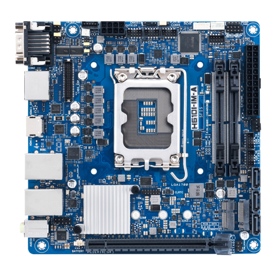
BKLTEN_SEL COM1_SEL HDMI1_DP HDMI2 Place this side towards the rear LGA1700 of the chassis Intel ® I210AT LAN2_U32G1_34 128Mb BIOS Intel ® I219V CLRTC LAN1_U32G1_12 Intel ® H610 M.2(SOCKET3) 2280 2260 2242 PCIE SATA AUDIO 3.0 X4 PCIEX16(G4) BATTERY H610I-IM-A... - Page 11 Connectors/Jumpers/Slots Page COM RING/+5V/+12V selection jumper (COM1/2_SEL) 2-12 LCD Panel monitor switch header (2-pin PANEL_SW) 2-24 LVDS Backlight Panel header (5-pin LCD_BLKT_PANEL) 2-25 ATX Power connector (24-pin ATXPWR, 2 x 4-pin EATX12V) 2-16 Intel LGA1700 CPU socket ® Chassis Intrusion header (4-1 pin CHASSIS) 2-20 AT/ATX mode selection jumper (3-pin AT_ATX_SEL) 2-12...
-
Page 12: Central Processing Unit (Cpu)
Merchandise Authorization (RMA) requests only if the motherboard comes with the cap on the LGA1700 socket. • The product warranty does not cover damage to the socket contacts resulting from incorrect CPU installation/removal, or misplacement/loss/ incorrect removal of the PnP cap. H610I-IM-A... -
Page 13: Installing The Cpu
2.3.1 Installing the CPU • Ensure that you install the correct CPU designed for LGA1700 socket only. DO NOT install a CPU designed for LGA1155, LGA1156, LGA1151, and LGA1200 sockets on the LGA1700 socket. • ASUS will not cover damages resulting from incorrect CPU installation/ removal, incorrect CPU orientation/placement, or other damages resulting from negligence by the user. - Page 14 H610I-IM-A...
-
Page 15: Cpu Heatsink And Fan Assembly Installation
2.3.2 CPU heatsink and fan assembly installation CAUTION! Apply the Thermal Interface Material to the CPU heatsink and CPU before you install the heatsink and fan if necessary. To install the CPU heatsink and fan assembly Chapter 2: Motherboard information... - Page 16 • We recommend using a LGA1700 compatible cooling system on an Intel 600 series ® motherboard. • Push-pin type LGA1200 compatible cooling systems cannot be installed to this motherboard. LGA1700 To uninstall the CPU heatsink and fan assembly H610I-IM-A...
-
Page 17: System Memory
System memory This motherboard comes with two Double Data Rate 4 (DDR4) Dual Inline Memory Module (DIMM) sockets. The figure below illustrates the location of the DDR4 DIMM sockets: Channel Sockets Channel A DIMM_A1 Channel B DIMM_B1 IMPORTANT! • You may install varying memory sizes in Channel A and Channel B. The system maps the total size of the lower-sized channel for the dual-channel configuration. - Page 18 Recommended memory configuration DIMM_A1* DIMM_B1* DIMM_A1* DIMM_B1* Installing a DIMM To remove a DIMM H610I-IM-A 2-10...
-
Page 19: Jumpers
Jumpers Clear RTC RAM (2-pin CLRTC) This header allows you to clear the CMOS RTC RAM data of the system setup information such as date, time, and system passwords. CLRTC PIN 1 Connector type HEADER 1x2p, 2.54mm pitch, S/T To erase the RTC RAM: Turn OFF the computer and unplug the power cord. - Page 20 COM Ring/+5V/+12V selection jumper (6-pin COM1/2_SEL) COM2_SEL COM1_SEL +12V (Default) Setting Pins +12V Ring (Default) AT/ATX mode selection jumper (3-pin AT_ATX_SEL) AT_ATX_SEL ATX mode AT mode (Default) Pins 1-2 (Default) ATX mode AT mode Connector type HEADER 1x3p, 2.54mm pitch, S/T H610I-IM-A 2-12...
- Page 21 LVDS Panel Backlight Enable Signal Selection jumper (BKLTEN_SEL) BKLTEN_SEL High Active Low Active (Default) BKLTEN_SEL Pins HIGH active LOW active Connector type HEADER 1x3p, 2.54mm pitch, S/T LVDS Panel VCC Power Selection jumper (6-pin VCC_PWR_SEL) VCC_PWR_SEL (Default) Setting Pins 3V (Default) Connector type HEADER 1 x 3p, 2.54mm pitch, S/T Chapter 2: Motherboard information...
-
Page 22: Connectors
4.1, and 5.1 channel configurations, the function of this port becomes Front Speaker Out. Microphone port (pink). This port connects to a microphone. Refer to the audio configuration table for the function of the audio ports in 2, 4, 5.1, or 7.1-channel configuration. H610I-IM-A 2-14... - Page 23 Audio 2, 4, 5.1 or 7.1-channel configuration Headset Port 4-channel 5.1-channel 7.1-channel 2-channel Lime (Rear panel) Line Out Front Speaker Out Front Speaker Out Front Speaker Out Pink (Rear panel) Mic In Mic In Bass/Center Bass/Center Lime (Front panel) Side Speaker Out To configure a 7.1-channel audio output: Use a chassis with HD audio module in the front panel to support a 7.1-channel audio output.
-
Page 24: Internal Connectors
WAFER HD 4p, 2.54mm pitch, S/T CAUTION: Do not forget to connect the fan cables to the fan headers. Insufficient air flow inside the system may damage the motherboard components. These are not jumpers! Do not place jumper caps on the fan headers! H610I-IM-A 2-16... - Page 25 USB 2.0 headers (10-1 pin USB56, USB78) These headers are for USB 2.0 ports. Connect a USB cable to the header. The USB headers comply with USB 2.0 specification that supports up to 480 Mbps connection speed. USB_78 PIN 10 USB_P7+ USB_P8+ USB_P7-...
- Page 26 S_CNV_RGI_DT S_CNV_RGI_RSP S_CNV_BRI_DT S_WIFI_TXP_C CL_RST# S_WIFI_TXN_C CL_DATA CL_CK S_WIFI_RXP CNVI_GNSS_R S_WIFI_RXN MFUART2_TXD_R MFUART2_RXD_R CK_WIFI_CLKP S_SUSCLK_R CK_WIFI_CLKN S_PLTRST# S_BT_DISABLE_N CK_REQ_M2_WLAN#_R S_WIFI_DISABLE_N S_WAKE#_WIFI S_CNV_WT_D1_N S_CNV_WT_D1_P CNV_CLKIN_XTAL_R S_CNV_WT_D0_N S_CNV_WT_D0_P +3VSB_WIFI S_CNV_WT_CLK_N +3VSB_WIFI S_CNV_WT_CLK_P NOTE: The M.2 Wi-Fi module is purchased separately. H610I-IM-A 2-18...
- Page 27 System Panel header (10-1 pin F_PANEL) This header supports several chassis-mounted functions. +PWR_LED- PWR_BTN PIN 2 F_PANEL PIN 1 PIN 9 +HDD_LED- RESET Connector type HEADER 2x5p, K10, 2.54mm pitch • System power LED (2-pin +PWR_LED) This 2-pin header is for the system power LED. Connect the chassis power LED cable to this header.
- Page 28 The chassis intrusion sensor or switch sends a low-level signal to this connector when a chassis component is installed. The signal is then generated as a chassis intrusion event. CHASSIS PIN 1 Connector type HEADER 4p, K2, 2.54mm pitch H610I-IM-A 2-20...
- Page 29 10. SATA 6.0Gb/s ports (7-pin SATA6G_1-4) These ports connect to SATA 6.0 Gb/s hard disk drives or an optical drive via SATA 6.0 Gb/s signal cables. SATA6G_3 SATA6G_2 SATA6G_1 RSATA_RXP RSATA_RXN RSATA_TXN RSATA_TXP Connector type SATA CON 7P S/T 11. General Purpose Input/Output header (GPIO_CON) This header is for a general purpose input/output module which allows you to customize the digital signal input/output.
- Page 30 PIN 2 PIN 1 PIN 9 Connector type HEADER 2x5p, K10, 2.54mm pitch NOTE: The serial port cable is purchased separately. 13. RTC Battery header (2-pin BATTERY) This header is for the lithium CMOS battery. BATTERY PIN 1 H610I-IM-A 2-22...
- Page 31 14. Front Panel Audio header (10-1 pin AAFP) This header is for a chassis-mounted front panel audio I/O module that supports HD Audio standard. Connect one end of the front panel audio I/O module cable to this header. PIN 2 PIN 10 AAFP PIN 1...
- Page 32 NOTE: The COM Debug Card is purchased separately. 16. LCD Panel monitor switch header (2-pin PANEL_SW) This 2-pin header is for connecting a monitor switch that can turn on/off the LCD panel display backlight. PANEL_SW PIN 1 MON_SW# H610I-IM-A 2-24...
- Page 33 17. LVDS Backlight Panel header (5-pin LCD_BLKT_PANEL) This header is for the LCD panel brightness controls. LCD_BLKT_PANEL LVDS Signal eDP Signal PIN1 PIN1 Connector type WAFER 6p, 2.0mm pitch 18. LVDS/EDP header (40-pin LVDS_EDP) This header is for an internal LVDS or embedded DisplayPort connection. LVDS_EDP LVDS Signal EDP Signal...
- Page 34 19. PCIe 4.0 x16 slot (PCIEX16(G4)) This slot supports a PCIe 4.0 x16 graphics card that complies with the PCI Express specification. PCIEX16(G4) H610I-IM-A 2-26...
-
Page 35: Chapter 3 Bios Setup
Chapter 3 BIOS setup Chapter 3 BIOS setup Scan the QR code to view the BIOS update guide. BIOS setup program Use the BIOS Setup program to update the BIOS or configure its parameters. The BIOS screens include navigation keys and brief online help to guide you in using the BIOS Setup program. -
Page 36: Bios Menu Screen
The Main menu provides you an overview of the basic system information, and allows you to set the system date, time, language, and security settings. 3.2.1 System Date [Day MM/DD/YYYY] Allows you to set the system date. 3.2.2 System Time [HH:MM:SS] Allows you to set the system time. H610I-IM-A... -
Page 37: Advanced Menu
Advanced menu The Advanced menu items allow you to change the settings for the CPU and other system devices. Be cautious when changing the settings of the Advanced menu items. Incorrect field values can cause the system to malfunction. 3.3.1 LVDS Configuration The items in this menu show the LVDS-related information that the BIOS automatically detects. -
Page 38: Pch-Fw Configuration
® power cyle. Configuration options: [Disabled] [Enabled] VT-d [Disabled] Allows you to enable or disable VT-d function on MCH. Configuration options: [Disabled] [Enabled] CPU - Power Management Control This item allows you to manage and configure the CPU’s power. H610I-IM-A... -
Page 39: Graphics Configuration
Intel(R) SpeedStep(tm) This item allows your system to support more than two frequency ranges. Configuration options: [Disabled] [Enabled] Intel(R) Speed Shift Technology This item allows you to enable or disable Intel(R) Speed Shift Technology support. When enabled, CPPC v2 interface allows hardware controlled P-state. -
Page 40: Power Management
Use the <+> and <-> keys to adjust the value or input the desired value. Detect Non-Compliance Device Allows you to enable or disable the detection function of non-compliance PCI Express device. Configuration options: [Disabled] [Enabled] H610I-IM-A... -
Page 41: Super Io Configuration
3.3.8 Super IO Configuration NCT6126D Super IO Configuration Serial Port 1 Configuration Serial Port Allows you to enable or disable the serial port (COM).Configuration options: [Disabled] [Enabled] The following items appear only when you set Serial Port to [Enabled]. COM1 Control Allows you to select the COM1 mode. Configuration options: [RS232] [RS422] [RS485] Serial Port 2 Configuration Serial Port... -
Page 42: Serial Console Redirection
Communication with slow devices may require more than 1 stop bit. Configuration options: [1] [2] Flow Control Flow control can prevent data loss from buffer overflow. When sending data, if the receiving buffers are full, a “stop” signal can be sent to stop the H610I-IM-A... -
Page 43: Sata Configuration
data flow. Once the buffers are empty, a “start” signal can be sent to re-start the flow. Hardware flow control uses two wires to send start/stop signals. Configuration options: [None] [Hardware RTS/CTS] VT-UTF8 Combo Key Support Allows you to enable or disable VT-UTF8 Combination Key Support for ANSI/ VT100 terminals. -
Page 44: Network Stack Configuration
NVMe device options settings. 3.3.14 Onboard Devices Configuration HD Audio [Enabled] Enables the HD Audio Device. [Disabled] Disables the HD Audio Device. LAN1 I219 [Enabled] Enables the Intel LAN1 controller. [Disabled] Disables the controller. H610I-IM-A 3-10... -
Page 45: Apm Configuration
LAN2 I210 [Enabled] Enables the Intel LAN2 controller. [Disabled] Disables the controller. M.2 WiFi Allow you to enable or disable M.2 WiFi function. Configuration options: [Enabled] [Disabled] M.2 BT Allow you to enable or disable M.2 BT function. Configuration options: [Enabled] [Disabled] 3.3.15 APM Configuration... -
Page 46: Ez-Flash
Smart Fan Mode Allows you to select the smart fan mode. Configuration options: [Disabled] [Normal] [Manual Mode] The following item appears only when you set Smart Fan Mode to [Manual Mode]. H610I-IM-A 3-12... -
Page 47: Security Menu
Smart Fan Function System Fan Setting Chassis Fan Temperature 1(~4) Allows you to set the value of temperature1(~4). Chassis Fan FD/RPM 1(~4) Allows you to set the value of Fan Duty/PRM 1(~4) when temperature is T1(~4). CPU Fan Setting CPU Fan Temperature 1(~4) Allows you to set the value of temperature1(~4). -
Page 48: Boot Menu
65535(0xFFFF) means indefinite waiting. Configuration options: [1] - [65535] Post Time Delay This item allows you to select the desired additional POST waiting time to easily enter the BIOS setup. (Delay time = value * 500ms). Configuration options: [0] - [12] H610I-IM-A 3-14... -
Page 49: Exit Menu
Boot up NumLock State [On] Set the power-on state of the NumLock to [On]. [Off] Set the power-on state of the NumLock to [Off]. Quiet Boot Allows you to enable or disable the Quiet Boot option. Configuration options: [Disabled] [Enabled] Fast Boot [Enabled] Select to accelerate the boot speed. - Page 50 Restore/load default values for all the setup options. Save as User Defaults This option allows you to save the changes you have made so far as user defaults. Restore User Defaults Restore the user defaults with all the setup options. H610I-IM-A 3-16...
-
Page 51: Appendix
Appendix Appendix Notices FCC Compliance Information Responsible Party: Asus Computer International Address: 48720 Kato Rd., Fremont, CA 94538, USA Phone / Fax No: (510)739-3777 / (510)608-4555 This device complies with part 15 of the FCC Rules. Operation is subject to the following two conditions: (1) This device may not cause harmful interference, and (2) this device must accept any interference received, including interference that may cause undesired operation. - Page 52 CAN ICES-003(B)/NMB-003(B) VCCI: Japan Compliance Statement Class B ITE KC: Korea Warning Statement HDMI Trademark Notice The terms HDMI, HDMI High-Definition Multimedia Interface, and the HDMI Logo are trademarks or registered trademarks of HDMI Licensing Administrator, Inc. H610I-IM-A...
- Page 53 REACH Complying with the REACH (Registration, Evaluation, Authorisation, and Restriction of Chemicals) regulatory framework, we published the chemical substances in our products at ASUS REACH website at http://csr.asus.com/english/REACH.htm. DO NOT throw the motherboard in municipal waste. This product has been designed to enable proper reuse of parts and recycling.
- Page 54 Directives. Full text of EU declaration of conformity is available at: www.asus.com/support www.asus.com/support Srpski ASUSTeK Computer Inc. ovim izjavljuje da je ovaj uređaj u saglasnosti Français AsusTek Computer Inc. déclare par la présente que cet appareil est sa osnovnim zahtevima i drugim relevantnim odredbama povezanih conforme aux critères essentiels et autres clauses pertinentes des directives...
-
Page 55: Service And Support
Service and Support Visit our multi-language website at https://www.asus.com/support/ Appendix...
Need help?
Do you have a question about the H610I-IM-A and is the answer not in the manual?
Questions and answers