Table of Contents
Advertisement
Quick Links
Advertisement
Table of Contents

Subscribe to Our Youtube Channel
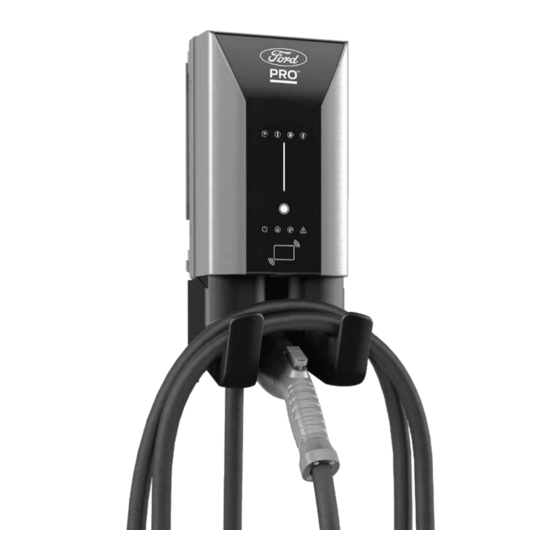
Summary of Contents for Ford Pro AC Charging Station 48A
- Page 1 Quick Start Installation Guide Ford Pro ™ Charging Station 48A...
-
Page 2: Table Of Contents
Limited Warranty ................20 Ford Pro contact info: chargingsupport@fordpro.com and 1-800-34-FLEET... - Page 3 Figure 17. Commercial HMI ............... . 13 Ford Pro contact info: chargingsupport@fordpro.com and 1-800-34-FLEET...
-
Page 4: Installation Kit
NOTE: 1. Wire must have a temperature rating of 90° C or higher. 2. Do not set the amp switch higher than 40A unless hard- wired to a dedicated 60A branch protection circuit breaker. Ford Pro contact info: chargingsupport@fordpro.com and 1-800-34-FLEET... - Page 5 5 – #12 x 1-1/2" LG Phillips head 0.375 head minimum, with 5 – #12 wall anchors (NOTE: Wall anchors must be rated for 61 lbs. for 1/2" dry wall.) Ford Pro contact info: chargingsupport@fordpro.com and 1-800-34-FLEET...
-
Page 6: Bracket Mounting
Figure 5. Set Amp Switch Figure 6. Charger Hardwiring and (Commercial/Residential – See page 8) (Commercial/Residential – See page 8) Ferrite Core Installation (Commercial/ Residential – See page 9. See Appendix C for wire bending diagram) Ford Pro contact info: chargingsupport@fordpro.com and 1-800-34-FLEET... -
Page 7: Figure 7. Sim Card Installation
Figure 11. Commercial Child ModBus Figure 12. External Remote Control Termination Switch Setting (Commercial Termination Switch Setting (Commercial Interface (Commercial Only – Only – See page 10) Only – See page 10) See page 11) Ford Pro contact info: chargingsupport@fordpro.com and 1-800-34-FLEET... -
Page 8: Figure 13. Close Charger
STEP 10 STEP 11 STEP 12 Figure 13. Close Charger Figure 14. Secure Charger Figure 15. Holster Installation (Commercial/Residential – See page 11) (Commercial/Residential – See page 11) (Commercial/Residential – See page 11) Ford Pro contact info: chargingsupport@fordpro.com and 1-800-34-FLEET... -
Page 9: Outlet Installation
40-amp charger), and 0–5 amperage adjustment settings are used for the 48-amp charger. Setting the amperage adjustment higher than 5 will result in a fault. Ford Pro contact info: chargingsupport@fordpro.com and 1-800-34-FLEET... - Page 10 Push the Ethernet cable through the rubberized gland and snake it up through the back to the opening. Connect the Ethernet RJ45 plug to the cable. Insert the RJ45 plug from the bottom up into the Ethernet port. Ford Pro contact info: chargingsupport@fordpro.com and 1-800-34-FLEET...
- Page 11 Termination Switch – Termination switch must be set to OFF, unless the unit is the last one in the daisy chain, then the Commercial Child Units switch must be set to ON. Only (Figure 11) Ford Pro contact info: chargingsupport@fordpro.com and 1-800-34-FLEET...
- Page 12 With the Power Available light on, plug the Electric Vehicle Supply Equipment (EVSE) cable into the vehicle. If you have any fault lights, please see the HMI figures in the beginning of this manual. Ford Pro contact info: chargingsupport@fordpro.com and 1-800-34-FLEET...
-
Page 13: Maintenance
Check for snow buildup around the charger and clear the area around the charger. This should be checked daily in areas with high snowfall. Ford Pro contact info: chargingsupport@fordpro.com and 1-800-34-FLEET... -
Page 14: Appendix A - Human Machine Interface (Hmi)
* Accept beep increases in length of time/Failure beep decreases in length of time. Figure 17. Commercial HMI NOTE: Number of LEDs may change based on specific part number and features. The Bluetooth word mark is a trademark of the Bluetooth SIG, Inc. Ford Pro contact info: chargingsupport@fordpro.com and 1-800-34-FLEET... -
Page 15: Appendix B - System Operation/Faults
Access Point mode. charger is ready to be added to the account. Lights up red. No Wi-Fi signal. Check the router. Lights up orange. Charger is connected to router. Weak Wi-Fi. Strengthen the Wi-Fi signal. Ford Pro contact info: chargingsupport@fordpro.com and 1-800-34-FLEET... - Page 16 Press Touch Sensitive Button Press the Touch Sensitive Button once for 2-hour to add a time delay. delay, twice for 4-hour delay, three times for 6-hour delay and four times for 8-hour delay. Ford Pro contact info: chargingsupport@fordpro.com and 1-800-34-FLEET...
- Page 17 A fault has occurred. Error code: 003. Notify Technical Support. Lights up red. A fault has occurred. Error code: 004. Notify Technical Support. Lights up red. A fault has occurred. Error code: 005. Notify Technical Support. Ford Pro contact info: chargingsupport@fordpro.com and 1-800-34-FLEET...
- Page 18 Error code: 0010. Notify Technical Support. Cold Start – Lights Random delay of 1–5 minutes on power No Action. up steady white. cycle if EV is connected. EVSE will resume charging a er delay expires. Ford Pro contact info: chargingsupport@fordpro.com and 1-800-34-FLEET...
-
Page 19: Appendix C- Hardwire Bending Diagram
NOTE: The rating of the circuit breaker that will be required is based on the ampere rating of the EVSE; 40A requires 50A breaker; 48A requires 60A breaker. Also, the wiring should not be exposed to weather/water or conditions that could potentially damage wiring or cause a short. Ford Pro contact info: chargingsupport@fordpro.com and 1-800-34-FLEET... -
Page 20: Legal Manufacturer
Siemens reserves the right to modify the technology and product specifications in its sole discretion without advance notice. © 2021 by Siemens Industry, Inc. This document has been modified by Ford Pro to incorporate Ford Pro branding and nomenclature.


Need help?
Do you have a question about the Pro AC Charging Station 48A and is the answer not in the manual?
Questions and answers