
Related Manuals for Konica Minolta MYIRO-1


Summary of Contents for Konica Minolta MYIRO-1
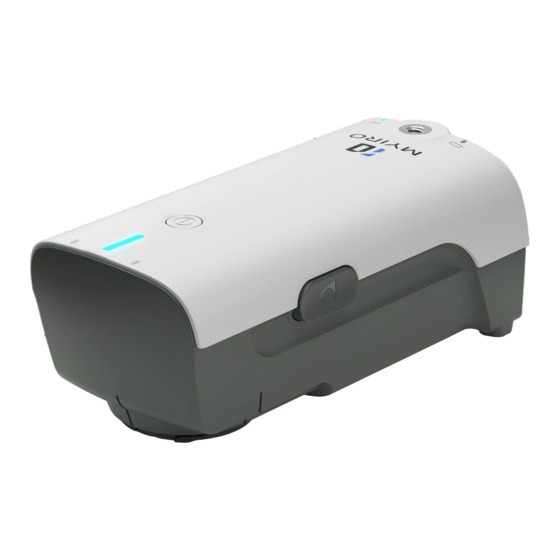
- Page 1 MYIRO-1 Introduction Instruction Manual [Rev 1.01] KONICA MINOLTA, INC. R&D Division, Sensing Business Unit ンシング事業部 開発部...
- Page 2 System configuration Standard accessories...
- Page 3 Indicates the battery status of the battery remaining capacity and charging. ⑤ Battery indicator It is used to connect MYIRO-1 and PC with USB cable. Besides communication ⑥ USB connection terminal with the PC, it is also used for charging.
- Page 4 Attaching / removing the ambient light attachment Used for ambient light measurements. How to install 1 You can install the ambient light attachment by turning the ▲ mark in the right figure in the direction of the arrow. How to uninstall You can uninstall the ambient light attachment by turning the ▲...
- Page 5 Pushing the power button from the ON state turns off the power. Auto power off function MYIRO-1 has “auto power off” function, and when communication doesn’t operate for a certain period of time, the power turns off automatically. To turn on the power again, press the power button. At this time, the connection with the application is disconnected and the calibration data is deleted, so it is necessary to reconnect with the application and recalibrate.
- Page 6 Calibration There are the following types of calibrations, but in either case the work in MYIRO-1 is the same. For Chart measurement For Ambient light measurement For Display measurement Procedure 8-1 Attach the white calibration cap to the measurement opening.
- Page 7 After mounting the cap) Note:When not using the measuring instrument, keep it with the calibration cap attached to prevent dust adhesion. Reference) At the time of measurement, the calibration cap can be stored as shown below.
- Page 8 8-2 White calibration is performed by measurement button or control from SDK. When white calibration is performed, the status indicator changes as follows depending on the calibration status. Status indicator Status Explanation Supplementary explanation Lighting up(Yellow) Uncalibrated uncalibrated condition, calibration is necessary to measure.
- Page 9 Scanning measurement Set the ruler on the chart so that the △ mark(Red arrow in the figure) of the ruler matches the left edge of the chart. Measurement range Set MYIRO - 1 to the left edge of the ruler. The scan operation needs to start from the paper white part. If you keep pushing the measurement button and the status indicator changes from blue to white, slide MYIRO - 1 as it is.
- Page 10 10. Spot measurement Adjust the spot target of the ruler to the part to be measured. Place the measurement opening of MYIRO-1 so that it meets the spot target, and perform measurement with the measurement button or control from the SDK.
- Page 11 Inter-instrument agreement Within ⊿E00 0.3 * Average of 12 BVRA Series Ⅱ color tiles compared to values measured with a master body under Konica Minolta standard conditions Measurement time Spot Measurement:Approx. 1 second Scan Measurement: Approx.1 second (Press the measurement button and then start scanning) Approx.
- Page 12 10 to 35℃、30 to 85% relative humidity with no condensation Operating temperature/humidity range Storage 0 to 45℃、0 to 85%relative humidity with no condensation temperature/humidity range Chart specification ② Item Specification Supplementary explanation 270 ㎜ Chart Scanning range Maximum chart width 257 ㎜...
- Page 13 Scanning direction n Perpendicular directionn Item Specification Supplementary explanation Gap Condition 1 line or black and white doublet Color difference Color difference from one There is no problem in black and between gap and patch white double lines. patch ΔE*ab >20 0.5 to 1.0 ㎜...
- Page 14 Revision history Date Rev. Revised content 2019/05/20 1.00 First edition 8. 2019/05/23 1.01 Calibration (Add description of calibration cap )...
Need help?
Do you have a question about the MYIRO-1 and is the answer not in the manual?
Questions and answers