Table of Contents
Advertisement
Quick Links
Advertisement
Table of Contents

Related Manuals for Major tech MT26


Summary of Contents for Major tech MT26
- Page 1 INSTRUCTION MANUAL MT26 600V AC/DC BLUETOOTH MULTIMETER...
-
Page 3: Table Of Contents
Contents Page no 1. Introduction ..................4 1.1. Input Limits ................5 1.2. General Specfications ..............5 1.3. International Safety Symbols ............6 2. Safety Category Ratings ..............6 2.1. Maintenance ................7 2.2. Meter Description ..............8 2.3. Symbols Used on LCD Display ...........8 3. Operation ..................9 3.1. -
Page 4: Introduction
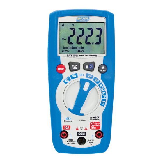
1. INTRODUCTION The MT26 is a CAT III 600V True RMS compact multimeter offering measurements of AC and DC voltage, AC and DC current, frequency, capacitance, resistance and temperature. The meter has a large 4000 count backlit LCD with the added advantage of an analogue bar graph. -
Page 5: Input Limits
1.1. INPUT LIMITS Maximum Input Function Voltage AC or DC 600V AC RMS/600V DC LowZ 300V AC RMS/300V DC Current AC or DC 10A 600V fast acting fuse (10A for 30 seconds max. every 15 minutes) Resistance, Continuity, Diode Test, Capacitance, Frequency, Duty Cycle 600V AC RMS/600V DC Temperature 300V AC RMS or 300V DC... -
Page 6: International Safety Symbols
1.3. INTERNATIONAL SAFETY SYMBOLS Potential danger. Indicates the user must refer to the manual for important safety information. Indicates hazardous voltages may be present. Equipment is protected by double or reinforced insulation. Indicates the terminal(s)so marked must not be connected to a circuit where the voltage with respect to earth ground exceeds the maximum safety rating of the meter. -
Page 7: Maintenance
WARNING: Operation is limited to CAT II applications when the insulated tips are removed from one or both test probes. Refer to Input Limits section in this manual for maximum voltage ratings. 2.1. MAINTENANCE This Multimeter is designed to provide years of dependable service, if the following care instructions are performed: 1. -
Page 8: Meter Description
2.2. METER DESCRIPTION 1 - LCD display 2 - MAX/MIN button 3 - MODE button 4 - Rotary function switch 5 - 10A input jack 6 - COM input jack 7 - V/ / /⁰C/⁰F input jack 8 - HOLD Backlight button 9 - Bluetooth/Flashlight button 10 - Flashlight 2.3. -
Page 9: Operation
3. OPERATION 3.1. AUTO POWER OFF The meter automatically turns off after 15 minutes of inactivity. To reset the meter after it shuts off, turn rotary function switch to the off position and then set the switch to the desired function. To disable Auto Power Off, turn the rotary function switch to the off position. -
Page 10: Hold/Backlight Button
3.5. HOLD/BACKLIGHT BUTTON To freeze the reading on the display, press the HOLD button. "HOLD" will appear on the LCD display while the reading is being held. Press the HOLD button again to return to normal operation. The backlight illuminates the LCD display when the ambient light is too low to view the displayed readings. -
Page 11: Low Z Ac/Dc Voltage Measurements
4.1. LOW Z AC/DC VOLTAGE MEASUREMENTS WARNING: Observe all safety precautions when working on live voltages. Do not connect to circuits that exceed 300V AC RMS or 300V DC when the meter is set to Low Z. Low Z is used to check for "ghost" voltage. Ghost voltages are present when non-powered wires are in close proximity to powered wires. -
Page 12: Ac Current Measurements
4.2. AC CURRENT MEASUREMENTS WARNINGS: Observe all safety precautions when working on live circuits. Do not measure current on circuits that exceed 600V. Measurements in the 10A range should be limited to 30 seconds maximum every 15 minutes. 1. Set the rotary function switch to the 10A position. -
Page 13: Frequency And % Duty Cycle Measurements
4.4. FREQUENCY AND % DUTY CYCLE MEASUREMENTS WARNING: Observe all safety precautions when working on live circuits. 1. Set the rotary function switch to the Hz % position. 2. To select Frequency or % Duty Cycle, press the MODE button until the "Hz" or "%"... -
Page 14: Diode Test
4.6. DIODE TEST WARNING: Never test diodes on a live circuit. 1. Set the rotary function switch to the position. 2. Press the MODE button until the symbol appears on the LCD display. 3. Insert the black test lead into the COM input jack and the red test lead into the Ω... -
Page 15: Capacitance Measurements
4.8. CAPACITANCE MEASUREMENTS WARNING: Safely discharge capacitors before taking capacitance measurements. 1. Set the rotary function switch to the position. 2. lnsert the black test lead into the COM input jack and the red test lead into the Ω input jack. 3. -
Page 16: Battery Replacement
4.10. BATTERY REPLACEMENT WARNING: To avoid electric shock, remove the test leads from the meter before removing the battery/fuse cover. 1. Lift up the tilt stand. 2. Loosen the two Phillips screws on the battery/fuse cover. 3. Remove the battery/fuse cover. 4. -
Page 17: Specifications
5. SPECIFICATIONS Accuracy is given at 18°C to 28°C (65°F to 83°F), less than 70% relative humidity. 5.1. AC VOLTAGE Range Resolution Accuracy 4.000V ±(1.0% + 5) 40.00V 10mV ±(1.2% + 5) 400.0V 0.1V ±(1.5% + 5) 600V Input Protection: 600V DC or 600V AC RMS Input Impedance: 10MΩ... -
Page 18: Ac Current
5.5. AC CURRENT Range Resolution Accuracy 4.000A ±(2.5% + 3) 10.00A 10mA Overload Protection: 10A/600V Fuse AC Response: 50 to 60Hz 5.6. DC CURRENT Range Resolution Accuracy 4.000A ±(2.0% + 3) 10.00A 10mA Overload Protection: 10A/600V Fuse 5.7. RESISTANCE Range Resolution Accuracy 400.0Ω... -
Page 19: Frequency
5.9. FREQUENCY Range Resolution Accuracy 9.999Hz 0.001Hz 99.99Hz 0.01Hz 999.9Hz 0.1Hz ±(1.0% + 5) 9.999kHz 1Hz 99.99kHz 10Hz 999.9kHz 100Hz ±(1.2% + 5) 9.999MHz 1kHz Input Protection: 600V DC or 600V AC RMS Sensitivity: >8V RMS 5.10. DUTY CYCLE Range Resolution Accuracy 1.0% to 99.9%... - Page 20 MAJOR TECH (PTY) LTD South Africa Australia www.major-tech.com www.majortech.com.au sales@major-tech.com info@majortech.com.au...
Need help?
Do you have a question about the MT26 and is the answer not in the manual?
Questions and answers