
Summary of Contents for Novexx Solutions HDC
- Page 1 USER MANUAL Hold down conveyor Edition 1 - 7/2015 - Translation of original version...
-
Page 3: Table Of Contents
User Manual Contents Please note General Information Validity of this manual and required compliance How information is represented For your safety Intended use Information and qualification Operating safety of the machine Every time before starting production Warning symbols on the machine Product Description Technical Data Dimensions... - Page 4 User Manual 12/2017 Contents...
-
Page 5: Please Note
Any obligation to extend these changes to machines previously delivered is excluded. Copyright NOVEXX Solutions retains all rights to this manual and its appendices. Reproduction, reprint or any other type of duplication, including parts of the manual, are permitted only with written approval. - Page 6 User Manual How information is represented Explanation of symbols To enhance readability and make information easier to find, different types of information are iden- tified: Instruction with no order of tasks assigned 1. Numbered instructions introduced by preceding text 2.
-
Page 7: For Your Safety -7
NOVEXX Solutions offers switch cabinets for the control of complete belt units. Any other type of or more extensive application will be considered non-intended use. NOVEXX Solutions shall assume no liability for damage resulting from non-intended use of the ma- chine. - Page 8 User Manual Qualification for operation The instruction provided for the operating personnel must ensure: • that the operating personnel can use the machine independently and without danger. • that the operating personnel can rectify minor operating faults independently. At least 2 persons should be instructed in operation. Qualification for system integrators and service technicians Installation of the machine and service work on the machine require appropriate qualifica- tion.
-
Page 9: Operating Safety Of The Machine -9
Improper use of the machine can result in accidents, property damage and loss of production! Inspect the machine closely for visible transport damage during installation. In the event of damage, notify NOVEXX Solutions immediately. Do not install the machine in potentially explosive environments. - Page 10 User Manual After all maintenance and repair work WARNING! Risk of accidents from moving or loose parts! Install all covers and protective equipment again. Check all bolted connections loosened or removed during work for tightness again. Remove all tools and other equipment used for the maintenance or repair work from the work- ing area of the machine.
-
Page 11: Every Time Before Starting Production -11
User Manual Warning of injury hazards from mechanical components WARNING! Danger of injury due to moving and rapidly rotating parts! Maintain a safety clearance from the machine when it is in operation. Never reach into a machine that is running. ... -
Page 12: Warning Symbols On The Machine -12
User Manual Warning symbols on the machine [1] Warning symbols on the hold down conveyor CAUTION! Warning symbols on the machine provide important information for the operating personnel. Do not remove warning symbols. Replace missing or illegible warning symbols. ... -
Page 13: Product Description
User Manual Product Description TECHNICAL DATA Dimensions Dimensions [2] Dimensions of the hold down conveyor. • L = 300mm or 600mm (for 300mm, only one clamp) • B = 45mm or 95mm 12/2017 | 00 Product Description... -
Page 14: Performance Data -14
Ambient conditions Installation location • Inside buildings • Protected from water and wind • Dry • Non-explosive atmosphere NOVEXX Solutions belt conveyor (B-Conveyor) or chain belt conveyor (CB-Conveyor) 12/2017 | 00 Product Description... -
Page 15: Certificates -15
User Manual Operating temperature +5 to +40°C Storage temperature 0 to +70°C Relative humidity 30 to 80% RH (non-condensing) Noise emissions < 70dB(A) Certificates CE, TÜV mark, GOST Standard DIN EN 55022 stipulates the following instruction text for class A machines: "WARNING! This is class A equipment. -
Page 16: Overview -16
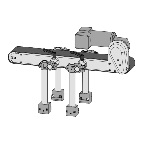
The hold down conveyor is used to press products onto the belt conveyor so that they can be aligned or held. The hold down conveyor is installed on a NOVEXX Solutions belt conveyor unit and can be used in combination with other auxiliary belts such as alignment unit or wrap around con- veyor. - Page 17 User Manual Etiketten- spender Leichte Produkte Niederhalteband Schaltschrank mit Etiketten- Motorsteuerung spender [3] Application of the hold down conveyor (example, schematic). [4] Functional elements of the hold down conveyor A Hold-down conveyor B Mounting clamps (for 300 mm hold down conveyor only one clamp) C Terminal box for the drive motor D Drive motor E Belt drive...
-
Page 18: Switching On/Off -18
The ON/OFF switch is installed by the operating company. The switch is normally located on the switch cabinet of the motor controller [5A]. [5] ON/OFF switch (A) on the switch cabinet of the motor controller (Example: NOVEXX Solutions, AMC Series). 12/2017 | 00 Product Description... -
Page 19: Commissioning -19
Improper use of the machine can result in accidents, property damage and loss of production! Inspect the machine closely for visible transport damage during installation. In the event of damage, notify NOVEXX Solutions immediately. Do not install the machine in potentially explosive environments. -
Page 20: Installation -20
User Manual INSTALLATION Install the motor If the hold down conveyor was supplied without motor (option), a motor first has to be installed. The motor must satisfy the following requirements: • Torque: max. 10Nm • Speed: max. 120rpm • Pitch circle diameter: 80mm [6] Dimensions of the motor flange. -
Page 21: Installing Hold Down Conveyor -21
The holders supplied with the hold down conveyor are designed for installation on belt conveyors from NOVEXX Solutions. Depending on its length, the hold down conveyor is in- stalled with one (l = 300mm) or two (l = 600mm) hold- ers. - Page 22 User Manual [13] Installation position of the hold down conveyor A Hold-down conveyor on belt conveyor. B Clamps for alignment and fixing of the hold down conveyor on the belt conveyor. C Holders. D Belt conveyor (accessory). E Support stand (accessory). 12/2017 | 00 Commissioning...
-
Page 23: Connection -23
[14] Potentiometer (A) on the switch cabinet of the motor control- ler (example: NOVEXX Solutions, AMC Series). Recommended: Lenze 532; The motor controller must be able to switch off the motor in the event of a fault. -
Page 24: Cleaning -24
User Manual Cleaning CLEANING INSTRUCTIONS Safety WARNING! Dangerous situations may arise during maintenance and cleaning work. Accidents may occur due to mechanical or electrical effects if the relevant safety instructions are not observed! Switch off the machine before starting cleaning or maintenance work! ... -
Page 25: Maintenance -25
User Manual MAINTENANCE Maintenance instructions The following parts of the hold down conveyor are subject to wear and should be inspected and replaced, if necessary, at the given intervals. Dimen- Part Inspection Coating Item No. sion 45 x 300 0001361-01 45 x 600 0001361-02 Vulkollan... - Page 26 User Manual 3. Loosen the two tensioner screws [16A] to relieve the belt tension. [16] Tensioner screws. 4. The tensioner roller moves inwards [17], the belt tension is relieved and the belt can be re- moved. [17] Tensioner roller. 5. Install a new belt (use only OEM spare parts). 6.
- Page 28 Novexx Solutions GmbH Ohmstraße 3 85386 Eching Germany +49-8165-925-0 www.novexx.com...
Need help?
Do you have a question about the HDC and is the answer not in the manual?
Questions and answers