Table of Contents
Advertisement
Quick Links
Advertisement
Chapters
Table of Contents

Related Manuals for ProLights LUMIPIX


Summary of Contents for ProLights LUMIPIX
- Page 1 LUMIPIX MULTI-BEAM EFFECT Manuale Utente User Manual...
- Page 2 Music & Lights S.r.l. si riserva ogni diritto di elaborazione in qualsiasi forma delle presenti istruzioni per l’uso. La riproduzione - anche parziale - per propri scopi commerciali è vietata. Al fine di migliorare la qualità dei prodotti, la Music&Lights S.r.l. si riserva la facoltà di modificare, in qualunque momento e senza preavviso, le specifiche menzionate nel presente manuale di istruzioni.
-
Page 3: Table Of Contents
4. 1 Manutenzione e pulizia del sistema ottico 4. 2 Sostituzione fusibile 4. 3 Risoluzione dei problemi Certificato di garanzia Contenuto dell'imballo: • LUMIPIX • Staffa di fissaggio • Staffe di fissaggio a L (2pz) • Cavo di alimentazione • Manuale utente... -
Page 4: Avvertenze Generali
LUMIPIX ATTENZIONE! Prima di effettuare qualsiasi operazione con l’unità, leggere con attenzione questo manuale e conservarlo accuratamente per riferimenti futuri. Contiene informazioni importanti riguardo l’installazione, l’uso e la manutenzione dell’unità. SICUREZZA Avvertenze generali • I prodotti a cui questo manuale si riferisce sono conformi alle Direttive della Comunità Europea e per- tanto recano la sigla . -
Page 5: Informazioni Generali
LUMIPIX INFORMAZIONI GENERALI Spedizioni e reclami Le merci sono vendute “franco nostra sede” e viaggiano sempre a rischio e pericolo del distributore/clien- te. Eventuali avarie e danni dovranno essere contestati al vettore. Ogni reclamo per imballi manomessi dovrà essere inoltrato entro 8 giorni dal ricevimento della merce. -
Page 6: Introduzione
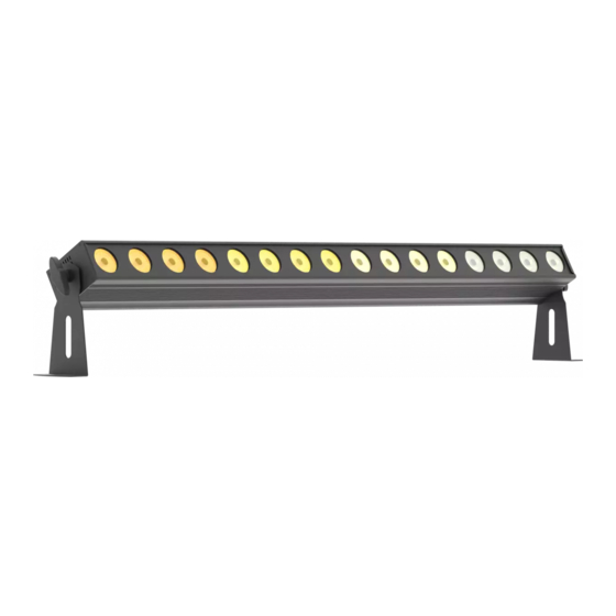
1.1 DESCRIZIONE LUMIPIX è un cambiacolori lineare, munito di 12 LED Tri-colour ad alta efficienza luminosa e in formato da 1mt. Il sistema di gestione è personalizzabile, in linea con le esigenze di utilizzo, da 3 a 36 canali di gestione in modalità... -
Page 7: Elementi Di Comando E Di Collegamento
LUMIPIX 1.3 ELEMENTI DI COMANDO E DI COLLEGAMENTO Dettaglio A Dettaglio B Fig.2 1. STAFFA DI MONTAGGIO 6. DMX OUT (XLR a 5 poli): 2. MANOPOLA DI FISSAGGIO per la staffa di 1= massa, 2 = DMX -, 3 = DMX +, 4N/C, 5N/C montaggio 7. -
Page 8: Installazione
- 2 - INSTALLAZIONE 2.1 MONTAGGIO Il LUMIPIX può essere collocato su un piano solido. Inoltre, grazie alle possibilità di fissaggio sulla doppia staffa (fig.3), l’unità può essere montata anche a testa in giù, su una traversa. Per il fissaggio occorrono dei supporti robusti per il montaggio. -
Page 9: Funzioni E Impostazioni
Per spegnere il LUMIPIX, staccare la spina dalla presa di rete. Per maggiore comodità è consigliabile collegare l’unità con una presa comandata da un interruttore. 3.2 IMPOSTAZIONE BASE Il proiettore LUMIPIX dispone di un LED display e 4 pulsanti per accesso alle funzioni del pannello di con- trollo (fig.4). Fig.4... -
Page 10: Struttura Menu
LUMIPIX 3.3 STRUTTURA MENU MAIN FUNCTION SELECTION1 SUB-SELECTION DESCRIPTION Select one of the preset colors: red, green, blue, cyan, ma- Static Color C_ _1-7 genta, yellow, white Select one of the program: 7 color switching, 7 color fading, 3 Automatic Program... -
Page 11: Modalità Color Mixing
Per questa modalità è necessario impostare correttamente le unità: IMPOSTAZIONE UNITÀ MASTER • Servirsi dei connettori DMX del LUMIPIX e di un cavo XLR per formare una catena di unità. • Impostare una delle modalità standalone per l’unità master. IMPOSTAZIONE UNITÀ SLAVE • Premere il tasto MENU fino a quando sul display non appare [SLAV], quindi premere ENTER per confermare. -
Page 12: Collegamenti Della Linea Dmx
LUMIPIX 3.11 COLLEGAMENTI DELLA LINEA DMX La connessione DMX è realizzata con connettori standard XLR. Utilizzare cavi schermati, 2 poli ritorti, con impedenza 120Ω e bassa capacità. Per il collegamento fare riferimento allo schema di connessione riportato di seguito: DMX - INPUT... -
Page 13: Tabella Canali Dmx
LUMIPIX 3.13 TABELLA CANALI DMX CH Function in CH7 mode Value RED 0-100% 000 - 255 GREEN 0-100% 000 - 255 BLUE 0-100% 000 - 255 COLOR MACRO No function 000 - 015 Color macro 016 - 255 SPEED Slow to fast (when CH6 is from 032 - 233) - Page 14 LUMIPIX Section CH Function in CH6 mode Value RED 0-100% 000 - 255 SECTION 1 GREEN 0-100% 000 - 255 BLUE 0-100% 000 - 255 RED 0-100% 000 - 255 GREEN 0-100% SECTION 2 000 - 255 BLUE 0-100% 000 - 255 SECT.
- Page 15 LUMIPIX Section CH Function in CH12 mode Value CH12 RED 0-100% 000 - 255 GREEN 0-100% SECTION 1 000 - 255 BLUE 0-100% 000 - 255 RED 0-100% 000 - 255 SECTION 2 GREEN 0-100% 000 - 255 BLUE 0-100%...
- Page 16 LUMIPIX Section CH Function in CH18 mode Value CH18 RED 0-100% 000 - 255 GREEN 0-100% SECTION 1 000 - 255 BLUE 0-100% 000 - 255 RED 0-100% 000 - 255 SECTION 2 GREEN 0-100% 000 - 255 BLUE 0-100%...
- Page 17 LUMIPIX Section CH Function in CH36 mode Value RED 0-100% 000 - 255 GREEN 0-100% SECTION 1 000 - 255 CH36 BLUE 0-100% 000 - 255 RED 0-100% 000 - 255 SECTION 2 GREEN 0-100% 000 - 255 BLUE 0-100%...
-
Page 18: Manutenzione
LUMIPIX - 4 - MANUTENZIONE 4.1 MANUTENZIONE E PULIZIA DEL SISTEMA OTTICO • Durante gli interventi, assicurarsi che l’area sotto il luogo di installazione sia libera da personale non qualificato. • Spegnere l’unità, scollegare il cavo di alimentazione ed aspettare finché l’unità non si sia raffreddata. -
Page 19: Risoluzione Dei Problemi
LUMIPIX 4.3 RISOLUZIONE DEI PROBLEMI Anomalie Possibili cause Controlli e rimedi Mancanza di alimentazione di rete Verificare la presenza della tensione alimentazione • • Dimmer impostato a 0 Incrementare i valori del canale dimmer • • Il proiettore non illumina... - Page 20 All rights reserved by Music & Lights S.r.l. No part of this instruction manual may be reproduced in any form or by any means for any commercial use. In order to improve the quality of products, Music&Lights S.r.l. reserves the right to modify the characteristics stated in this instruction manual at any time and without prior notice.
-
Page 21: Lumipix
3. 12 Construction of the DMX termination 3. 13 DMX control 4 Maintenance 4. 1 Maintenance and cleaning the unit 4. 2 Fuse replacement 4. 3 Trouble shooting Warranty Packing content • LUMIPIX • Mount bracket • L-brackets (2pc) • Power cord • User manual... -
Page 22: General Instructions
LUMIPIX WARNING! Before carrying out any operations with the unit, carefully read this instruction manual and keep it with cure for future reference. It contains important information about the installation, usage and maintenance of the unit. SAFETY General instruction • The products referred to in this manual conform to the European Community Directives and are there- fore marked with . -
Page 23: General Information
LUMIPIX GENERAL INFORMATION Shipments and claims The goods are sold “ex works” and always travel at the risk and danger of the distributor. Eventual dam- age will have to be claimed to the freight forwarder. Any claim for broken packs will have to be forwarded within 8 days from the reception of the goods. -
Page 24: Introduction
- 1 - INTRODUCTION 1.1 DESCRIPTION LUMIPIX is a linear color changer fitted with high luminous efficiency 12 Tri-color LED in the size of 1m. The management system is customizable, in line with the requirements of use, from 3 to 36 channels manage- ment mode “Pixel control”, for the independent control of each individual LED. -
Page 25: Operating Elements And Connections
LUMIPIX 1.3 OPERATING ELEMENTS AND CONNECTIONS Zoom A Zoom B Fig.2 1. MOUNTING BRACKET 7. DMX IN (3-pole XLR): 2. LOCKING KNOB for the mounting bracket 1 = ground, 2 = DMX -, 3 = DMX + 3. POWER OUT 8. -
Page 26: Installation
2.1 MOUNTING LUMIPIX may be set up on a solid and even surface. The unit can also be mounted upside down to a cross arm. For fixing, stable mounting clips are required. The mounting place must be of sufficient stability and be able to support a weight of 10 times of the unit’s weight. -
Page 27: Functions And Settings
LUMIPIX - 3 - FUNCTIONS AND SETTINGS 3.1 OPERATION Connect the supplied main cable to a socket (100-240 VAC-50/60 Hz). Then the unit is ready for operation and can be operated via a DMX controller or it independently performs its show program in succession. -
Page 28: Menu Structure
LUMIPIX 3.3 MENU STRUCTURE MAIN FUNCTION SELECTION SUB-SELECTION DESCRIPTION Select one of the preset colors: red, green, blue, cyan, ma- Static Color C_ _1-7 genta, yellow, white Select one of the program: 7 color switching, 7 color fading, 3 Automatic Program... -
Page 29: Color Mixing Mode
3.10 DMX ADDRESSING To able to operate the LUMIPIX with a light controller, adjust the DMX start address for the first a DMX channel. If e. g. address 33 on the controller is provided for controlling the function of the first DMX channel, adjust the start address 33 on the LUMIPIX. -
Page 30: Connection Of The Dmx Line
LUMIPIX 3.11 CONNECTION OF THE DMX LINE DMX connection employs standard XLR connectors. Use shielded pair-twisted cables with 120Ω imped- ance and low capacity. The following diagram shows the connection mode: DMX - INPUT DMX - OUTPUT XLR plug XLR socket... -
Page 31: Dmx Control
LUMIPIX 3.13 DMX CONTROL CH Function in CH7 mode Value RED 0-100% 000 - 255 GREEN 0-100% 000 - 255 BLUE 0-100% 000 - 255 COLOR MACRO No function 000 - 015 Color macro 016 - 255 SPEED Slow to fast (when CH6 is from 032 - 233) - Page 32 LUMIPIX Section CH Function in CH6 mode Value RED 0-100% 000 - 255 SECTION 1 GREEN 0-100% 000 - 255 BLUE 0-100% 000 - 255 RED 0-100% 000 - 255 GREEN 0-100% SECTION 2 000 - 255 BLUE 0-100% 000 - 255 SECT.
- Page 33 LUMIPIX Section CH Function in CH12 mode Value CH12 RED 0-100% 000 - 255 GREEN 0-100% SECTION 1 000 - 255 BLUE 0-100% 000 - 255 RED 0-100% 000 - 255 SECTION 2 GREEN 0-100% 000 - 255 BLUE 0-100%...
- Page 34 LUMIPIX Section CH Function in CH18 mode Value CH18 RED 0-100% 000 - 255 GREEN 0-100% SECTION 1 000 - 255 BLUE 0-100% 000 - 255 RED 0-100% 000 - 255 SECTION 2 GREEN 0-100% 000 - 255 BLUE 0-100%...
- Page 35 LUMIPIX Section CH Function in CH36 mode Value RED 0-100% 000 - 255 GREEN 0-100% SECTION 1 000 - 255 CH36 BLUE 0-100% 000 - 255 RED 0-100% 000 - 255 SECTION 2 GREEN 0-100% 000 - 255 BLUE 0-100%...
-
Page 36: Maintenance
LUMIPIX - 4 - MAINTENANCE 4.1 MAINTENANCE AND CLEANING THE UNIT • Make sure the area below the installation place is free from unwanted persons during setup. • Switch off the unit, unplug the main cable and wait until the unit has cooled down. -
Page 37: Troubleshooting
LUMIPIX 4.3 TROUBLESHOOTING Problems Possible causes Checks and remedies No mains supply Check the power supply voltage • • Dimmer fader set to 0 Increase the value of the dimmer channels • • All color faders set to 0 Increase the value of the color channels Fixture does not light up •... - Page 39 Place Stamp Here Affrancare Spett.le Music&Lights S.r.l. Via Appia Km 136.200 04020 Itri (LT) Italy "...
- Page 44 Music & Lights S.r.l. entertainment technologies Via Appia km 136,200 - 04020 Itri (LT) ITALY ISO 9001:2008 tel. +39 0771 72190 fax +39 0771 721955 Certified Company www.musiclights.it info@musiclights.it...
Need help?
Do you have a question about the LUMIPIX and is the answer not in the manual?
Questions and answers