
Subscribe to Our Youtube Channel
Related Manuals for BEC 8920NE


Summary of Contents for BEC 8920NE
- Page 1 BEC 8920NE The Ultimate Residental Gateway User Manual Version release: v1.469 Last revised: July 31, 2013...
-
Page 2: Table Of Contents
TABLE OF CONTENTS CHAPTER 1: INTRODUCTION ........1 ............1 NTRODUCTION TO OUTER & S ..............2 EATURES PECIFICATIONS ..............6 ARDWARE PECIFICATIONS ............... 6 PPLICATIONS IAGRAM CHAPTER 2: PRODUCT OVERVIEW ......7 ..........7 MPORTANT NOTE FOR USING THIS ROUTER ................7 ACKAGE ONTENTS ................ - Page 3 ISP ............. 20 NFORMATION FROM YOUR CHAPTER 4: CONFIGURATION ........ 21 ............... 21 OGIN TO YOUR EVICE ................... 23 TATUS Summary .......................23 WAN ......................25 Statistics ......................26 LAN ..........................26 WAN .......................... 26 xTM ..........................27 xDSL ........................... 28 Bandwidth Usage ..................30 LAN ..........................
- Page 4 Interface Grouping ..................... 49 Wireless ......................52 Basic .......................... 52 Security ........................54 MAC Filter ........................65 Wireless Bridge ......................66 Advanced ........................68 Station Info ........................ 70 Schedule Control ......................71 WAN-Wide Area Network ................72 WAN Service....................... 72 DSL ..........................88 DSL Bonding .......................
- Page 5 Time Restriction ....................... 107 URL Filter ......................... 109 QoS - Quality of Service ................112 Quality of Service ..................... 112 QoS Port Shaping ..................... 117 NAT ......................118 Exceptional Rule ....................... 118 Virtual Server ......................119 DMZ Host ......................... 123 One-to-One NAT ....................... 124 Port Triggering ......................
- Page 6 Diagnostics ....................150 Diagnostics Tools ...................... 150 Push Service ......................153 Diagnostics ......................154 Fault Management ....................155 ..................156 ESTART CHAPTER 5: TROUBLESHOOTING ......157 APPENDIX: PRODUCT SUPPORT & CONTACT ..158...
-
Page 7: Chapter 1: Introduction
The BEC 8920NE provides service operators with flexible, scalable deployment options optimized to both reduce costs and provide the longest possible lifespan for the investment. The BEC 8920NE integrates dual WAN options; a VDSL2/ADSL2+ interface and a second 10/100/1000 Ethernet WAN interface which can be used for broadband connectivity to any other Ethernet broadband device. -
Page 8: Features & Specifications
The BEC 8920NE fully supports IPv6 (Internet Protocol Version 6), implementation of IPv6 is growing significantly and multiple transition methods are required to support the coexistence and migration from IPv4. With BEC IPv6 enabled devices, service providers easily adapt IPv6 to their network as we support major transition mechanisms such as Dual-Stack, Dual-Stack Lite, and 6RD. - Page 9 Firewall & Virtual Private Network (VPN) • Built-in NAT Firewall • Stateful Packet Inspection (SPI) • Prevents DoS attacks including Land Attack and Ping of Death, etc. • Remote access control for web base access • Anti probe function • Packet filtering, MAC filtering, URL content filtering •...
-
Page 10: Hardware Specifications
Hardware Specifications Physical interface • DSL: Single xDSL RJ-11 Interface • EWAN: Giga Ethernet WAN port can be connected to ADSL/Cable/VDSL/Fiber modem device • Ethernet MDI/MDIX Switch: 3-port 10/100Mbps and 1-10/100/1000Mbps port (GigaConnect ® ) • Factory default reset button •... -
Page 11: Chapter 2: Product Overview
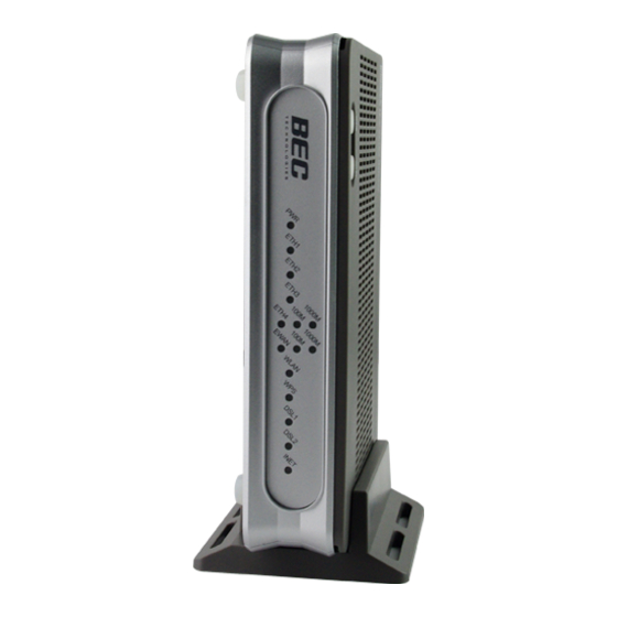
Chapter 2: Product Overview Important note for using this router Package Contents BEC 8920NE The Ultimate Residential Gateway RJ-45 Ethernet Cable Y-Cable for VDSL bonded operation Two wireless detachable antennas Power adaptor... -
Page 12: Device Description
Device Description The Front LEDs Function Lit green: when the device is ready. Power (PWR) No light: when no power is connected. Lit green: when LAN port is connected to an Ethernet device. Ethernet (ETH) 1 - 3 Flashing green: when data is being Transmitted / Received. No light: when no LAN port is not being connected. -
Page 13: The Rear Ports
The Rear Ports Port Function Wireless detachable Connect a wireless detachable antenna to this port. antenna (ANT) Connect the device to an ADSL/VDSL telephone jack or splitter using a RJ-11 telephone cable Connect to a Cable modem, xDSL modem, and Fiber (PON) modem. Connect your computer or an Ethernet device to a LAN port, using the Ethernet (1~4) included Ethernet cable. -
Page 14: Chapter 3: Basic Installation
Chapter 3: Basic Installation You can configure the BEC 8920NE The Ultimate Residential Gateway through the convenient and user-friendly interface of a web browser. Most popular operating systems such as Linux and Windows 98 / NT /2000 / XP / ME / 7 / Vista include a web browser as a standard application. -
Page 15: Network Configuration
Network Configuration Configuring a PC in Windows 7 Start. Click Control Panel. Then click on Network and Internet. When the Network and Sharing Center window pops up, select and click on Change adapter settings on the left window panel. Select Local Area Connection, and right click... - Page 16 Select Internet Protocol Version 4 (TCP/IPv4) then click Properties. In the TCP/IPv4 properties window, select the Obtain address automatically and Obtain Server address automatically radio buttons. Then click OK to exit the setting. Click OK again in the Local Area Connection Properties window to apply the new configuration.
-
Page 17: Configuring A Pc In Windows Vista
Configuring a PC in Windows Vista Start. Click Network. Then click on Network and Sharing Center at the top bar. When the Network and Sharing Center window pops up, select and click on Manage network connections on the left window pane. Select Local Area... - Page 18 Select Internet Protocol Version 4 (TCP/IPv4) then click Properties. In the TCP/IPv4 properties window, select the Obtain an IP address automatically and Obtain DNS Server address automatically radio buttons. Then click OK to exit the setting. Click OK again in the Local Area Connection Properties window to apply...
-
Page 19: Configuring A Pc In Windows Xp
Configuring a PC in Windows XP 1. Go to Start. Click on Control Panel. 2. Then click on Network and Internet. 3. In the Local Area Connection Status window, click Properties. 4. Select Internet Protocol (TCP/IP) and click Properties. 5. Select the Obtain an IP address automatically and the Obtain DNS server address automatically radio buttons. -
Page 20: Configuring A Pc In Windows 2000
Configuring a PC in Windows 2000 1. Go to Start / Settings / Control Panel. In the Control Panel, double-click on Network and Dial-up Connections. 2. Double-click Local Area Connection. 3. In the Local Area Connection Status window click Properties. 4. -
Page 21: Configuring Pc In Windows 98/Me
Configuring PC in Windows 98/Me 1. Go to Start / Settings / Control Panel. In the Control Panel, double-click on Network and choose the Configuration tab. 2. Select TCP/IP ->NE2000 Compatible, or the name of your Network Interface Card (NIC) in your PC. 3. -
Page 22: Configuring Pc In Windows Nt4.0
Configuring PC in Windows NT4.0 1. Go to Start / Settings / Control Panel. In the Control Panel, double-click on Network and choose the Protocols tab. 2. Select TCP/IP Protocol and click Properties. 3. Select the Obtain an IP address from a DHCP server radio button and click OK. -
Page 23: Factory Default Settings
Factory Default Settings Before configuring the router, you need to know the following default settings. Web Interface: (Username and Password) Username: admin Password: admin The default username and password are “admin” and “admin” respectively. If you ever forget the username/password to login to the router, you may press the RESET button up to 6 seconds then release it to restore the factory default settings. -
Page 24: Information From Your Isp
Information from your ISP Before configuring this device, you have to check with your ISP (Internet Service Provider) what kind of services are provided, such as PPPoE, Obtain an IP Address Automatically, Fixed IP address. Gather the information as illustrated in the following table and keep it for reference. VPI/VCI, VC / LLC-based multiplexing,... -
Page 25: Chapter 4: Configuration
The default username and password are “admin” and “admin” respectively for the Administrator account type. Congratulations! You have successfully logged on to your BEC 8920NE The Ultimate Residential Gateway! Once you have logged on to your router via your web browser, you can begin to set it up according to... - Page 26 setup pages, which includes: Status Summary Statistics LAN , WAN Service, xTM, xDSL Bandwidth Usage LAN, WAN Service Route DHCP Log System Log, Security Log Quick Start Configuration LAN Ethernet, IPv6 Autoconfig, Interface Grouping Wireless Basic, Security, MAC Filter, Wireless Bridge, Advanced, Station Info, Schedule Control WAN ...
-
Page 27: Status
Status This Section gives users an easy access to the information about the working router and access to view the current status of the router. Here Summary, WAN, Statistics, Bandwidth Usage, Route, ARP, DHCP, subsections are included. Summary The basic information about the device is provided here (the following is a configured screenshots to let users understand clearly). - Page 28 connects to ISP, it will display the Global Address, like above figure. MAC Address: Displays the MAC address. DSL PHY and Driver Version: Display DSL PHY and Driver version. Wireless Driver Version: Displays wireless driver version. Line Rate – Upstream (Kbps): Displays Upstream line Rate in Kbps. Line Rate –...
-
Page 29: Wan
The WAN Info screen displays the configured PVC(s) and the status. Interface: The WAN connection interface. Description: The description of this connection. Type: The protocol used by this connection. Status: To disconnect or connect the link. Connection Time: The WAN connection time since WAN is up. IPv4 Address: The WAN IPv4 Address the device obtained. -
Page 30: Statistics
Statistics These are the items within the Statistics section: LAN, Service, and xDSL. This screen shows interface statistics of Ethernet LAN interfaces. Interface: List each LAN interface. P1-P4 indicates the four LAN interfaces. Bytes: Display the Received and Transmitted traffic statistics in Bytes. Packets: Display the Received and Transmitted traffic statistics in Packets. -
Page 31: Xtm
The Statistics-xTM screen displays all the xTM statistics Port Number: Shows number of the port for xTM. In Octets: Number of received octets over the interface. Out Octets: Number of transmitted octets over the interface. In Packets: Number of received packets over the interface. Out Packets: Number of transmitted packets over the interface. -
Page 32: Xdsl
xDSL The Statistics-xDSL screen displays all the xDSL network statistics. Mode: Modulation protocol, including G.dmt, G.lite, T1.413, ADSL2, AnnexL, ADSL2+ and AnnexM. Traffic Type: transfer mode, here supports ATM and PTM. Status: Show the status of DSL link. Link Power State: Show link output power state. Line Coding (Trellis): Trellis on/off. - Page 33 INP (DMT symbol): show the DMT symbol. Super Frames: the total number of super frames. Super Frame Errors: the total number of super frame errors. RS Words: Total number of Reed-Solomon code errors. RS Correctable Errors: Total number of RS with correctable errors. RS Uncorrectable Errors: Total number of RS words with uncorrectable errors.
-
Page 34: Bandwidth Usage
Reset: Click this button to reset the statistics. Bandwidth Usage Bandwidth Usage provides users direct view of bandwidth usage with simple diagram. Bandwidth usage shows the use of the bandwidth from two angles: Transmitted and Received, giving users a clear idea of the usage. Note: P4 can be configured as EWAN, and when the device is in EWAN profile, there is no P4/EWAN interface as P4 is working as a WAN port. -
Page 35: Wan Service
When you press View WAN Traffic concurrently button, the WAN Bandwidth Usage pops up so that users can view the WAN traffic concurrently. WAN Service Press View WAN Transmitted button to change the diagram to the statistics from a Received Bytes of view. -
Page 36: Route Table
Press View LAN Traffic concurrently button to directly switch to the LAN Bandwidth Usage page to view the LAN traffic concurrently. Route Table The Rout Table provides users with a database in the router that contains current network topology such as current paths for transmitted packets. -
Page 37: Arp Table
ARP Table This section displays the router’s ARP (Address Resolution Protocol) Table, which shows the mapping of Internet (IP) addresses to Ethernet (MAC) addresses. This is useful as a quick way of determining the MAC address of the network interface of your PCs to use with the router’s Security – MAC Filtering function. - Page 38 Expires in: Show the remaining time after registration. Note: The devices are free to access each other through device name on condition that they all obtain their IPs from the DHCP. If the device IP is obtained from the DHCP, other devices can access the device through the device name.
-
Page 39: Log
System Log Display system logs accumulated up to the present time. You can trace historical information with this function. And the log policy can be configured in Configure Log section. Refresh: Click to update the system log. Clear: Click to clear the current log from the screen. -
Page 40: Security Log
Security Log Security log displays the message logged about security, like filter messages and some firewall message. You can turn to IP Filtering Outgoing, IP Filtering Incoming, URL Filter to determine if you want to log this information. Also you can turn to Configure Log section below to determine the level to log the message. -
Page 41: Quick Start
Quick Start Quick Start This part allows you to quickly configure and connect your router to internet. DSL mode 1. Select DSL, press Continue to go on to next step. 2. Enter the username, password from your ISP, for IP and DNS settings; also refer to your ISP. Here IPv6 service is enabled by default. - Page 42 4. WAN port configuration is successful. 5. After the configuration is successful, click Next to Wireless button and you may proceed to configure the Wireless settings, SSID and encryption Key (1. Leave it empty to disable the wireless security; 2. Fill in the Key, and the encryption mode will be WPA2-PSK/AES). 6.
- Page 43 Ethernet mode 1. Select Ethernet, press Continue to go on to next step. 2. Enter the username, password from your ISP, for IP and DNS settings; also refer to your ISP. Here IPv6 service is enabled by default. 3. Wait while the device is configured. 4.
- Page 44 6. Success.
-
Page 45: Configuration
Configuration When you click this item, the column will expand to display the sub-items that will allow you to further configure your router. Wireless System IP Tunnel Security Quality of Service The function of each configuration sub-item is described in the following sections. -
Page 46: Lan - Local Area Network
LAN - Local Area Network A Local Area Network (LAN) is a shared communication system network where many computers are connected. This type of network is area defined and is usually limited to a confined region within a building. This Section contains the followoing features: Ethernet, IPv6 Autoconfig Interface... - Page 47 CPE, please turn to IP Filtering Incoming to add the allowing rules. Note that all incoming packets by default will be dropped if the LAN side firewall is enabled and user cannot manage this CPE from the specified LAN group. DHCP Server You can disable or enable the DHCP (Dynamic Host Configuration Protocol) server or enable the router’s DHCP relay functions.
- Page 48 Enter the MAC Address, IP Address, and then click Apply to confirm your settings. But the IP assigned should be outside the range of 192.168.1.100-192.168.1.199. IP Alias This function allows the creation of multiple virtual IP interfaces on this router. It helps to connect two or more local networks to the ISP or remote node.
-
Page 49: Ipv6 Autoconfig
IPv6 Autoconfig The IPv6 address composes of two parts, the prefix and the interface ID. There are two ways to dynamically configure IPv6 address on hosts. One is “stateful” configuration, for example using DHCPv6 (which resembles its counterpart DHCP in IPv4.) In the stateful auto-configuration model, hosts obtain interface addresses and/or configuration information and parameters from a DHCPv6 server. - Page 50 routers, but they can obtain such information like DNS from DHCPv6 Server. Stateful: if selected, the PCs in LAN will be configured like in IPv4 mode, thus obtain addresses and DNS information from DHCPv6 server. Start interface ID: Enter the start interface ID. The IPv6 address composed of two parts, thus, the prefix and the interface ID.
- Page 51 Stateless and Stateful IPv6 address Configuration Stateless: Two methods can be carried. With DHCPv6 disabled, but Issue Router Advertisement Enabled With this method, the PCs in LAN are configured through RA mode, thus, the PCs in LAN are configured through RA mode, to obtain the prefix message and generate an address using a combination of locally available information (MAC address) and information (prefix) advertised by routers.
- Page 52 Stateful: two methods can be adopted. With only DHCPv6 enabled With this method, the PCs’ addresses are configured the same as in IPv4, that is addresses are assigned by DHCPv6 server. With both DHCPv6 and Issue Router Advertisement Enabled With this method, the PCs’...
-
Page 53: Interface Grouping
Interface Grouping Interface grouping is a function to group interfaces, known as VLAN. A Virtual LAN, commonly known as a VLAN, is a group of hosts with the common set of requirements that communicate as if they were attached to the same broadcast domain, regardless of the physical location. A VLAN has the same attributes as a physical LAN, but it allows for end stations to be grouped together even if they are not located on the same network... - Page 54 Click Add to add groups. Group Name: Type a group name. Grouped WAN Interfaces: Select from the box the WAN interface you want to applied in the group. Grouped LAN Interfaces: Select the LAN interfaces you want to group as a single group from Available LAN Interfaces.
- Page 55 In group "test", P2 and PPP0.1 are grouped in one group, they have their only network , see LAN. If you want to remove the group, check the box as the following and press Remove. Note: If you like to automatically add LAN clients to a WAN Interface in the new group add the DHCP vendor ID string.
-
Page 56: Wireless
Wireless This section provides you ways to configure wireless access. The BEC 8920NE utilizes two radio bands-2.4GHz to run wireless connection for users. This Section contains the followoing features: Basic, Security, Filter, Wireless Bridge, Advanced, Station Info Schedule Control. Basic It let you determine whether to enable Wireless function and set the basic parameters of an AP and the Virtual APs. - Page 57 Guest/virtual Access Points: A “Virtual Access Point” is a logical entity that exists within a physical Access Point (AP). When a single physical AP supports multiple “Virtual APs”, each Virtual AP appears to stations (STAs) to be an independent physical AP, even though only a single physical AP is present.
-
Page 58: Security
Security Wireless security prevents unauthorized access or damage to computers using wireless network. Note: The WPS feature will also be unavailable when the security setting is not WPA2 or OPEN. So, if you manually set the wireless security setting, you should give notice to it, but you can find prompt indicating configuration. - Page 59 802.1x RADIUS Server IP Address: RADIUS( Remote Authentication Dial In User Service), Enter the IP address of RADIUS authentication server. RADIUS Server Port: Enter the port number of RADIUS authentication server here. RADIUS Key: Enter the password of RADIUS authentication server. WEP Encryption: Select to enable or disable WEP Encryption.
- Page 60 between wireless client and Access Point (AP). This is in seconds. RADIUS Server IP Address: RADIUS( Remote Authentication Dial In User Service), Enter the IP address of RADIUS authentication server. RADIUS Server Port: Enter the port number of RADIUS authentication server here. RADIUS Key: Enter the password of RADIUS authentication server.
- Page 61 WPA2 Preauthentication: When a wireless client wants to handoff to another AP, with preauthentication, it can perform 802.1X authentications to the new AP, and when handoff happens, this mode will help reduce the association time used. Network Re-auth Interval: the interval for network Re-authentication. The unit is second. WPA Group ReKey Internal: The period of renewal time for changing the security key automatically between wireless client and Access Point (AP).
- Page 62 WPS Setup WPS (Wi-Fi Protected Setup) feature is a standard protocol created by Wi-Fi Alliance. WPS is used to exchange the AP setting with Station and configure Ap settings. This feature greatly simplifies the steps needed to create a Wi-Fi network for a residential or an office setting. The commonly known PIN method is supported to configure WPS.
- Page 63 Configure AP as Registrar Add Enrollee with PIN method 1. Select radio button “Enter STA PIN”. 2. Input PIN from Enrollee Station (16837546 in this example), Or else users can alternatively enter the authorized station MAC Help: it is to help users to understand the concept and correct operation.
- Page 64 4. Operate Station to start WPS Adding Enrollee. Launch the wireless client’s WPS utility (eg.Ralink Utility). Set the Config Mode as Enrollee, press the WPS button on the top bar, select the AP (eg. Wlan-ap-2.4g) from the WPS AP List column. Then press the PIN button located on the middle left of the page to run the scan.
- Page 65 You can check the message in the red ellipse with the security parameters you set, here we all use the default.
- Page 66 Configure AP as Enrollee Add Registrar with PIN Method 1. Set AP to “Unconfigured Mode” and Click “Config AP” button. 2. Launch the wireless client’s WPS utility (eg. Ralink Utility). Set the Config Mode as Registrar. Enter the PIN number (13076542 (device) for example) in the PIN Code column then choose the correct AP (eg.
- Page 67 3. The router’s (AP’s) SSID and security setting will now be configured to match the SSID and security setting of the registrar.
- Page 68 4. Do Web Page refresh after ER complete AP Configuration to check the new parameters setting.
-
Page 69: Mac Filter
MAC Filter Select SSID: select the SSID you want this filter applies to. MAC Restrict Mode: Disable: disable the MAC Filter function. Allow: allow the hosts with the following listed MACs to access the wireless network. Deny: deny the hosts with the following listed MACs to access the wireless network. Click Add to add the MACs. -
Page 70: Wireless Bridge
Wireless Bridge WDS (wireless distributed system) is a wireless access point mode that enables wireless link and communication with other access points. It’s easy to install, simply define the peer’s MAC address of the connected AP. WDS takes advantage of cost saving and flexibility with no extra wireless client device required to bridge between two access points and extending an existing wired or wireless infrastructure network to create a larger network. - Page 71 Disable: Does not restrict the gateway communicating with bridges that have their MAC address listed, but it is still open to communicate with all bridges that are in the same network. Click Apply to apply your settings.
-
Page 72: Advanced
Advanced Here users can set some advanced parameters about wireless. Band: select frequency band. Here 2.4GHz. Channel: Allows channel selection of a specific channel (1-7) or Auto mode. Scan Used Channel: Press the button to scan and list all channels being used. Auto Channel Timer (min): The auto channel times length it takes to scan in minutes. - Page 73 RIFS Advertisement: Reduced Inter-frame Spacing (RIFS) is a 802.11n feature that also improves performance by reducing the amount of dead time required between OFDM transmissions. Select Off to disable this function or auto to enable this function. OBSS Co-Existence: coexistence (or not) between 20 MHZ and 40 MHZ overlapping basic service sets (OBSS) in wireless local area networks.
-
Page 74: Station Info
Station Info Here you can view information about the wireless clients. MAC Address: The MAC address of the wireless clients. Associated: List all the stations that are associated with the Access Point. If a station is idle for too long, it is removed from this list Authorized: List those devices with authorized access. -
Page 75: Schedule Control
For example: user wants the SSID “wlan-ap-2.4g” to work on weekdays except for Wednesday, under this circumstance, user can set as shown below. (8920NE offers a optimal way to set two separate timeslots when user needs to activate the SSID during separate intervals. ) -
Page 76: Wan-Wide Area Network
WAN-Wide Area Network A WAN (Wide Area Network) is a computer network that covers a broad geographical area (eg. Internet) that is used to connect LAN and other types of network systems. This Section contains the followoing features: WAN Service, DSL, DSL Bonding, and SNR. - Page 77 PPPoE PPPoE (PPP over Ethernet) provides access control in a manner which is similar to dial-up services using PPP. VCP/VPI: Enter the VCI/VPI combination from you ISP. Encapsulation Mode: Select the encapsulation mode, LLC/SNAP-BRIDGING, or VC/MUX. Description: User-defined description for the connection, commonly for friendly use. 802.1P Priority: The parameter indicates the frame priority level from 0 (lowest) to 7 (highest), which can be used to prioritize different classes of traffic (voice, video, data, etc).
- Page 78 Note: In PPPoE connection, NAT is enabled by default, you can determine whether to enable Fullcone NAT or disable Fullcone NAT and only use NAT, the default NAT type is Port Restricted cone NAT. Of Port-Restricted cone NAT, the restriction includes port numbers. Specifically, an external host can send a packet, with source IP address X and source port P, to the internal host only if the internal host had previously sent a packet to IP address X and port P IPv4 Address: Select whether to set static IPv4 address or obtain automatically.
- Page 79 Click Next to continue to set the default gateway and DNS for IPv4 and IPv6. Default Gateway Select default gateway for you connection (IPv4 and IPv6). Either IPv4 or IPv6, you can choose static setting or select from available interfaces. IPv6 DNS Server’s operation is similar to IPv4 DNS server.
- Page 80 Here you can configure WAN Service, if it is OK, you can access the internet. You can go to Status >WAN or Summary to view the WAN connection information (if your ISP provides IPv6 service, then you will obtain an IPv6 address). (IPv4 or IPv6) PPPoA VCP/VPI: Enter the VCI/VPI combination from you ISP.
- Page 81 Username: Enter the account obtained from the ISP. Password: Enter the password obtained from the ISP. Authentication Method: Default is Auto. Or else your ISP will advise you the appropriate mode. Firewall: Enable to drop all traffic from WAN side. If enabled, all incoming packets by default would be dropped, and please turn to IP Filtering Incoming to add allowing rules.
- Page 82 IP over Ethernet VCP/VPI: Enter the VCI/VPI combination from you ISP. Encapsulation Mode: Select the encapsulation mode, LLC/SNAP-BRIDGING, or VC/MUX. Description: User-defined description for the connection, commonly for friendly use. Authentication Method: Default is Auto. Or else your ISP will advise you the appropriate mode. 802.1P Priority: The parameter indicates the frame priority level from 0 (lowest) to 7 (highest), which can be used to prioritize different classes of traffic (voice, video, data, etc).
- Page 83 WAN Subnet Mask: Enter your submask to the device provided by your ISP. WAN gateway IP Address: Enter your gateway IP address to the device provided by your ISP. IPv6 for this service: Enable to use IPv6 service. Obtain an IPv6 address automatically: check whether to enable or disable this feature. WAN IPv6 Address/Prefix Length: Enter the WAN IPv6 Address/Prefix Length from your ISP.
- Page 84 IPoA VCP/VPI: Enter the VCI/VPI combination from you ISP. Encapsulation Mode: Select the encapsulation mode, LLC/SNAP-BRIDGING, or VC/MUX. Description: User-defined description for the connection, commonly for friendly use. WAN IP: Enter the WAN IP from the ISP. WAN Subnet Mask: Enter the WAN Subnet Mask from the ISP. NAT: The NAT (Network Address Translation) feature allows multiple users to access the Internet through a single IP account by sharing the single IP address.
- Page 85 Bridging VCP/VPI: Enter the VCI/VPI combination from you ISP. Encapsulation Mode: Select the encapsulation mode, LLC/SNAP-BRIDGING, or VC/MUX. Description: User-defined description for the connection, commonly for friendly use. 802.1P Priority: The parameter indicates the frame priority level from 0 (lowest) to 7 (highest), which can be used to prioritize different classes of traffic (voice, video, data, etc).
- Page 86 Ethernet Ethernet WAN connection is well known as directly broadband WAN connection. PPPoE Description: User-defined description for the connection, commonly for friendly use. 802.1P Priority: The parameter indicates the frame priority level from 0 (lowest) to 7 (highest), which can be used to prioritize different classes of traffic (voice, video, data, etc).
- Page 87 Password: Enter the password obtained from the ISP. Service Name: The item is for identification purpose, user can define it yourselfe. Authentication Method: Default is Auto. Or else your ISP will advise you the appropriate mode. Firewall: Enable to drop all traffic from WAN side. If enabled, all incoming packets by default would be dropped, and please turn to IP Filtering Incoming to add allowing rules.
- Page 88 Default Gateway Select a default gateway for you connection (IPv4 and IPv6). Either IPv4 or IPv6, you can choose a static setting or select from available interfaces. IPv6 DNS Server’s operation is similar to IPv4 DNS server. There are two modes to get DNS server address: Auto and static mode.
- Page 89 Here the corresponding WAN Service have been configured, if it is OK, you can access the internet. You can go to Status>WAN or Summary to view the WAN connection information (if your ISP provides IPv6 service, then you will obtain an IPv6 address). (IPv4 or IPv6) IP over Ethernet...
- Page 90 Description: User-defined description for the connection, commonly for friendly use. 802.1P Priority: The parameter indicates the frame priority level from 0 (lowest) to 7 (highest), which can be used to prioritize different classes of traffic (voice, video, data, etc). Enter the priority identification, tagged: 0-1, untagged: -1.
- Page 91 headers) that IP will attempt to send through the interface. MAC Spoofing: This option is required by some service providers specifying some specific MAC allowed to join in network. You must fill in the MAC address specified by your service provider when this information is required.
-
Page 92: Dsl
This screen allows you to set DSL parameters. DSL knowledge is required to configure these settings. Contact your ISP to make sure that these parameters are correct. Modulation: There are 7 modes “G.Dmt”, “G.lite”, “T1.413”, “ADSL2”, “AnnexL”, ”ADSL2+”, “AnnexM” that user can select for this connection. Phone line pair: This is for reserved only. -
Page 93: Dsl Bonding
DSL Bonding This feature allows you to double your VDSL2 data rate . Contact your ISP to see if you can upgrade your Internet service in order to use this feature xDSL Bonding Capability: To enable or disaable the VDSL2 bonding feature. ... -
Page 94: Snr
Signal-to-noise ratio (often abbreviated SNR or S/N) is a measure used in science and engineering that compares the level of a desired signal to the level of background noise. It is defined as the ratio of signal power to the noise power. SNR: Change the value to adjust the DSL link rate, more suitable for an advanced user. -
Page 95: System
System This Section contains the followoing features: Internet Time, Firmware Upgrade, Backup / Update, Access Control, Mail Alert, Confingure Log. Internet Time The router does not have a real time clock on board; instead, it uses the Network Time Protocol (NTP) to get the most current time from an NTP server. -
Page 96: Firmware Upgrade
Firmware Upgrade Software upgrading lets you experience new and integral functions of your router. Restart device with: Factory Default Settings: Restart the device with factory default settings automatically when finishing upgrading. Current Settings: Restart the device with the current settings automatically when finishing upgrading. -
Page 97: Backup / Update
Backup / Update These functions allow you to save and backup your router’s current settings to a file on your PC, or to restore from a previously saved backup. This is useful if you wish to experiment with different settings, knowing that you have a backup handy in the case of any mistakes. -
Page 98: Access Control
Access Control Access Control is used to prevent unauthorized access to the router configuration page. Here you can change the login user password. Three user levels are provided here. Each user level there’s a default provided user. You must access the router with the appropriate username and password. Here the corresponding passwords are allowed to change. -
Page 99: Mail Alert
Mail Alert Mail alert is designed to keep system administrator or other relevant personnel alerted of any unexpected events that might have occurred to the network computers or server for monitoring efficiency. With this alert system, appropriate solutions may be tackled to fix problems that may have arisen so that the server can be properly maintained. -
Page 100: Configure Log
Configure Log Log: Enable or disable this function. Log level: Select your log level. The log level allows you to configure which types of events are logged. There are eight log levels from high to low are displayed below: Emergency = system is unusable ... -
Page 101: Ip Tunnel
IP Tunnel An IP Tunnel is an Internet Protocol (IP) network communication channels between two networks of different protocols. It is used to transport another network protocol by encapsulation of its packets. IP Tunnels are often used to connect two disjoint IP networks that do not have a native routing path to each other, via an underlying routable protocol across an intermediate transport network, like VPN. - Page 102 Mechanism: Here only 6RD. Associated WAN Interface: The applied WAN interface with the set tunnel, thus when there are packets from/to the WAN interface, the tunnel would be used to transport the packets. Associated LAN Interface: Set the linked LAN interface with the tunnel. Method: 6rd operation mechanism: manually configured or automatically configured.
-
Page 103: Ipv4Inipv6
IPv4inIPv6 4in6 refers to tunneling of IPv4 in IPv6. It is an inherent internet interoperation mechanism allowing IPv4 to be used in an IPv6 only network. 4in6 uses tunneling to encapsulate IPv4 traffic over configured IPv6 tunnels. 4in6 tunnels are usually manually configured but they can be automated using protocols such as TSP to allow easy connection to a tunnel broker. -
Page 104: Security
Security This Section contains the followoing features: IP Filtering Outgoing, IP Filtering Incoming, MAC Filtering, Block WAN PING, Time Restriction URL Filter IP Filtering Outgoing IP filtering enables you to configure your router to block specified internal/external users (IP address) from Internet access, or you can disable specific service requests (Port number) to /from Internet. - Page 105 port range is to be blocked from going through the router. Default is set port from port range: 1 – 65535. Time Schedule: Select or set exactly when the rule works. When set to “Always On”, the rule will work all time;...
- Page 106 (Rule inactive)
-
Page 107: Ip Filtering Incoming
IP Filtering Incoming Incoming IP Filtering is set by default to block all incoming traffic, but user can set rules to forward specific incoming traffic. Note: 1. The maximum number of entries: 32. 2. When LAN side firewall or firewall in WAN interface(s) is enabled, user can move here to add allowing rules to pass through the firewall. - Page 108 Or you can select the already set timeslot in “Time Schedule” during which the rule works. And when set to “Disable”, the rule is disabled or inactive and there will be an icon” ” in the list table indicating the rule is inactive. See Time Schedule.
-
Page 109: Mac Filtering
MAC Filtering MAC Filtering is only effective on ATM PVCs configured in Bridged mode. FORWARDED means that all MAC layer frames will be forwarded except those matching with any of the specified rules in the following table. BLOCKED means that all MAC layer frames will be blocked except those matching with any of the specified rules in the following table. -
Page 110: Blocking Wan Ping
Blocking WAN PING This feature is enabled to let your router not respond to any ping command when someone others “Ping” your WAN IP. -
Page 111: Time Restriction
Time Restriction A MAC (Media Access Control) address is the unique network hardware identifier for each PC on your network’s interface (i.e. its Network Interface Card or Ethernet card). Using your router’s MAC Address Filter function, you can configure the network to block specific machines from accessing your LAN during the specified time. - Page 112 Here you can see that the user “child_use” with a MAC of 18:a9:05:04:12:23 is blocked to access the router from 00:00 to 23:59 Monday through Friday. If you needn’t this rule, you can check the box, press Remove, it will be OK.
-
Page 113: Url Filter
URL Filter URL (Uniform Resource Locator – e.g. an address in the form of http://www.abcde.com or http://www.example.com) filter rules allow you to prevent users on your network from accessing particular websites by their URL. There are no pre-defined URL filter rules; you can add filter rules to meet your requirements. - Page 114 Keywords Filtering Note: Maximum number of entries: 32. Click to add the keywords. Enter the Keyword, for example image, and then click Add. You can add other keywords like this. The keywords you add will be listed as above. If you want to reedit the keyword, press the Edit radio button left beside the item, and the word will listed in the Keyword field, edit, and then press Edit/Delete to confirm.
- Page 115 depending on which you selected previously. For specific process, please refer to Keywords Filtering. Exception IP Address In the section, users can set the exception IP respectively for IPv4 and IPv6. Click to add the IP Addresses. Enter the except IP address. Click Add to save your changes. The IP address will be entered into the Exception List, and excluded from the URL filtering rules in effect.
-
Page 116: Qos - Quality Of Service
QoS - Quality of Service Quality of Service QoS helps you to control the data upload traffic of each application from LAN (Ethernet) to WAN (Internet). This feature allows you to control the quality and speed of throughput for each application when the system is running with full upstream load. - Page 117 value. IP Precedence and DSCP Mapping Table Mapping Table Default (000000) Best Effort Expedited Forwarding EF(101110) Assured Forwarding Class1(L) AF11 (001010) Assured Forwarding Class1(M) AF12 (001100) Assured Forwarding Class1(H) AF13 (001110) Assured Forwarding Class1(L) AF21 (010010) Assured Forwarding Class1(M) AF22 (010100) Assured Forwarding Class1(H) AF23 (010110) Assured Forwarding Class1(L)
- Page 118 External IP Address: The IP address on remote / WAN side. External Port: The Port number on the remote / WAN side. Time Schedule: Select or set exactly when the rule works. When set to “Always On”, the rule will work all time;...
- Page 119 Examples: Common usage 1. Give outgoing VoIP traffic more priority. The default queue priority is normal, so if you have VoIP users in your local network, you can set a higher priority to the outgoing VoIP traffic. 2. Give regular web http access a limited rate...
- Page 120 3. If you are actively engaged in P2P and are afraid of slowing down internet access for other users within your network, you can then use QoS to set a rule that has low priority. In this way, P2P application will not congest the data transmission with other applications. Other applications, like FTP, Mail access, users can use QoS to control based on need.
-
Page 121: Qos Port Shaping
QoS Port Shaping QoS port shaping supports traffic shaping of Ethernet interfaces. It forcefully maximizes the throughput of the Ethernet interface. When “Shaping Rate” is set to “-1”, no shaping will be in place and the “Burst Size” is to be ignored. Interface: P1-P4. -
Page 122: Nat
NAT (Network Address Translation) feature translates a private IP to a public IP, allowing multiple users to access the Internet through a single IP account, sharing the single IP address. It is a natural firewall for the private network. This Section contains the followoing features: Exceptional Rule, Virtual Server, DMZ Host, One-to-One NAT, Port Triggering ALG. -
Page 123: Virtual Server
Virtual Server In TCP/IP and UDP networks a port is a 16-bit number used to identify which application program (usually a server) incoming connections should be delivered to. Some ports have numbers that are pre-assigned to them by the IANA (the Internet Assigned Numbers Authority), and these are referred to as “well-known ports”. - Page 124 Interface: select from the drop-down menu the interface you want the virtual server(s) to apply. Server Name: select the server name from the drop-down menu. Custom Service: It is a kind of service to let users customize the service they want. Enter the user-defined service name here.
- Page 125 2. Press Apply to conform, and the items will be list in the Virtual Servers Setup table. Means the rule is inactive) Remove If you don’t need a specified Server, you can remove it. Check the check box beside the item you want...
- Page 126 to remove, then press Remove, it will be OK.
-
Page 127: Dmz Host
DMZ Host The DMZ Host is a local computer exposed to the Internet. When setting a particular internal IP address as the DMZ Host, all incoming packets will be checked by Firewall and NAT algorithms before being passed to the DMZ host, when a packet received does not use a port number used by any other Virtual Server entries. -
Page 128: One-To-One Nat
One-to-One NAT One-to-One NAT maps a specific private/local address to a global/public IP address. If user has multiple global/public IP addresses from your ISP, you are free to use one-to-one NAT to assign some specific public IP for an internal IP like a public web server mapped with a global/public IP for outside access. -
Page 129: Port Triggering
Port Triggering Port triggering is a way to automate port forwarding with outbound traffic on predetermined ports (‘triggering ports’), incoming ports are dynamically forwarded to the initiating host, while the outbound ports are in use. Port triggering triggers can open an incoming port when a client on the local network makes an outgoing connection on a predetermined port or a range of ports. - Page 130 Open port Start: Enter a port number as the open port staring number. End: Enter a port number as the open port ending number. Any port in the range delimited by the ‘Start’ and ‘End’ would be the preset forwarding port or open port.
- Page 131 Remove If you don’t need a specified Server, you can remove it. Check the check box beside the item you want to remove, and then press Remove.
-
Page 132: Alg
The ALG Controls enable or disable protocols over application layer. -
Page 133: Advanced Setup
Advanced Setup There are sub-items within the System section: Routing, DNS, Static ARP, UPnP, Multicast, Management, and Diagnostics. -
Page 134: Routing
Routing This Section contains the followoing features: Default Gateway, Static Route, Policy Routing RIP. Default Gateway WAN port: Select the port this gateway applies to. To set Default Gateway and Available Routed WAN Interface. This interfaces are the ones you have set in WAN section, here select the one you want to be the default gateway by moving the interface via . -
Page 135: Static Route
Static Route With static route feature, you can control the routing of all the traffic across your network. With each routing rule created, you can specifically assign the destination where the traffic will be routed. Above is the static route listing table, click Add to create static routing. IP Version: Select the IP version, IPv4 or IPv6. -
Page 136: Policy Routing
Policy Routing Here users can set a route for the host (source IP) in a LAN interface to access outside through a specified Default Gateway or a WAN interface. The following is the policy Routing listing table. Click Add to create a policy route. Policy Name: User-defined name. -
Page 137: Rip
RIP, Router Information Protocol, is a simple Interior Gateway Protocol (IGP). RIP has two versions, RIP-1 and RIP-2. Interface: the interface the rule applies to. Version: select the RIP version, there are two versions, RIP-1 and RIP-2. Operation: RIP has two operation mode. ... -
Page 138: Dns
DNS, Domain Name System, is a distributed database of TCP/IP application. DNS provides translation of Domain name to IP. This Section contains the followoing features: DNS, Dynamic DNS, DNS Proxy Static DNS. IPv6 DNS Server’s operation is similar to IPv4 DNS server. There are two modes to get DNS server address: Auto and Static mode. -
Page 139: Dynamic Dns
Dynamic DNS The Dynamic DNS function allows you to alias a dynamic IP address to a static hostname, allowing users whose ISP does not assign them a static IP address to use a domain name. This is especially useful for hosting servers via your ADSL connection, so that anyone wishing to connect to you may use your domain name, rather than having to use your dynamic IP address, which changes from time to time. - Page 140 User can register different DDNS to different interfaces. Examples: Note first users have to go to the Dynamic DNS registration service provider to register an account. User test register two Dynamic Domain Names in DDNS provider http://www.dyndns.org/ 1. pppoe_0_0_35 with DDNS: www.hometest.com using username/password test/test 2.
-
Page 141: Dns Proxy
DNS Proxy DNS proxy is used to forward request and response message between DNS Client and DNS Server. Hosts in LAN can use router serving as a DNS proxy to connect to the DNS Server in public to correctly resolve Domain name to access the internet. DNS Proxy: Select whether to enable or disable DNS Proxy function, default is enabled. -
Page 142: Upnp
UPnP UPnP offers peer-to-peer network connectivity for PCs and other network devices, along with control and data transfer between devices. UPnP offers many advantages for users running NAT routers through UPnP NAT Traversal, and on supported systems makes tasks such as port forwarding much easier by letting the application control the required settings, removing the need for the user to control advanced configuration of their device. - Page 143 Components selection box. Step 4: Click OK to go back to the Add/Remove Programs Properties window. Click Next. Step 5: Restart the computer when prompted. Follow the steps below to install the UPnP in Windows XP. Step 1: Click Start and Control Panel. Step 2: Double-click Network Connections.
- Page 144 Step 5: In the Networking Services window, select the Universal Plug and Play check box. Step 6: Click OK to go back to the Windows Optional Networking Component Wizard window and click Next. Auto-discover Your UPnP-enabled Network Device Step 1: Click start and Control Panel. Double-click Network Connections. An icon displays under Internet Gateway.
- Page 145 Step 3: In the Internet Connection Properties window, click Settings to see the port mappings that were automatically created. Step 4: You may edit or delete the port mappings or click Add to manually add port mappings.
- Page 146 Step 5: Select Show icon in notification area when connected option and click OK. An icon displays in the system tray Step 6: Double-click on the icon to display your current Internet connection status.
- Page 147 Step 3: Select My Network Places under Other Places. Step 4: An icon describing each UPnP-enabled device shows under Local Network. Step 5: Right-click on the icon of your BiPAC 8920NE and select Invoke. The web configuration login screen displays.
-
Page 148: Multicast
Multicast Multicast is one of the three network transmission modes, Unicast, Multicast, Broadcast. It is a transmission mode that supports point-to-multipoint connections between the sender and the recipient. IGMP protocol is used to establish and maintain the relationship between IP host and the host directly connected multicast router. - Page 149 Query Response Interval: Enter the response interval time (sec). Last Member Query Interval: Enter the interval time (sec) the multicast router query the specified group after it has received leave message. Robustness Value: Enter the router robustness parameter, 2-7, the greater the robustness value, the more robust the Querier is.
-
Page 150: Management
Management This Section contains the followoing features: SNMP Agent, TR-069 Client, Remote Access Time Schedule. SNMP Agent SNMP, Simple Network Management Protocol, is the most popular one in network. It consists of SNMP Manager,SNMP Agent and MIB. Every network device supporting SNMP will have a SNMP Agent which is a management software running in the device. -
Page 151: Tr- 069 Client
TR- 069 Client TR-069 (short for Technical Report 069) is a DSL Forum (which was later renamed as Broadband Forum) technical specification entitled CPE WAN Management Protocol (CWMP). It defines an application layer protocol for remote management of end-user devices. As a bidirectional SOAP/HTTP based protocol it can provides the communication between customer premises equipment (CPE) and Auto Configuration Server (ACS). -
Page 152: Remote Access
Remote Access It is to allow remote access to the router to view or configure. Remote Access: Select “Enable” to allow management access from remote side (mostly from internet). If disabled, no remote access is allowed for any IPs even if you set allowed access IP address. -
Page 153: Time Schedule
Time Schedule The Time Schedule supports up to 32 timeslots which helps you to manage your Internet connection. In each time profile, you may schedule specific day(s) i.e. Monday through Sunday to restrict or allowing the usage of the Internet by users or applications. This Time Schedule correlates closely with router’s time, since router does not have a real time clock on board;... -
Page 154: Diagnostics
Diagnostic Tools, Push Service, Diagnostics Fault Magangement. Diagnostics Tools BEC 8920NE offers diagnostics tools including “Ping” and “Trace route test” tools to check for problems associated with network connections. Ping Test: to verify the connectivity between source and destination. Destination Host: Enter the destination host (IP, domain name) to be checked for connectivity. - Page 155 Example: Ping www.google.com...
- Page 156 Example: “trace” www.google.com...
-
Page 157: Push Service
Push Service With push service, the system can send email messages with consumption data and system information. Recipient’s E-mail: Enter the destination mail address. The email is used to receive system log , system configuration,security log sent by the device when the Push Now button is pressed (information sent only when pressing the button ), but the mail address is not remembered. -
Page 158: Diagnostics
Diagnostics Check the connections, including Ethernet connection, Internet Connection and wireless connection. Click Help link that can lead you to the interpretation of the results and the possible, simply troubleshooting. -
Page 159: Fault Management
Fault Management IEEE 802.1ag Connectivity Fault Management (CFM) is a standard defined by IEEE. It defines protocols and practices for OAM (Operations, Administration, and Maintenance) for paths through 802.1 bridges and local area networks (LANs). Fault Management is to uniquely test the VDSL PTM connection;... -
Page 160: Restart
Restart This section lets you restart your router if necessary. Click in the low right corner of each configuration page. If you wish to restart the router using the factory default settings (for example, after a firmware upgrade or if you have saved an incorrect configuration), select Factory Default Settings to reset to factory default settings. -
Page 161: Chapter 5: Troubleshooting
If your router is not functioning properly, please refer to the suggested solutions provided in this chapter. If your problems persist or the suggested solutions do not meet your needs, please kindly contact your service provider or BEC for support. Problems with the router... -
Page 162: Appendix: Product Support & Contact
Appendix: Product Support & Contact If you come across any problems please contact the dealer from where you purchased your product. Contact BEC @ http://www.bectechnologies.net MAC OS is a registered Trademark of Apple Computer, Inc. Windows 7/98, Windows NT, Windows 2000, Windows Me, Windows XP and Windows Vista are registered...
Need help?
Do you have a question about the 8920NE and is the answer not in the manual?
Questions and answers