Advertisement
Quick Links
Amphenol AMPHE-EX Assembly Instructions
.
L-2124
For additional information, consult Amphenol AMPHE-EX Catalog, 12-056
©Amphenol EEC, Des Plaines, IL, USA
Document Contents:
• Familiarization & Assembly
• Contact Preparation and Installation
• Connector Assembly
• Part Number Code Logic
Amphenol EEC
AMPHE-EX
Page 1 of 17
Printed in U.S.A. 10/2022
Revision N
Advertisement

Related Manuals for Amphenol AMPHE-EX L-2124


Summary of Contents for Amphenol AMPHE-EX L-2124
- Page 1 Document Contents: • Familiarization & Assembly • Contact Preparation and Installation • Connector Assembly • Part Number Code Logic For additional information, consult Amphenol AMPHE-EX Catalog, 12-056 ©Amphenol EEC, Des Plaines, IL, USA Printed in U.S.A. 10/2022 Revision N Amphenol EEC AMPHE-EX ...
-
Page 2: Description Of Equipment
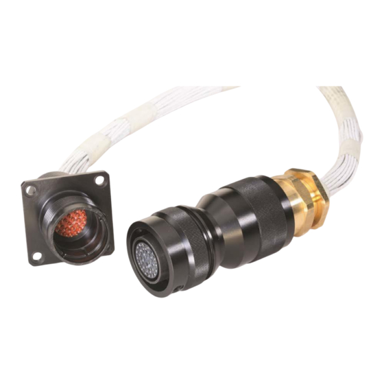
Description of equipment The Amphe-EX Connectors each comprise a metallic bodied plug or receptacle shell, to form in-line cable connections. Externally the main body is fitted with a suitably certified cable gland. Internally the main bodies each contain an insulator insert fitted with solder type contact pins or sockets. - Page 3 Familiarization & Assembly Information Read manufacturer’s assembly instructions before actually starting Be sure that any ground contacts (when applicable) are correctly to assemble connectors. Besides the matter of instruction on correct located. procedures, there are two important reasons for this preliminary step: To identify the various component parts, and to check for any 10.
- Page 4 Components to be incorporated into or used as replacement parts of the equipment shall be fitted by suitably trained personnel, using only components purchased from Amphenol or an Amphenol approved distributor. Any use of non- approved components/suppliers will invalidate the certification for that product.
- Page 5 c. (Optional Base Material) ASTM B455, Alloy C38500, Brass 2) O-ring Seal Material: Silicone w/ Durometer of 70 SHORE A If the equipment is likely to come into contact with aggressive substances, then it is the responsibility of the user to take suitable precautions that prevent it from being adversely affected, thus ensuring that the type of protection provided by the equipment is not compromised.
- Page 6 • The interface between the panel mount receptacles and associated increased safety enclosure to which they may be fitted cannot be defined. Therefore it is the user’s responsibility to ensure that the appropriate ingress protection level of the associated enclosure is maintained at this point. •...
- Page 7 Contact Preparation Instructions Insert stripped wire into contact applying slight Crimp Tools: pressure until wire insulation butts against wire well. Check inspection hole to see that wire strands are M22520 Series is recommended. See Tool Table in visible. If there are strayed wire strands, entire wire catalog, for choice of turret head and selection setting end should be re-twisted.
- Page 8 Slide securing devices forward and tighten using connector pliers. Connector holding tools are recommended while tightening back accessories. Soldering Work Instructions Soldering is the process in which two or more products are joined together by melting and flowing a filler (solder) into the joint, adhering to the standards specified in IPC/WHMA-A-620B.
- Page 9 CAUTION: WHEN INSERTING OR REMOVING CONTACTS, DO NOT SPREAD OR ROTATE TOOL TIPS. Removal: Slip correct sized tool (with plastic tool, use white end) over wire insulation and slide forward on wire until tool tip enters rear grommet and comes to a positive stop on contact shoulder. Grip wire, and simultaneously remove tool, contact and wire.
- Page 10 (TYPICAL) Page 10 of 17...
- Page 11 Panel Mount Receptacle Shell that is held in a table mounted vise. 9) After hand tightening the Ex Gland onto the Cable Adapter, refer to Amphenol’s EX-35/EX-45 Cable Gland Fitting Instructions, for instruction on complete securement of the Cable Gland to the cable adapter, and seal compression around the cable jacket.
- Page 12 Hermetic receptacle version employs HYSOL EE4183-HD3404. This material is a two-component casting system with a 100:9 volumetric mix ratio. These products are available in pre-measured “mix & dispense” packaging. More information is available by contacting the following authorized suppliers: Amphenol EEC 1701 Birchwood Ave. Des Plaines, IL 60018 USA Phone (773) 463-8343...
- Page 13 Bulkhead Adapter Bulkhead adapters should be filled to a minimum of 1/16” below the top of the adapter, as shown. Potting flush with end of adapter is acceptable. Care must be exercised so that the potting compound does not contaminate the bulkhead threads, or spill onto the surfaces of the receptacle flange.
- Page 14 Epoxy Volume Per Bulkhead Adapter Shell Fill Length Adapter Internal Internal Size inside Adapter Diameter Volume Volume* (inches) (inches) (in ^ 3) (ounces) 0.652 0.434 0.24 0.652 0.434 0.24 0.927 0.877 0.49 0.927 0.877 0.49 1.242 1.575 0.87 1.242 1.575 0.87 1.242 1.575...
- Page 15 ATEX or IECEX CERTIFIED CABLE GLAND, IP6X RATED, WITH SEALS TEMP RATED -20°C TO +85°C MIN, (WHERE -40°C≤Ta≤+40°C) -20°C TO +100°C MIN, (WHERE -40°C≤Ta≤+55°C) Figure 2: Panel Mount Configuration: Inline Plug mated to Bulkhead Receptacle. Figure 3: Hermetic Panel Mount Configuration: Inline Plug mated to Hermetic Panel Mount Receptacle Page 15 of 17...
- Page 16 Panel Mount Receptacle Part # Threaded Spigot Size Threaded Spigot Size (Metric adapter ver) (NPT adapter) (6 threads min,) a)02 –(9-d)(e)(f)(g) EXM-( ¾” NPT M25x1.5-6g a)02 –(11-d)(e)(f)(g) EXM-( ¾” NPT M25x1.5-6g a)02 –(13-d)(e)(f)(g) EXM-( 1” NPT M32x1.5-6g a)02 –(15-d)(e)(f)(g) EXM-( 1”...
- Page 17 ATEX & IECEx Product Labeling Information Information below must be attached to connectors via non-removable label. Amphenol EEC Des Plaines, IL 60018 USA Part Number, Revision “Max Volts, Max Amps, Current Rating per pin” Date of Manufacture and Date Code 2813 Plug Connectors, cord mounted - Shell configuration (06) - ATEX/IECEx Certificate Number: SIRA 07ATEX1229X/IECEx SIR 08.0029X...
Need help?
Do you have a question about the AMPHE-EX L-2124 and is the answer not in the manual?
Questions and answers