
Subscribe to Our Youtube Channel
Related Manuals for Hope Industrial Systems HIS-RL17-H Series


Summary of Contents for Hope Industrial Systems HIS-RL17-H Series
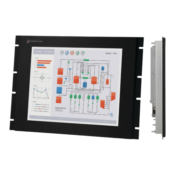
- Page 1 17" RACK MOUNT INDUSTRIAL MONITOR REVISION H USER MANUAL Model No. HIS-RL17- _ _ _ H...
-
Page 2: Table Of Contents
Table of Contents Safety and Regulatory Information ��������������������������������������������������������������������������������3 FCC Notice ����������������������������������������������������������������������������������������������������������������������������� 3 Hazardous Locations �������������������������������������������������������������������������������������������������������������� 4 Waste Electrical and Electronic Equipment Directive (WEEE) ����������������������������������������������� 4 Mechanical Drawings ������������������������������������������������������������������������������������������������������5 Front View ������������������������������������������������������������������������������������������������������������������������������� 5 Bottom View ���������������������������������������������������������������������������������������������������������������������������� 5 Rear View ������������������������������������������������������������������������������������������������������������������������������� 6 Side View ��������������������������������������������������������������������������������������������������������������������������������... -
Page 3: Safety And Regulatory Information
Safety and Regulatory Information Safety and Regulatory Information WARNING! To prevent fire or shock hazard, do not expose the unit to rain or moisture. Dangerously high voltages are present inside the unit� Do not disassemble the unit. Refer servicing to qualified personnel only. Operator could be exposed to dangerously high voltage if AC power is not connected properly�... -
Page 4: Hazardous Locations
Users should contact their supplier and check the terms and conditions of the purchase contract� When purchased directly from Hope Industrial Systems, you may contact technical support for disposal arrangements. -
Page 5: Mechanical Drawings
Mechanical Drawings Mechanical Drawings Front View 482.6 mm (19.00") 6.4 mm (0.25") 272.8 mm (10.74") 354.8 mm (13.97") 317.1 mm (12.48") 340.4 mm (13.40") 215.5 mm (8.48") 139.3 mm (5.48") 37.7 mm 458.8 mm (1.48") (18.06") Bottom View 348.0 mm (13.7") 44.2 mm (1.74") 3.2 mm (0.125") -
Page 6: Rear View
Mechanical Drawings Rear View 75 and 100 mm VESA MOUNTING PATTERN (M4 SCREWS PROVIDED, 16 mm MAXIMUM DEPTH OF SCREW) Side View 52.1 mm (2.05") 291.1 mm (11.46") 7.1 mm (0.28") RL17H User Manual, 99166B, November 2022... -
Page 7: Installation Instructions
Installation Instructions Installation Instructions Step 1: Prepare for Installation IMPORTANT! Perform the following steps BEFORE installation of the monitor into the rack. 1� Ensure that sufficient power is available. 2� Ensure that sufficient space is available to allow for proper air flow into and out of the unit�... -
Page 8: Step 2: Bench-Test Configuration
Installation Instructions Step 2: Bench-test Configuration Make sure everything works before installing into the production environment. TIP! If using a KVM extender, please refer to the installation instructions included with the KVM extender module. It is particularly important to bench-test the full configuration prior to final installation. - Page 9 Installation Instructions TIP! To avoid incompatibility issues, use only certified video adapters available from Hope Industrial Systems. Many 3rd-party signal adapters are known to cause signaling issues� Power Connection The HIS-RL17 is available with either AC or DC power input�...
-
Page 10: Connect And Set Up Touch Screen
To use the touch screen Serial (RS-232) interface, a serial cable may be ordered separately� Instructions below apply to Windows systems� Contact Hope Industrial Systems if you require a CD-ROM with documentation and touch screen drivers. For a full list of downloadable drivers, please check the following address: https://www�HopeIndustrial�com/support/drivers/... - Page 11 Installation Instructions Installing the Driver: Serial (RS-232) Connections Serial Connections must be made before installing the driver. 1� Connect one end of the Serial cable to the Serial input port on the rear of the monitor� Connect the other end to the Serial port on the host computer. Tighten the screw locks on the cable connectors to ensure adequate strain relief�...
-
Page 12: Step 3: Install Into Rack
Hope Industrial Systems' Rack Mount monitors conform to the Electronic Industries Association standard EIA-310-D. Our monitors will fit in type A, B, and C racks with a width of 482.6 mm (19") (preferred EIA rack width)�... -
Page 13: Video Settings
Video Settings Video Settings Setting the Timing Mode Setting the timing mode of your computer graphics adapter (or other video source) is important for maximizing the quality of the screen image and for minimizing eye strain. The timing mode consists of the resolution (e.g. 1280 x 1024) and refresh rate (or vertical frequency; e.g. 60 Hz). After setting the timing mode, use the On-Screen Display (OSD) controls to adjust the screen image. -
Page 14: Control Panel Buttons
Video Settings Control Panel Buttons Use the control panel buttons located on the back of the monitor to display and adjust various settings on the On-Screen Display (OSD) menu. CONTROL PANEL BUTTONS 1� To open the OSD menu, press the Menu button. NOTE: All OSD menus and adjustments screens disappear automatically after 60 seconds. - Page 15 Video Settings Button Control Functions Menu • Opens the OSD menu� • Exits the submenu� • Exits the OSD menu� Select / When the OSD menu IS NOT displayed: Navigate Down • Shortcut to Auto setup function� When the OSD menu IS displayed: •...
-
Page 16: On-Screen Display (Osd) Menus
Video Settings On-Screen Display (OSD) Menus To open the OSD menu, press the Menu button once. Main Menu Description Picture Includes the Contrast, Brightness, Sharpness, and Color functions� VGA Settings Includes the Timing, Auto setup, H total, V position, H position, and Phase functions�... - Page 17 Video Settings Color Menu The Color submenu in the Picture menu includes the Auto color, Theme mode, Gamma, Color balance, and User color functions� Color Menu Description Auto color Auto color is an auto adjust routine to compensate, for example, analog signal level drops on long VGA cables.
-
Page 18: Vga Settings Menu
Video Settings Color Menu Description Color balance Provides several color adjustment modes, including preset color temperatures and a User color mode that allows individual adjustment of Red, Green, and Blue. The factory default setting for this product is Normal� • User color allows individual adjustment of Red, Green, and Blue�... -
Page 19: Setup Menu
Video Settings VGA Settings Menu Description H total Allows the user to fine tune the horizontal timing by increasing or decreasing the total horizontal pixels. H total affects how the image is stretched horizontally. V position (Vertical Moves the screen image up and down. Position) H position (Horizontal Moves the screen image left and right. - Page 20 Video Settings Setup Menu Description The OSD submenu provides several adjustments for the OSD menu settings. • Time out sets the length of time (in seconds) the OSD screen is displayed. For example, with a "60" setting, if a control is not pushed within 60 seconds, the display screen disappears�...
- Page 21 Video Settings Setup Menu Description Source scan Allows the user to turn source scan "On" or "Off." When Source scan is enabled and there is no active video signal present, the display will cycle through video connections until a video source is detected�...
-
Page 22: Cleaning Instructions
Cleaning Instructions Cleaning Instructions CAUTION! DO NOT USE ABRASIVE MATERIALS, SUCH AS PAPER TOWELS OR DIRTY SHOP RAGS, ON THE DISPLAY AS IT WILL SCRATCH THE PROTECTIVE COATING. ALWAYS USE A SOFT CLOTH, PREFERABLY MADE OF COTTON. IMPORTANT! Always spray the cleaner on the cloth or towel first and then clean the monitor screen. -
Page 23: Troubleshooting
If the problem still exists, try bypassing the KVM extender. If this fixes the problem and allows the monitor to work properly, then the KVM extender is the source of the problem� Please refer to the troubleshooting section of the KVM extender manual or contact Hope Industrial Systems for additional assistance. Symptom Causes... - Page 24 Troubleshooting Symptom Causes Solutions "Scanning Ports / No Video cable is not plugged Check the video cable connection at Signal" message box in correctly� the monitor, PC, and/or KVM extender. and no image on the PC is not powered on� Ensure PC is powered on�...
-
Page 25: Touch Screen Troubleshooting
Troubleshooting Touch Screen Troubleshooting Applies to touch screen monitors only� To be sure that you have the most current driver, please check the following address: https://www�HopeIndustrial�com/support/drivers/ Symptom Causes Solutions No response Touch screen cable is not Make sure either the USB or Serial touch when touching plugged in correctly. -
Page 26: Specifications
Specifications Specifications Display Type Thin-film transistor (TFT) Active Matrix Liquid Crystal Size 17" diagonal Image Size (W x H) 338 mm x 270 mm (13�3" x 10�6") Native Resolution SXGA (1280 x 1024, 5:4 aspect ratio) Minimum Resolution VGA (640 x 480) Pixel Pitch 0�264 mm x 0�264 mm Number of Colors... -
Page 27: Video
Input Connectors • HD-15, DVI-I • Optional adapters are available for other connection types (contact Hope Industrial Systems for details) Input Signal Formats • RGB Analog video, 0.7/1.0 Vp-p, 75 Ohms Compatible sync modes: Separate H/V sync, Composite sync, Sync on Green •... -
Page 28: Physical
Specifications Physical Enclosure Type Rack mount Panel Rating Built to IP20 standards; NEMA/UL Type 1 Bezel Finish Black Powder-Coated Carbon Steel, matte finish Depth Behind Bezel 44�2 mm (1�74") Front Bezel Outside 482�6 mm x 354�8 mm x 3�2 mm (19�0" x 13�97" x 0�125") Dimensions (W x H x D) Net Weight 16 lbs�... -
Page 29: Compliances And Certifications
Specifications Compliances and Certifications Electrical • UL/EN/IEC62368-1, UL Recognized Component (File No. E212889) • UL 508A Listed (File No� E318630) • FCC Class A • CAN ICES-3A/NMB-3A • • UKCA • NOM (Registration No. NOM-019-SCFI-1998) NOTE: DC power must use shielded DC input cable Environmental WEEE (Registration No. -
Page 30: Warranty Statement
The warranty remains in force for a five year period beginning on the date we invoice you. If Hope Industrial Systems repairs or replaces a product under warranty, its warranty term is not extended, but the repair itself is warranted for 90 days�... - Page 31 (This page intentionally left blank.) RL17H User Manual, 99166B, November 2022...
- Page 32 Phone: +39 80 0740414 Phone: +33 8 05 08 05 19 Phone: +49 800 001 0486 HopeIndustrial.it HopeIndustrial.fr HopeIndustrial.de Spain Mexico Phone: +34 91 1438229 Phone: +52 800 9531935 HopeIndustrial.es HopeIndustrial.mx RL17H User Manual, 99166B, November 2022 © 2022 Hope Industrial Systems, Inc.
Need help?
Do you have a question about the HIS-RL17-H Series and is the answer not in the manual?
Questions and answers